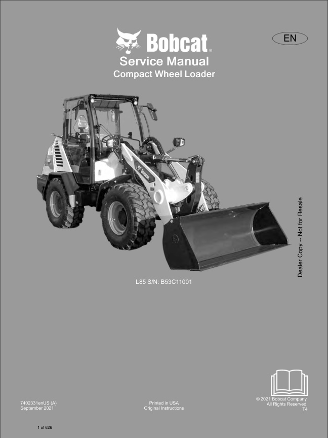
Bobcat L85 Loader B53C11001 7402331 (Preview)
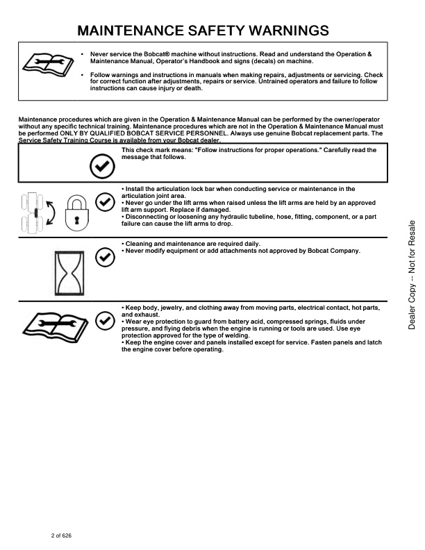
MAINTENANCE SAFETY WARNINGS
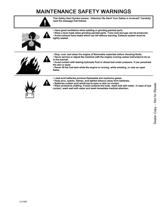
MAINTENANCE SAFETY WARNINGS
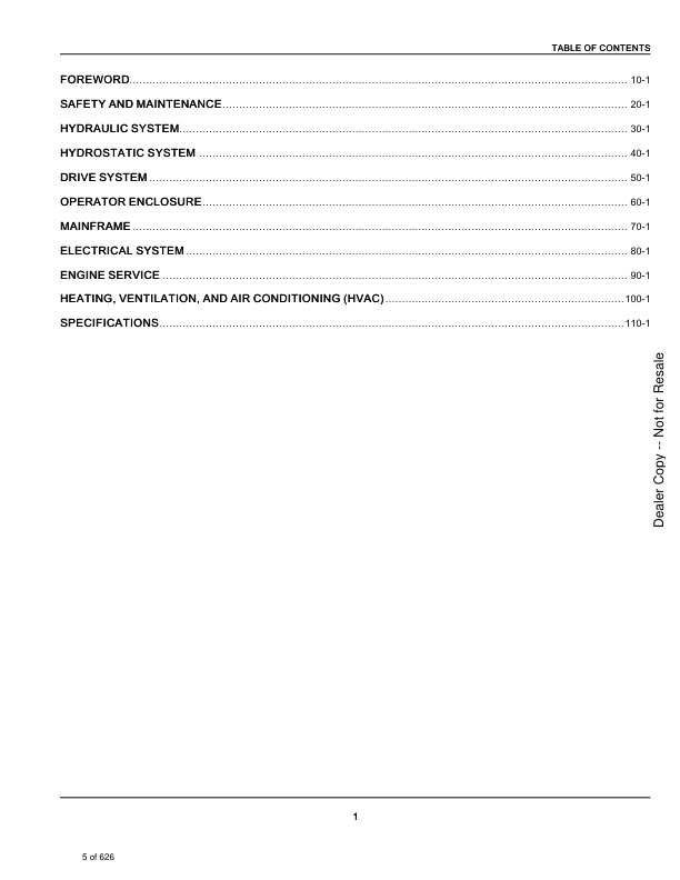
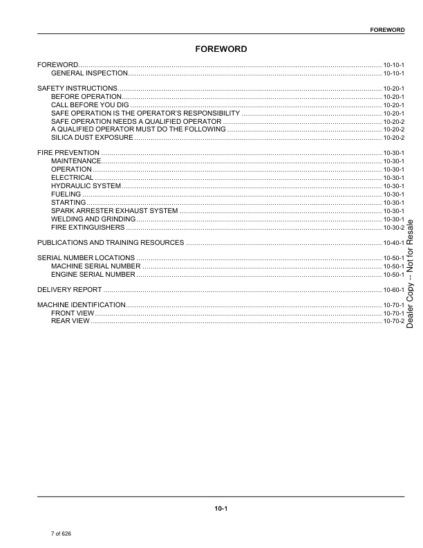
CONTENTS
FOREWORD
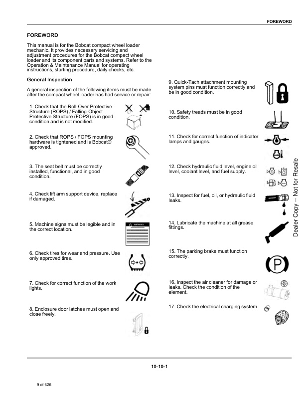
FOREWORD
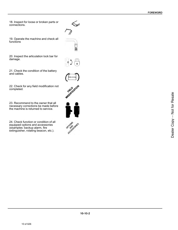
General Inspection
SAFETY INSTRUCTIONS
Before Operation
Call Before You Dig
Safe Operation Is The Operator’s Responsibility
Safe Operation Needs A Qualified Operator
A Qualified Operator Must Do The Following
Silica Dust Exposure
FIRE PREVENTION
Maintenance
Operation
Electrical
Hydraulic System
Fueling
Starting
Spark Arrester Exhaust System
Welding And Grinding
Fire Extinguishers
PUBLICATIONS AND TRAINING RESOURCES
SERIAL NUMBER LOCATIONS
Machine Serial Number
Engine Serial Number
DELIVERY REPORT
MACHINE IDENTIFICATION
Front View
Rear View
SAFETY AND MAINTENANCE
SERVICE SCHEDULE
Maintenance Intervals
REMOTE START TOOL (SERVICE TOOL) KIT – 7217666
Remote Start Tool Description
Remote Start Tool – 7022042
Service Tool Harness – 6689747
Computer Service Tool Harness – 6689746
OPERATOR ENCLOSURE
Operator Enclosure Description
Operator Cab
Door Operation
Wiper Operation
Filling Washer Fluid Tank
Operating The Cab Light
Sun Visor
Operating The Beacon / Strobe
Fire Extinguisher
EMERGENCY EXITS
Performing An Emergency Exit
OPERATOR INTERLOCK CONTROL SYSTEM
Operator Interlock Control System Description
Inspecting The Seat Switch
Inspecting The Lift Arm Bypass Control
STOPPING THE ENGINE AND LEAVING THE MACHINE
Stopping The Engine And Leaving The Machine Procedure
TRANSPORTING THE MACHINE
Loading And Unloading
Fastening
TOWING THE MACHINE
Towing Procedure
Disengaging The Parking Brake
Disengaging The Hydrostatic Pump
Engaging The Hydrostatic Pump
Engaging The Parking Brake
LIFTING THE MACHINE
Lifting Procedure
LIFTING AND BLOCKING THE MACHINE
Lifting And Blocking Procedure
SEAT BELT
Inspecting And Maintaining The Seat Belt
ARTICULATION LOCK BAR
Installing The Articulation Lock Bar
LIFT ARM SUPPORT
Lift Arm Support Description
Installing The Lift Arm Support
Removing The Lift Arm Support
ENGINE COVER
Opening And Closing The Engine Cover
ENGINE AIR CLEANER
Replacing Engine Air Filter Element (Outer)
Replacing Engine Air Filter Element (Inner)
FUEL SYSTEM
Fuel Specifications
U.S. Standard (ASTM D975)
E.U. Standard (EN590)
Biodiesel Blend Fuel
Filling The Fuel Tank
Removing Water From The Main Fuel Filter
Replacing The Fuel Pre-Filter
Replacing The Main Fuel Filter
Replacing Fuel Tank Vent Filter
ENGINE LUBRICATION SYSTEM
Checking And Adding Engine Oil
Engine Oil Chart
Replacing Engine Oil And Filter
ENGINE COOLING SYSTEM
Cleaning The Engine Cooling System
Checking And Adding Coolant
Replacing Coolant
HYDRAULIC / HYDROSTATIC SYSTEM
Checking And Adding Hydraulic Fluid
Hydraulic Fluid Chart
Replacing Hydraulic Fluid
Replacing The Hydraulic / Hydrostatic Filter
Replacing Hydraulic Tank Breather
AXLES (FRONT AND REAR)
Checking And Adding Oil (Planetary Carrier)
Removing And Replacing Oil (Planetary Carrier)
Checking And Adding Oil (Rear Differential)
Removing And Replacing Oil (Rear Differential)
Checking And Adding Oil (Front Differential)
Removing And Replacing Oil (Front Differential)
Checking And Adding Oil (Reduction Box)
Removing And Replacing Oil (Reduction Box)
TIRE MAINTENANCE
Checking Wheel Nut Torque
Rotating Tires
Mounting Tires
AIR CONDITIONING BELT
Adjusting The Air Conditioning Belt
Replacing The Air Conditioning Belt
ALTERNATOR BELT
Adjusting The Alternator Belt
Replacing The Alternator Belt
MACHINE LUBRICATION
Lubricating Grease Fittings
Lubrication Locations
Lift Arms
Front Frame
Articulation Joint
Bob-Tach
BOB-TACH
Inspecting And Maintaining The Bob-Tach
MACHINE STORAGE AND RETURN TO SERVICE
Extended Storage Procedure
Returning The Machine To Service
HYDRAULIC SYSTEM
HYDRAULIC / HYDROSTATIC SCHEMATICS
HYDRAULIC SYSTEM INFORMATION
Glossary Of Hydraulic / Hydrostatic Symbols
Flow Lines and Connections
Basic and Miscellaneous Symbols
Cylinder
Pump
Motor
Control Mechanisms
Non-Return Valve, Shuttle Valve
Directional Control Valve
Pressure Control Valve
Flow Control Valve
Miscellaneous
Hydraulic System Troubleshooting
LIFT CYLINDER
Removing And Installing The Lift Cylinder
Lift Cylinder Parts Identification
Disassembling And Assembling The Lift Cylinder
TILT CYLINDER
Removing And Installing The Tilt Cylinder
Tilt Cylinder Parts Identification
Disassembling And Assembling The Tilt Cylinder
STEERING CYLINDER
Removing And Installing The Steering Cylinder
Steering Cylinder Parts Identification
Disassembling And Assembling The Steering Cylinder
BOB-TACH CYLINDER
Removing And Installing The Bob-Tach Cylinder
Bob-Tach Cylinder Parts Identification
Disassembling And Assembling The Bob-Tach Cylinder
HYDRAULIC CONTROL VALVE
Hydraulic Control Valve Description
Removing And Installing The Hydraulic Control Valve
High-Flow Hydraulic Control Valve Parts Identification
Disassembling And Assembling The High-Flow Hydraulic Control Valve
PRESSURE RELIEF VALVE
Pressure Relief Valve Description
Testing The Pressure Relief Valve
Adjusting The Pressure Relief Valve
Removing And Installing The Pressure Relief Valve
HIGH-FLOW PRESSURE RELIEF VALVE
High-Flow Pressure Relief Valve Description
Testing The High-Flow Pressure Relief Valve
Adjusting The High-Flow Pressure Relief Valve
Removing And Installing The High-Flow Pressure Relief Valve
STEERING VALVE
Removing And Installing The Steering Column And Valve
Steering Valve Parts Identification
Disassembling And Assembling The Steering Valve
LIFT ARM BYPASS CONTROL
Lift Arm Bypass Control Description
Testing The Lift Arm Bypass Control
Removing And Installing The Lift Arm Bypass Control Valve
Disassembling And Assembling The Lift Arm Bypass Control Valve
PARKING BRAKE MANIFOLD
Removing And Installing The Parking Brake Manifold
Disassembling And Assembling The Parking Brake Manifold
SERVICE BRAKE MANIFOLD
Removing And Installing The Service Brake Manifold
Disassembling And Assembling The Standard Service Brake Manifold
AUXILIARY HYDRAULIC COUPLER BLOCK
Auxiliary Hydraulic Coupler Block Description
Removing And Installing The Auxiliary Hydraulic Coupler Block
Disassembling And Assembling The Auxiliary Hydraulic Coupler Block
HYDRAULIC PUMP
Hydraulic Pump Description
Pump Test At Quick Couplers
Testing The Hydraulic Pump (Standard Section)
Testing The Hydraulic Pump (Charge Section)
Testing The Hydraulic Pump (High Flow Section)
Removing And Installing The Hydraulic Pump
High-Flow Hydraulic Pump Parts Identification
Disassembling And Assembling The High-Flow Hydraulic Pump
HYDRAULIC / HYDROSTATIC FILTER
Hydraulic / Hydrostatic Filter Description
Removing And Installing The Hydraulic / Hydrostatic Filter Housing
HYDRAULIC FLUID RESERVOIR
Hydraulic Fluid Reservoir Description
Removing And Installing The Hydraulic Fluid Reservoir
OIL COOLER
Removing And Installing The Oil Cooler
COOLING FAN
Removing And Installing The Cooling Fan
Disassembling And Assembling The Cooling Fan
Disassembling And Assembling The Fan Motor
SERVICE BRAKE PEDAL
Removing And Installing The Service Brake Pedal
Disassembling And Assembling The Service Brake Pedal
AUTOMATIC RIDE CONTROL
Automatic Ride Control Description
Removing And Installing The Automatic Ride Control Manifold
Checking The Pressure In The Accumulator
Adding Nitrogen To The Accumulator
Disassembling And Assembling The Automatic Ride Control
HYDROSTATIC SYSTEM
HYDROSTATIC SYSTEM INFORMATION
Hydrostatic System Troubleshooting
HYDROSTATIC DRIVE MOTOR
Hydrostatic Drive Motor Description
Removing And Installing The Hydrostatic Drive Motor
Hydrostatic Drive Motor Parts Identification
Disassembling And Assembling The Hydrostatic Drive Motor
HYDROSTATIC PUMP
Removing And Installing The Hydrostatic Pump
Hydrostatic Pump Startup
Hydrostatic Pump Parts Identification
Disassembling And Assembling The Hydrostatic Pump
DRIVE SYSTEM
DRIVE SYSTEM INFORMATION
Drive System Troubleshooting
PARKING BRAKE
Parking Brake Description
WHEELS
Removing And Installing The Wheels
DRIVE SHAFT
Removing And Installing The Drive Shaft
FRONT AXLE
Removing And Installing The Front Axle
REAR AXLE
Removing And Installing The Rear Axle
AXLES (FRONT AND REAR)
Planetary Carrier And Wheel Hub Parts Identification
Disassembling And Assembling The Planetary Carrier
Disassembling And Assembling The Wheel Hub
Front Axle Differential And Pinion Group Parts Identification
Disassembling And Assembling The Front Axle Differential
Disassembling And Assembling The Front Axle Pinion Group
Rear Axle Brake Group Parts Identification
Disassembling And Assembling The Rear Axle Brake Group
Rear Axle Gear Box Parts Identification
Disassembling And Assembling The Rear Axle Gear Box
Rear Axle Differential And Pinion Group Parts Identification
Disassembling And Assembling The Rear Axle Differential
Disassembling And Assembling The Rear Axle Pinion Group
OPERATOR ENCLOSURE
STEERING WHEEL
Removing And Installing The Steering Wheel
FRONT DASH
Removing And Installing The Front Dash
ARMREST
Removing And Installing The Armrest
OPERATOR SEAT
Removing And Installing The Operator Seat
CAB DOOR
Removing And Installing The Cab Door
OPERATOR ENCLOSURE
Removing And Installing The Operator Enclosure
MAINFRAME
COVERS
Removing And Installing The Valve Cover
Removing And Installing The Front Cover
Removing And Installing The Side Covers
Removing And Installing The Engine Cover
Removing And Installing The Top Cover
COUNTERWEIGHT
Removing And Installing The Counterweight
FUEL TANK
Removing And Installing The Fuel Tank
ATTACHMENT CARRIER
Removing And Installing The Bob-Tach
LIFT ARMS
Removing And Installing The Lift Arms
FRONT FRAME
Removing And Installing The Front Frame
ARTICULATION JOINT
Removing And Installing The Articulation Joint
ELECTRICAL SYSTEM
ELECTRICAL SCHEMATICS
ELECTRICAL SYSTEM INFORMATION
Glossary Of Electrical Symbols
Connections
Components
Senders And Sensors
Electrical System Description
Electrical System Troubleshooting
Fuse And Relay Identification
Master Fuse
Operator Cab Fuse Panel
Mainframe Fuse Panel
Electrical Harness Connectors
STANDARD DISPLAY
Navigation (Standard Display)
Navigation Bar
Viewing Active Shortcuts
Vitals (Standard Display)
Vital Detail And Machine Performance
Service (Standard Display)
Record A Service
View Service Codes
Settings (Standard Display)
Display Settings
Machine Settings
Security Settings
Security Settings (Manage Operators)
Language Settings
Units
Software
DIAGNOSTIC SERVICE CODES
Service Codes List
SERVICE PC (LAPTOP COMPUTER)
Connecting Remote Start Tool (Service Tool)
BATTERY
Battery Maintenance
Maintaining Battery Charge Level
Battery Maintainers
Battery Service During Machine Storage
Testing The Battery
Battery Charging
Using A Booster Battery (Jump Starting)
Replacing The Battery
ALTERNATOR
Adjusting The Alternator Belt
Replacing The Alternator Belt
Charging System Inspection
Testing The Alternator Voltage
Removing And Installing The Alternator
STARTER
Starter Testing
Removing And Installing The Starter
BATTERY DISCONNECT SWITCH
Removing And Installing Battery Disconnect Switch
FUEL LEVEL SENDER
Removing And Installing The Fuel Level Sender
Testing Fuel Level Sender
WINDSHIELD WIPER MOTOR
Removing And Installing The Front Windshield Wiper Motor
Removing And Installing The Rear Windshield Wiper Motor
FRONT HORN
Removing And Installing The Front Horn
Troubleshooting Front Horn
BACK-UP ALARM SYSTEM
Removing And Installing The Back-Up Alarm
Troubleshooting The Back-up Alarm
INSTRUMENT PANEL
Removing And Installing The Control Panels
KEY SWITCH
Removing And Installing The Key Switch
JOG SHUTTLE
Removing And Installing The Jog Shuttle
JOYSTICK
Removing And Installing The Joystick
DRIVE PEDAL
Removing And Installing The Drive Pedal
Calibrating The Drive Pedal
MACHINE IQ
Machine IQ Description
Machine IQ Procedure
Removing And Installing The Machine IQ Module
ENGINE SERVICE
ENGINE INFORMATION
Engine Description
Engine Specifications
Valve Springs
Valves
Engine Valve Timing
Rocker Arms
Camshaft
Cylinder Bore
Piston Rings
Pistons
Connecting Rod
Oil Pump
Crankshaft
Timing Gear
Thermostat
Engine Sensor Locations
Torque Values
Troubleshooting
Removing And Installing The Engine
Replacing The Engine Mounts
Compression – Testing
Injector Signal – Testing
Oil Pressure Testing (At Turbocharger Oil Inlet)
AFTER-TREATMENT SYSTEM
Removing And Installing The After-Treatment System
AIR CLEANER
Removing And Installing The Air Cleaner Housing
ENGINE COOLING SYSTEM
Radiator Cooling Package Removal And Installation
Hydraulic Fan Description
Water Pump Removal And Installation
Thermostat Housing Removal And Installation
Testing The Thermostat
LUBRICATION SYSTEM
Lubrication System Description
Oil Pan Removal And Installation
Oil Pump Removal And Installation
Oil Pump Relief Valve Description
Oil Pump Relief Valve Removal And Installation
Oil Cooler Removal And Installation
Oil Filter Head Removal And Installation
Oil Cooler Bypass Description
Oil Cooler Bypass Removal And Installation
FUEL SYSTEM
Fuel System Description
Removing And Installing The Fuel Filter Housing
Removing And Installing The Fuel Lift Pump
Removing And Installing The Fuel In-Line Filter
Removing And Installing The Transfer Pump / High Pressure Pump
Fuel Temperature Sensor Removal And Installation
Fuel Recirculation Valve (FRV) Removal And Installation
Fuel Pressure Relief Valve Removal And Installation
Removing And Installing The Fuel Rail Assembly
Fuel Injector Removal And Installation
Injector Coding
CYLINDER HEAD
Glow Plugs Testing
Glow Plug Removal And Installation
Cylinder Head Removal And Installation
Cylinder Head Disassembly And Assembly
Cylinder Head Inspection
Cylinder Head Top Clearance
Valve Step Height
Valve Stem Height
Valve Guide
Valve
Valve Spring
Rocker Arm Shaft Disassembly And Assembly
Rocker Arm Shaft Inspection
Push Rod Inspection
CRANKSHAFT AND PISTONS
Piston And Connecting Rod Removal And Installation
Piston And Connecting Rod Inspection
Crankshaft Removal And Installation
Cylinder Block Inspection
Crankshaft Inspection
Connecting Rod Inspection
Engine Component Class
CAMSHAFT
Camshaft Removal And Installation
Inspecting Camshaft
GEARCASE
Gearcase Cover Removal And Installation
Gear Backlash
Gear Timing
Idle Gear Removal And Installation
Idle Gear Inspection
TURBOCHARGER
Turbocharger Description
TurboCharger Removal And Installation
Turbocharger Inspection
FLYWHEEL AND HOUSING
Flywheel Removal And Installation
Ring Gear Removal And Installation
Flywheel Housing Removal And Installation
EXHAUST GAS RECIRCULATION (EGR) SYSTEM
Exhaust Gas Recirculation (EGR) System Description
Exhaust Gas Recirculation (EGR) System Removal And Installation
EXHAUST MANIFOLD
Exhaust Manifold Removal And Installation
HEATING, VENTILATION, AND AIR CONDITIONING (HVAC)
AIR CONDITIONING SYSTEM FLOW
Air Conditioning System Flow Description
Air Conditioning System Flow Chart
Air Conditioning System Components
Compressor
Condenser
Receiver / Drier
Heater / Evaporator Unit
Expansion Valve
Evaporator Coil
Thermostat
Heater Coil
Heater / Evaporator Blower
Control Panel
HVAC Fan Switch
A/C Switch
HVAC Potentiometer
Heater Valve
HVAC Pressure Switch
Air Conditioning System Safety Equipment
REGULAR MAINTENANCE
Cleaning HVAC Filters
Maintaining The Fresh Air Filter
Maintaining The Recirculation Filter
Cleaning The Air Conditioning Evaporator And Heater Coil
Cleaning The Air Conditioning Condensor
Lubricating Air Conditioning System
Troubleshooting HVAC System
Adjusting The Air Conditioning Belt
Replacing The Air Conditioning Belt
Air Conditioning Service Chart
TROUBLESHOOTING
Blower Motor Does Not Operate
Blower Motor Operates Normally, But Air Flow Is Insufficient
Insufficient Cooling Although Air Flow And Compressor Operation Are Normal
Gauge Pressure Related Troubleshooting
Air Conditioning Temperature / Pressure Chart
Air Conditioning Temperature / Pressure Chart
Poor A/C performance
HVAC Repair And Leaks
HVAC Electrical System
Engine Coolant Bypassing The Heater Valve
Heater Valve Not Opening Or Closing
SYSTEM CHARGING AND RECLAMATION
Refrigerant Identification
Reclamation And Charging With Recovery / Charging Unit
COMPRESSOR
Removing And Installing The Compressor
Compressor Oil
Checking The Compressor Oil
CONDENSOR
Removing And Installing The Condenser
RECEIVER / DRIER
Removing And Installing The Receiver / Drier
EVAPORATOR / HEATER UNIT
Removing And Installing The Evaporator / Heater Unit
THERMOSTAT
Thermostat Description
Removing And Installing The Thermostat
EXPANSION VALVE
Removing And Installing The Expansion Valve
EVAPORATOR COIL
Removing And Installing The Evaporator Coil
HEATER COIL
Removing And Installing The Heater Coil
BLOWER FAN
Removing And Installing The Blower Fan
Disassembling And Assembling The Blower Fan
HEATER VALVE
Removing And Installing The Heater Valve
SPECIFICATIONS
MACHINE SPECIFICATIONS
Machine Dimensions
Machine Dimensions – Bucket
Machine Dimensions – Pallet Fork
Performance Specifications
Weight Specifications
Engine Specifications
Drive System Specifications
Controls Specifications
Hydraulic System Specifications
Electrical System Specifications
Fluid Capacities Specifications
Tire Specifications
TECHNICAL SERVICE GUIDE SPECIFICATIONS
Engine
Engine Torques
Cooling System
TORQUE SPECIFICATION FOR BOLTS
Torque For General SAE Bolts
Torque For General Metric Bolts
HYDRAULIC CONNECTION SPECIFICATIONS
O-ring Face Seal Connection
Straight Thread O-ring Fitting
Tubelines And Hoses
Tightening The Flare Fitting
O-ring Flare Fitting
Port Seal Fitting
Push To Connect Fittings
HYDRAULIC FLUID SPECIFICATIONS
Specifications
CONVERSIONS
Decimal And Millimeter Equivalent Chart
U.S. To Metric Conversion Chart
SERVICE TOOLS REQUIRED
Remote Start Tools
Hydraulic Tools
Electrical Tools
Engine Tools


There are no reviews yet.