


Hitachi 3TNV, 3TN, 4TNV, 4TN Series EWDEP-EN-02 (Preview)
Cover
Table of Contents
Introduction
HITACHI CONSTRUCTION MACHINERY WARRAANTIES
HITACHI CONSTRUCTION MACHINERY Warranty
Safety
Safety Statements
Safety Precautions
During Operation and Maintenance
General Service Information
Component Identification
3TNV88C, 3TNV86CT, 3TNV86CHT, 4TNV88C, 4TNV86CT, 4TNV86CHT, 3TN88C, 3TN86CT, 3TN86CHT, 4TN88C, 4TN86CT, 4TN86CHT, 4TN86DHT
Location of Labels
Location of labels/nameplates on common rail system engine
Engine Nameplate (Typical)
Emission Control Regulations
EPA/ARB Regulations
Emission Control Labels
EPA/ARB labels (Typical)
EPA
EPA and ARB
The 97/68/EC Directive Certified Engines
GB4 Certified Label
Made in Japan Model
Made in Shandong Factory Model
Engine Family
Function of Major Engine Components
Function of Cooling System Components
Main Electronic Control Components and Features
Installation Position of Sensors
Cam Speed Sensor
New Air Temperature Sensor
EGR Temperature Sensor
Intake Temperature Sensor
Cooling Water Temperature Sensor
Exhaust Temperature Sensor
Diesel Particulate Filter (DPF) Inside/Inlet Temperature Sensor
Rail Pressure Sensor
EGR Pressure Sensor (Excluding 3TN86CHT (MD1, EDC17), 4TN86CHT (MD1, EDC17), 4TN86DHT (MD1, EDC17))
Intake Pressure Sensor (3TN86CHT (MD1, EDC17), 4TN86CHT (MD1, EDC17), 4TN86DHT (MD1, EDC17))
Exhaust Pressure Sensor (3TN86CHT (MD1, EDC17), 4TN86CHT (MD1, EDC17), 4TN86DHT (MD1, EDC17))
EGR Valve
Intake Air Throttles
Exhaust Air Throttles
Diesel Fuel
Diesel Fuel Specifications
Additional technical fuel requirements
Precautions and concerns regarding the use of diesel fuel
Biodiesel fuels
Kit component for B20 (TNV, TN Tier4 CR)
Filling The Fuel Tank
Priming the Fuel System
Engine Lubricating Oil
Engine Lubricating Oil Specifications
Service categories
Definitions
Additional technical engine lubricating oil requirements:
Engine Lubricating Oil Viscosity
Checking Engine Lubricating Oil
Adding Engine Lubricating Oil
Engine Oil Capacity (Typical)
Engine Coolant
Engine Coolant Specifications
Alternative engine coolant
Filling Radiator with Engine Coolant
Daily Check of the Cooling System
Engine Coolant Capacity (Typical)
Specifications
Description of Model Number
Engine General Specifications
Principal Engine Specifications
3TNV88C, 3TN88C
Engine Service Standards
Tightening Torques for Standard Bolts and Nuts
Abbreviations and Symbols
Abbreviations
Symbols
Unit Conversions
Unit prefixes
Units of length
Units of volume
Units of mass
Units of force
Units of torque
Units of pressure
Units of power
Units of temperature
Periodic Maintenance
Before You Begin Servicing
Introduction
The Importance of Periodic Maintenance
Performing Periodic Maintenance
YANMAR Replacement Parts
Required EPA/ARB Maintenance
EPA/ARB Installation Requirements
Maximum exhaust gas restriction shall be:
Periodic Maintenance Schedule
Periodic Maintenance Procedures
After Initial 50 Hours of Operation
Check and adjust cooling fan V-belt
Every 50 Hours of Operation
Drain water separator
Check battery
Every 250 Hours of Operation
Drain fuel tank
Check and clean radiator fins
Check and adjust cooling fan V-belt
Clean air cleaner element
Every 500 Hours of Operation
Replace air cleaner element
Replace fuel filter
Replace water separator element
Replace engine lubricating oil and oil filter
Every 1000 Hours of Operation
Check and adjust intake/exhaust valve clearance
Every 1500 Hours of Operation
Inspect crankcase breather system
Every 2000 Hours of Operation
Inspect and replace fuel line, coolant line, lubricating oil line, and breather hose
Lap the intake and exhaust valves
Replace engine coolant
Every 3000 Hours of Operation
Inspect ECU and related sensors and actuators
Inspect turbocharger (blower wash as necessary)
Inspect, clean and test EGR valve (except for engines with turbochargers)
Inspect DPF (DOC) and related sensors and actuators
Inspect and test intake throttle valve (VM spec. is optional) (except for 4TN86DHT (MD1, EDC17))
Check and clean injector
On 6000 Hours of Operation and After 6000 Hours of Replacement
Check and clean DPF soot filter (except for 4TN86DHT (MD1, EDC17))
Replace Every 9000 Hours
Engine
Before You Begin Servicing
INTRODUCTION
Cylinder Head Specifications
Adjustment Specifications
Cylinder Head
Rocker Arm and Shaft
Valve Spring
Camshaft and Timing Gear Train Specifications
Camshaft
Shaft outside diameter/bearing inside diameter
Timing Gear Backlash
Crankshaft and Piston Specifications
Crankshaft
Piston
Connecting rod small end
Connecting rod big end
Tappet
Cylinder Block Specifications
Cylinder Block
Special Torque Chart
Torque for Bolts and Nuts
Special Service Tools
Measuring Instruments
Cylinder Head
Cylinder Head Components
Disassembly of Cylinder Head
Removing the Glow Plugs
Removal of Cylinder Head Cover
Removal of Rocker Arm Assembly
Disassembly of Rocker Arm Assembly
Removal of Cylinder Head
Removal of Intake/exhaust Valves
Removal of Valve Guides
Cleaning of Cylinder Head Components
Inspection of Cylinder Head Components
Inspection of Push Rods
Push rod bend
Inspection of Rocker Arm Assembly
Rocker arm shaft hole diameter
Rocker arm shaft outside diameter
Inspection of Valve Guides
Inspection of Cylinder Head
Cylinder head distortion
Inspection of Intake and Exhaust Valves
Valve stem diameter
Valve stem bend
Valve recession
Valve face and valve seat
Inspection of Valve Springs
Fractures
Corrosion
Squareness
Free length
Reassembly of Cylinder Head
Reassembly of valve guides
Reassembly of intake and exhaust valves
Reassembly of cylinder head
Reassembly of rocker arm reassembly
Assembling the parts around the cylinder head
Measuring and Adjusting Valve Clearance
3-cylinder engines
4-cylinder engines
Crankshaft and Camshaft Components
Disassembly of Engine
Disassembly of Camshaft and Timing Components
Removal of timing gear case cover
Checking timing gear backlash
Measuring idler gear-to-crankshaft gear backlash
Measuring idler gear-to-camshaft gear backlash
Removal of timing gears
Removal of oil pan
Removal of camshaft
Removal of gear case
Disassembly of Crankshaft and Piston Components
Removal of pistons
Removal of crankshaft
Inspection of Crankshaft and Camshaft Components
Replacement of crankshaft oil seals
Measure crankshaft bearing oil clearance
Inspection of cylinder block
Inspection of pistons, piston rings and wrist pin
Inspection of connecting rod
Inspection of tappets
Inspection of crankshaft
Inspection of camshaft
Inspection of camshaft bushing and bores
Inspection of idler gear and shaft
Inspection of flywheel
Honing and Boring
Reassembly of Crankshaft and Piston Components
Reassembly of pistons
Installation of crankshaft
Installation of pistons
Reassembly of Camshaft and Timing Components
Installation of gear case
Installation of camshaft
Installation of timing gears
Installation of gear case cover
Installation of oil pan
Final Reassembly of Engine
EGR System
EGR System Configuration
Engine without turbocharger
Engine with turbocharger
EGR valve
EGR lead valve
EGR cooler
Disassembly of EGR System
EGR cooler
EGR valve/Lead valve
Cleaning the EGR Cooler (Water Side/Exhaust Passage Blower)
Cleaning the EGR Pipe and Other Connecting Elbows
Check, Clean, and Test EGR Valve
EGR active control
Cleaning the EGR valves
Exit the EGR active control
Precautions for cleaning
Cleaning the EGR Lead Valves
Precautions for installation
Assembling around the EGR Valve
Intake Throttle
Precautions for Handling the Intake Throttle
Exhaust Throttle
Checking the Operation of Exhaust Throttle
Fuel System
Before You Begin Servicing
System Structure
Supply pump
Rail
Injector
ECU
Fuel System Specifications
Torque Chart for Major Bolts and Nuts
Fuel System Diagram
Fuel System Components
Removal of Injector
Reassembly of injector
Removal of Common Rail
Reassembly of Common Rail
Removal of Supply Pump
Reassembly of Supply Pump
Cooling System
Before You Begin Servicing
INTRODUCTION
Cooling System Diagram
Engine Coolant Pump Components
Engine Coolant System Check
Engine Coolant Pump
Removal of Engine Coolant Pump
Disassembly of Engine Coolant Pump
Cleaning and Inspection
Temperature switch
Water temperature sensor
Thermostat
Radiator cap
Reassembly of Engine Coolant Pump
Installation of Engine Coolant Pump
Lubrication System
Before You Begin Servicing
Introduction
Oil Pump Service Information
Engine lubricating oil pressure
Outer rotor outside clearance
Outer rotor side clearance
Rotor shaft clearance
Lubrication System Diagram
Checking Engine Lubricating Oil Pressure
Oil Pump Components
3TNV88C, 3TNV86CT, 3TNV86CHT, 4TNV88C, 4TNV86CT, 4TNV86CHT, 3TN88C, 3TN86CT, 3TN86CHT, 4TN88C, 4TN86CT, 4TN86CHT, 4TN86DHT
Disassembly of Oil Pump
Cleaning and Inspection
Check outer rotor outside clearance
Outer rotor to inner rotor tip clearance
Check outer rotor side clearance
Check rotor shaft clearance
Reassembly of Oil Pump
4TNV98C, 4TNV98C-C, 4TNV98CT, 4TNV98CT-C, 4TN98C, 4TN98CT (Trochoid Oil Pump)
Disassembly of Oil Pump
Cleaning and Inspection
Check outer rotor outside clearance
Outer rotor to inner rotor tip clearance
Check outer rotor side clearance
Check rotor shaft clearance
Reassembly of Oil Pump
Turbocharger
Before You Begin Servicing
Introduction
Specifications
Turbocharger Service Information
Troubleshooting
Excessive exhaust smoke
Sudden oil decrease
Decrease in output
Poor (slow) response (starting) of turbocharger
Abnormal sound or vibration
Turbocharger Components
Turbocharger Component Functions
Structure of Turbocharger
Turbine
Compressor
Bearings
Compressor side sealing mechanism
Role of Waste Gate
Periodic Inspection
Visual Inspection
Inspection of Rotor Rotation
Checking Rotor Play
To check rotor end play:
Waste Gate Valve Test
Waste Gate Actuator Leak Test
Removal and Installation of Turbocharger
Removal of Turbocharger
Installation of Turbocharger
Cleaning Procedure
Starter Motor
Before You Begin Servicing
INTRODUCTION
Starter Motor Information
3TNV88C to 4TNV86CHT, 3TN88C to 4TN86CHT – Standard and Optional
4TNV98C, 4TNV98C-C, 4TNV98CT, 4TNV98CT-C, 4TN98C, 4TN98CT – Standard and Optional
Starter Motor Specifications
Starter Motor Troubleshooting
Starter Motor Components
Starter Motor
Removal of Starter Motor
Disassembly of Starter Motor
Cleaning and Inspection
Armature
Field coil
Magnetic switch
Pinion clutch assembly
Reassembly of Starter Motor
Check Pinion Projection Length
No-Load Test
Installation of Starter Motor
Alternator
Before You Begin Servicing
Introduction
Dynamo and Alternator Information
3TNV88C to 4TNV98CT(-C), 3TN88C to 3/4TN86C(D)HT, 4TN98C, 4TN98CT – Standard and Optional Dynamos
3TNV88C to 4TNV98CT(-C), 3TN88C to 3/4TN86C(D)HT, 4TN98C, 4TN98CT – Standard and Optional Alternators
Alternator Specifications
Dynamo Specifications
Alternator Troubleshooting
Alternator Components
Alternator Wiring Diagram
Alternator Standard Output
Alternator
Removal of Alternator
Disassembly of Alternator
Reassembly of Alternator
Installation of Alternator
Dynamo Component Location
Dynamo Wiring Diagram
Operation of Dynamo
Dynamo Standard Output
Testing of Dynamo
Testing Stator Coil Continuity
Testing Stator Coil Short-to-Ground
Testing Dynamo Regulated Output
Dynamo
Removal of Dynamo
Disassembly of Dynamo
Reassembly of Dynamo
Installation of Dynamo
Electronic Control System
Before You Begin Servicing
Introduction
System Structure
Diesel Particulate Filter (DPF)
Overview of Diesel Particulate Filter (DPF) regeneration control
Self-regeneration
Assisted regeneration
Reset regeneration
Stationary regeneration
Operation procedures of stationary regeneration
Precautions for stationary regeneration
Recovery regeneration (optional)
Precautions for recovery regeneration
Diesel Particulate Filter (DPF) service
Procedures for servicing the Diesel Particulate Filter (DPF)
HOW TO REMOVE AND REATTACH THE DIESEL PARTICULATE FILTER (DPF)
How to remove the soot filter (SF) case
How to reattach the SF case
How to remove the DPF unit
How to reattach the DPF
SF and DPF Maintenance Kit
Troubleshooting of Electronic Control System
Fault Detection Capability
SMARTASSIST-DIRECT (SA-D)
About SA-D use
Replacement of Components
Processing the DPF regeneration after the parts replacement
Processing after the ECU replacement (when it is impossible to inherit from the old ECU)
Required processing at the CR-related parts replacement
Hardware Modification for De-Tier
Precautions
Instruction to remove substrate from DPF (Approx. 1 hr work)
Reuse / Renewal / Disposal parts
Tightening torque for reassembly
Electronic Control Harness Connections
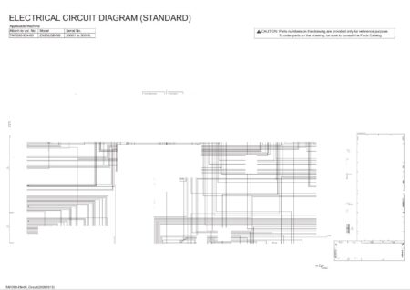
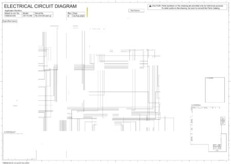
Wiring Diagram
3TNV88C, 3TNV86CT, 3TNV86CHT, 4TNV88C, 4TNV86CT, 4TNV86CHT, 4TNV98C, 4TNV98C-C, 4TNV98CT, 4TNV98CT-C, 3TN88C, 3TN86CT, 3TN86CHT (MD1), 4TN88C, 4TN86CT, 4TN86CHT (MD1), 4TN98C, 4TN98CT
3TN86CHT (MD1, EDC17), 4TN86CHT (MD1, EDC17), 4TN86DHT (MD1, EDC17)
List of Terminal
3TNV88C, 3TNV86CT, 3TNV86CHT, 4TNV88C, 4TNV86CT, 4TNV86CHT, 4TNV98C, 4TNV98C-C, 4TNV98CT, 4TNV98CT-C, 3TN88C, 3TN86CT, 3TN86CHT (MD1), 4TN88C, 4TN86CT, 4TN86CHT (MD1), 4TN98C, 4TN98CT
3TN86CHT (MD1, EDC17), 4TN86CHT (MD1, EDC17), 4TN86DHT (MD1, EDC17)
Coupler Diagram
3TNV88C, 3TNV86CT, 3TNV86CHT, 4TNV88C, 4TNV86CT, 4TNV86CHT, 4TNV98C, 4TNV98C-C, 4TNV98CT, 4TNV98CT-C, 3TN88C, 3TN86CT, 3TN86CHT (MD1), 4TN88C, 4TN86CT, 4TN86CHT (MD1), 4TN98C, 4TN98CT
3TN86CHT (MD1, EDC17), 4TN86CHT (MD1, EDC17), 4TN86DHT (MD1, EDC17)
Electric Wiring
Electric Wiring Precautions
Electrical Wire Resistance
Battery Cable Resistance
Electrical Wire Sizes – Voltage Drop
Conversion of AWG to European Standards
Failure Diagnosis
Special Service Tools
Troubleshooting by Measuring Compression Pressure
Compression Pressure Inspection Procedures
Attaching the Injector
Engine Speed and Compression Pressure (Use for Reference)
Measured Value and Troubleshooting
Quick Reference Table for Troubleshooting
Failure Diagnostic List

There are no reviews yet.