Hitachi ZX38U-6 Excavator TADS50-EN-01 (2023.12.04) (Preview)
TADS50-EN-01
INTRODUCTION
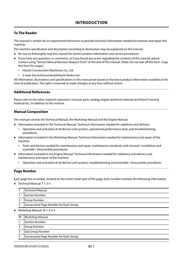
To The Reader
Additional References
Manual Composition
Page Number
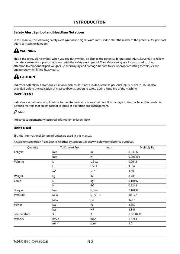
Safety Alert Symbol and Headline Notations
Units Used
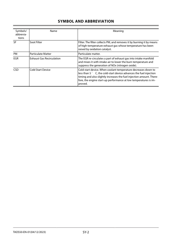
SYMBOL AND ABBREVIATION
Symbols and abbreviations
CONTRASTING LIST OF PART NAME
Contrasting List of Part Name between Technical Manual and Parts Catalog
SAFETY
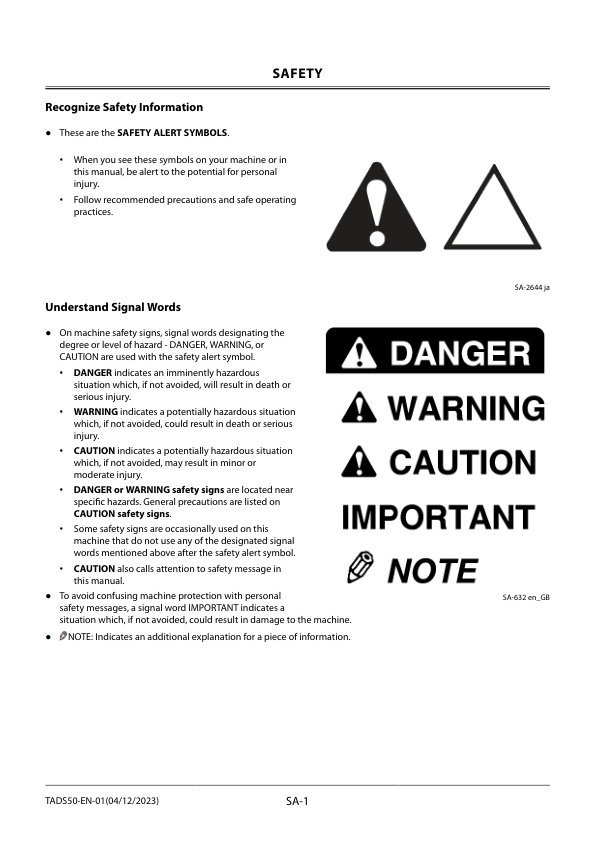
Recognize Safety Information
Understand Signal Words
Follow Safety Instructions
Prepare for Emergencies
Wear Appropriate Clothing
Protect Against Noise
Inspect Machine
General Precautions for the Cab
Use Handholds and Steps
Adjust the Operator’s Seat
Ensure Safety Before Leaving or Standing up from Operator’s Seat
Fasten Your Seat Belt
Move and Operate Machine Safely
Operate Only from Operator’s Seat
Jump Starting
Keep Riders off Machine
Precautions for Operations
Investigate Job Site Beforehand
Install OPG
Restriction of Attachment Installation
Provide Signals for Jobs Involving Multiple Machines
Confirm Direction of Machine to Be Driven
Drive Machine Safely
Avoid Injury from Rollaway Accidents
Avoid Injury from Back-Over and Swing Accidents
Keep People Clear from Working Area
Never Position the Bucket Over Anyone
Avoid Undercutting
Avoid Tipping
Never Undercut a High Bank
Dig with Caution
Operate with Caution
Avoid Power Lines
Precautions for Lightning
Lifting Application
Protect Against Flying Debris
Park Machine Safely
Handle Fluids Safely−Avoid Fires
Transport Safely
Practice Safe Maintenance
Warn Others of Service Work
Support Machine Properly
Stay Clear of Moving Parts
Prevent Parts from Flying
Avoid Injury from Attachment Falling Accident
Prevent Burns
Replace Rubber Hoses Periodically
Avoid High-Pressure Fluids
Prevent Fires
Evacuating in Case of Fire
Beware of Exhaust Fumes
Precautions for Welding and Grinding
Avoid Heating Near Pressurized Fluid Lines
Avoid Applying Heat to Lines Containing Flammable Fluids
Precautions for Handling Accumulator and Gas Damper
Remove Paint Before Welding or Heating
Beware of Asbestos and Silicon Dust and Other Contamination
Prevent Battery Explosions
Service Air Conditioning System Safely
Handle Chemical Products Safely
Dispose of Waste Properly
Never Ride Attachment
Precautions for Communication Terminal
Precautions for Communication Terminal Equipment
Compliance with CE Rules and Regulations (EU)
Precautions about Operator’s Seat Protections when Overturned (4-pillar Canopy or Cab Models)
Before Returning the Machine to the Customer
SECTION AND GROUP CONTENTS
CONTENTS
GENERAL
Specifications
Specifications of ZX38U-6
Working Ranges of ZX38U-6
Component Layout
Main Component
Electrical System (Overview)
Electrical System (Relays)
Electrical System (Relays) (Cab Models)
Electrical System (Monitor, Switches)
Electrical System (Battery Chamber)
Engine
Swing Device
Travel Device
Control Valve
2-Spool Solenoid Valve Unit
Torque Control Solenoid Valve (Only Machine with Air Conditioner (Option) Attached)
Port Layout of Control Valve (Main Circuit)
Port Layout of Control Valve (Pilot Circuit)
Floor Wire Harness (ZX33U-6: Up to Serial No. 053309 (excluding Serial No. 052933), ZX38U-6: Up to Serial No. 061367 (excluding Serial No. 061231))
Floor Wire Harness (ZX33U-6: Serial No. 052933, Serial No. 053310 and Up, ZX38U-6: Serial No. 061231, Serial No. 061368 and Up
Main Harness
Light Harness (Halogen)
Light Harness (LED)
Cab Intermediate Wire Harness (ZX33U-6: Up to Serial No. 053309 (excluding Serial No. 052933), ZX38U-6: Up to Serial No. 061367 (excluding Serial No. 061231))
Cab Intermediate Wire Harness (ZX33U-6: Serial No. 052933, Serial No. 053310 and Up, ZX38U-6: Serial No. 061231, Serial No. 061368 and Up
Air Conditioner Floor Harness
HEATER HARNESS
AIR CONDITIONER COMPRESSOR HARNESS
Component Specifications
Specifications of Engine
Specifications of Engine Accessories
Specifications of Hydraulic Component
Specifications of Electrical Component
SYSTEM
Control System
Outline of Control System
Engine Control
Engine Control Dial Control
Auto-Idle Control
Idle Speed-Up Control
ECO Mode Control
Engine Speed Control
EGR Control
CSD Control
Starter Restraining Control
Pump Control
Power Decrease Control (Only Machine with Air Conditioner)
Valve Control
Auxiliary Flow Rate Selection Control
AUX Function Lever (AFL) Control (Option)
Other Control
Overload Alarm Control
Hydraulic System
Outline of Hydraulic System
Pilot Circuit of Hydraulic System
Operation Control Circuit
Travel Motor Displacement Angle Control Circuit
Swing Parking Brake Release Circuit
Pump Control Circuit (Machine with Air Conditioner)
Main Circuit of Hydraulic System
Neutral Circuit
Single Operation Circuit
Combined Operation Circuit (Combined Operation of Travel and Front Attachment)
Operation of Flow Rate Combiner Selector Valve (Hydraulic System)
Electrical System
Outline of Electrical System
Main Circuit of Electrical System
Electric Power Circuit (Key Switch: OFF)
CAN Circuit
Electric Power Circuit (Key Switch: ON)
Preheating Circuit (Key Switch: ON)
Starting Circuit (Key Switch: START)
Charging Circuit (Key Switch: ON)
Pilot Shut-Off Circuit (Key Switch: ON)
Engine Stop Circuit (Key Switch: OFF)
COMPONENT OPERATION
Pump device
Outline of Pump Device
Outline of Main Pump P1 and Main Pump P2
Outline of Main Pump P3 and Pilot Pump
Output Power Control Operation
Swing Device
Outline of Swing Device
Outline of Swing Reduction Gear
Outline of Swing Motor
Outline of Swing Parking Brake
Operation of Swing Parking Brake (When Brake is Released)
Operation of Swing Parking Brake (When Brake is Applied)
Outline of Valve Unit
Operation of Make-Up Valve
Outline of Swing Relief Valve
Low-Pressure Relief Operation (Shockless Function) of Swing Relief Valve
High-Pressure Relief Operation (Overload Prevention) of Swing Relief Valve
Relief Operation of Swing Relief Valve (Piston Quick Return)
Control Valve
Outline of Control Valve
Components in Control Valve
Main Circuit of Control Valve
Pilot Signal Circuit of Control Valve
Outline of Arm Regenerative Valve
Outline of Boom Anti-Drift Valve
Operation of Boom Anti-Drift Valve (When Boom Spool is In Neutral)
Operation of Boom Anti-Drift Valve (When Operating Boom Raise)
Operation of Boom Anti-Drift Valve (When Operating Boom Lower)
Outline of Flow Combiner Valve
Outline of Single Flow/Combination Selector Valve
Outline of Main Relief Valve
Operation of Main Relief Valve
Outline of Overload Relief Valve
Relief Operation of Overload Relief Valve
Make-Up Operation of Overload Relief Valve
Operation of Make-Up Valve
Pilot Valve
Outline of Pilot Valve
Outline of Front Attachment/Swing Pilot Valve
Outline of Travel Pilot Valve
Outline of Boom Swing, Blade and Auxiliary Pilot Valves
Operation of Front Attachment/Swing and Travel Pilot Valve
When Front Attachment/Swing and Travel Pilot Valves are in Neutral (Output Curve: A to B)
During Metering or Decompressing of Front Attachment/Swing and Travel Pilot Valves (Output Curve: C to D)
Full Stroke of Travel Pilot Valve (Output Curve: E to F)
Operation of Boom Swing, Blade and Auxiliary Pilot Valves
When Boom Swing, Blade and Auxiliary Pilot Valves in Neutral (Output Curve: A to B)
During Metering or Decompressing of Boom Swing, Blade and Auxiliary Pilot Valves (Output Curve: C to D)
Outline of Shockless Function (Only Travel Pilot Valve)
Operation of Shockless Function
Travel Device
Outline of Travel Device
Outline of Travel Reduction Gear
Outline of Travel Motor
Operation of Travel Motor
Outline of Parking Brake
When Parking Brake is Released
When Parking Brake is Operated
Outline of Travel Brake Valve
Operation of Counterbalance Valve (During Travel)
Operation of Counterbalance Valve (When Descending a Slope)
Operation of Travel Mode Selector Valve (Slow Speed Operation)
Operation of Travel Mode Selector Valve (Fast Speed Operation)
Operation of Travel Mode Selector Valve (When Engine Stops)
Auto Swash Angle Control
Others (Upperstructure)
Outline of 2-Spool Solenoid Valve Unit
Operation of Pilot Shut-Off Solenoid Valve (Pilot Shut-Off Lever: LOCK Position)
Operation of Pilot Shut-Off Solenoid Valve (Pilot Shut-Off Lever: UNLOCK Position)
Operation of Travel Mode Selector Solenoid Valve (Slow Speed Position)
Operation of Travel Mode Selector Solenoid Valve (Fast Speed Position)
Operation of Pilot Relief Valve
Outline of Torque Control Solenoid Valve (Only Machine with Air Conditioner (Option) Attached)
Torque Control Solenoid Valve Operation (Only Machine with Air Conditioner (Optional)) (Air Conditioner Switch OFF)
Torque Control Solenoid Valve Operation (Only Machine with Air Conditioner (Optional)) (Air Conditioner Switch ON)
Operation of Hose Rupture Valve (When Control Lever is in Neutral)
Operation of Hose Rupture Valve (During Boom Lower Operation)
Others (Undercarriage)
Outline of Swing Bearing
Outline of Center Joint
Outline of Track Adjuster
OPERATIONAL PERFORMANCE TEST
Performance Test
Operational Performance Tests
Preparation for Performance Tests
Standard
Operational Performance Standard Table
Engine System Performance Standards
Travel System Performance Standards
Swing System Performance Standards
Front Attachment System Performance Standards
Lever System Performance Standards
Combined Operation System Performance Standards
Components System Performance Standards
Main Pump P1 and Main Pump P2 P-Q Diagram
Engine Control Dial Activating Range
Low Pressure Sensor Activating Range
Engine Test
Engine Speed
Machine Performance Test
Travel Speed
Track Revolution Speed
Mistrack Check
Travel Parking Leakage
Swing Speed
Swing Function Drift Check
Swing Motor Leakage
Maximum Swingable Slant Angle
Swing Bearing Play
Hydraulic Cylinder Cycle Time
Dig Function Drift Check
Control Lever Operating Force
Control Lever Stroke
Combined Operation of Boom Raise and Swing Function Check
Clearance of Front Attachment Connecting Part
Component Test
Primary Pilot Pressure
Secondary Pilot Pressure
Main Relief Set Pressure
Relief Pressure (When Relieving Swing)
Overload Relief Valve Set Pressure
Pump Driving Torque
Swing Motor Drainage
Travel Motor Drainage
TROUBLESHOOTING
Diagnosing Procedure
Introduction
Diagnosis Procedure
Electrical System Inspection
Precautions for Inspection and Maintenance
Instructions for Disconnecting Connectors
Instructions for Removing Relays
Fuse Inspection
Fuse Connection Destination
Slow Blow Fuse Inspection
Battery Voltage Check
Alternator Check
Continuity Check
Voltage Inspection Method
Voltage and Current Measurement of 5-Volt Circuits
Check by False Signal
Removal of Monitor Controller
Installation of Monitor Controller
Removal of E-ECU
Installation of E-ECU
Mounting Position of Fuel Sensor
Mounting Position of Boom Bottom Pressure Sensor
Mounting Position of Auto Idle Pressure Sensor
Monitor
Basic Screen Monitor
Operating Procedures of Service Menu
How to Display Service Menu
Monitoring
Monitoring List
Setting
List of Monitor Setting Item
Issued Warning Record
List of Alarm
Engine Fault Code List
Inspection of Fuel Gauge, Battery Voltage, Hour Meter, and Destination Number
Fuel Gauge
Coolant Temperature Gauge
Factory Setting
e-Service
Overview of e-Service
List of Operation Data
Communication System
Troubleshooting A
Troubleshooting A (Base Machine Diagnosis By Using Fault Codes) Procedure
Contents of Troubleshooting A
Fault Code List
Fault Code W: 1304
Fault Code W: 1310
Fault Code W: 2304
Fault Code W: 2306
Fault Code W: 2307
Troubleshooting B
Troubleshooting B (Machine Diagnosis by Using Trouble Symptom) Procedure
Contents of Troubleshooting B
Identification Symbol of Troubleshooting B
E-1 Starter does not rotate.
E-2 Even if starter rotates, engine does not start.
E-3 Auto-idle system is faulty.
E-4 Engine is difficult to start at low temperature. (During cold weather or in cold districts, engine is difficult to start or does not start even if pre-heated.)
E-5 ECO mode is faulty.
A-1 All actuator speeds are slow and power is weak.
A-2 All actuators do not work.
A-3 Actuator does not stop even if control lever is set to neutral.
A-4 Actuator does not stop even if control lever is set to neutral. (Amount of drift is large.)
A-5 Front attachment is not operated during combined operation of travel and front attachment.
F-1 All front attachment actuator power are weak.
F-2 Some cylinders are not operated or speeds are slow.
F-3 Arm roll-in operation speed is slow.
F-4 Front attachment drifts remarkably.
F-5 When boom raise or arm roll-out is operated, boom or arm starts to move after moving slightly down.
F-6 Boom swing is not operated or moves slowly.
S-1 Swing speed is slow or is not operated.
S-2 Swing drifts remarkably when swinging is stopped.
T-1 Machine does not travel, travels slowly, or power is weak.
T-2 Fast travel can not be selected. Travel mode does not change from slow speed mode to fast speed mode.
T-3 Slow travel can not be selected. Travel mode does not change from fast mode to slow mode.
T-4 One side travel is not operated or travel speed is slow. Machine mistracks.
BL-1 Blade is not operated or moves slowly.
How to Lowering Boom When Emergency and When Engine Stops
Air Conditioner
Outline of Air Conditioner
Troubleshooting of Air Conditioner
Faulty cooling
Air conditioner is not operated. Air conditioner control panel does not light at all.
Air vent air temperature control is impossible.
Compressor clutch is not turned ON.
Blower motor does not rotate.
Air flow volume (I) and (II) are not shifted. (Air flow volume (I) and (II) are the same.)
Air flow volume (I) and (III) are not shifted. (Air flow volume (I) and (III) are the same.)
Air flow volume (II) and (III) are not shifted. (Air flow volume (II) and (III) are the same.)
Air flow volume (I), (II) and (III) are not shifted. (Air flow volume (I), (II) and (III) are the same.)
Air vent cannot be shifted.
Air vent selection is impossible.
Work after Replacing Components
Necessity of Purging
Procedures for Charging Air Conditioner with Refrigerant
Warm-up Operation
AIR CONDITIONER TROUBLE REPORT
SERVICE MANUAL REVISION REQUEST FORM
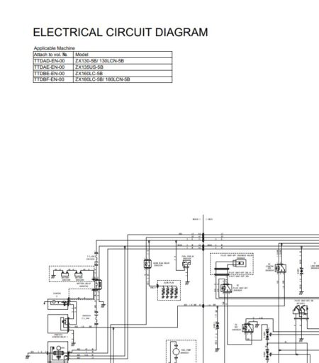
The Attached Diagram List



There are no reviews yet.