Bobcat E165 B53W11001 & Up 7407615 (Preview)
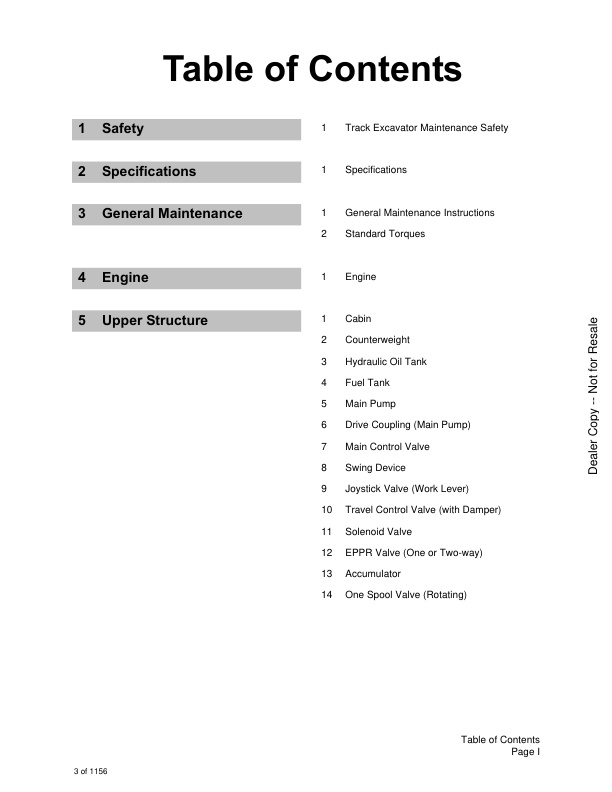
Table of Contents
Safety
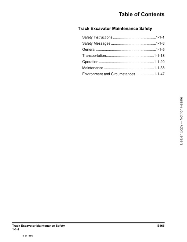
Track Excavator Maintenance Safety
Safety Instructions
Safety Messages
General
Safe Operation is Operator’s Responsibility
Know Your Machine
Proper Work Tools and Attachments
Pressurized Fluids
Flying or Falling Objects
Personal Protective Equipment (PPE)
Correction of Machine Problems
Crushing and Cutting
Hot Coolant and Oils – Burn Prevention
Fire and Explosion Prevention
Fire Extinguisher and First-aid Kit (Emergency Medical Kit)
Electrical System and Electrical Shock
Roll-over Protective Structure (ROPS)
Transportation
Obey State and Local Over-the-Road Regulations
Loading and Unloading
Transporting Machine
Operation
Before Engine Starting
Work Site
Mounting/Dismounting
Cleaning
Operator Station
Seat Belt
Visibility Information
Boost Starting or Charging Engine Batteries
Starting Engine
Swinging or Traveling
Lifting and Digging
Operation on Slopes
Towing
Attachment
Engine Stop
Parking Machine
Preservation/Storing Machine
Maintenance
Cleaning
Fire and Explosion Prevention
Burn Prevention
Lock Inspection Covers
Working on Machine
Track Tension Adjustments
Supports and Blocking for Work Equipment
High-pressure Lines, Tubes and Hoses
Battery
Environment and Circumstances
Work Site Areas Requiring Extra Caution
High-voltage Cables
Underground Operation
Working in Water
Working in Contaminated Environment
Exhaust Ventilation
Asbestos Information
Silica Dust Information
Disposal of Hazardous Materials
Sound
Vibration Information
Specifications
Specifications
Safety Instructions
General Description
Component Locations
Overall Dimensions
Working Range
General Specifications
Approximate Weight of Workload Materials
Performance Tests
Purpose of Performance Tests
Kinds of Tests
Performance Standards
Precautions for Evaluation of Test Data
Definition of “Performance Standard”
Preparation for Performance Tests
The Machine
Test Area
Precautions
Make Precise Measurement
Operational Performance Standard Table
Operational Performance Test
Hydraulic Cylinder Cycle Time
Travel Speed
Track Revolution Speed
Mistrack Check
Swing Speed
Swing Function Drift Check
Cylinder Creep
General Maintenance
General Maintenance Instructions
Safety Instructions
Welding Precautions and Instructions
Hydraulic System – General Precautions
General Precautions
Hydraulic System Cleanliness and Oil Leaks
Maintenance Precautions for Hydraulic System Service
Oil Leakage Precautions
Cleaning and Inspection
General Instructions
Bearing Inspection
Standard Torques
Safety Instructions
Torque Values for Standard Metric Fasteners
Torque Values for Standard U.S. Fasteners
Type 8 Phosphate Coated Hardware
Torque Values for Hose Clamps
ORFS Swivel Nut Recommended Torque
Torque Values for Split Flanges
Torque Wrench Extension Tools
Torque Multiplication
Other Uses for Torque Wrench Extension Tools
Tightening Torque Specifications (Metric)
Engine
Engine
Safety Instructions
Overview
General Information
Major Component Location
Engine Identification
Engine Lifting
Maintenance and Storage
Engine Specification
General Specification
Engine Performance Curves
Basic Engine
Cylinder Block
Cylinder Head
Valve Mechanism Cover
Crankcase Breather
Flywheel and Flywheel Housing
Actuating System
Pistons, Rings, and Connecting Rods
Crankshaft
Gears and Timing Gear Case
Camshaft
Rocker Shaft
Lubricant System
Overview
Engine Oil Pump
Engine Oil Filter
Engine Oil Pan
Engine Oil Pressure – Test
Excessive Bearing Wear – Inspect
Excessive Engine Oil Consumption – Inspect
Increased Engine Oil Temperature – Inspect
Cooling System
Overview
Water Pump
Water Temperature Regulator
Engine Oil Cooler
Piston Cooling Jets
Fuel System
Overview
High-pressure Fuel System
Water Separator & Pre Fuel Filter (Fuel Prefilter)
Main Fuel Filter
Fuel Injection Pump
Fuel Injection Lines
Fuel Injectors
Fuel System – Inspect
Air in Fuel – Test
Finding Top Center Position for No. 1 Piston
Fuel Injection Timing – Check
Fuel Quality – Test
Fuel System – Prime
Cleanliness of Fuel System
Air Inlet and Exhaust System
Exhaust System
Clean Emissions Module (Diesel Oxidation Catalyst (DOC) and Selective Catalytic Reduction (SCR) System)
DEF Dosing Control System
Electrical System
Electrical Control System
Sensor Locations for the Engine
Sensor Locations for the Clean Emissions Module
Electronic Control Module (ECM)
Electric Component – Remove and Install
Upper Structure
Cabin
Safety Instructions
Cabin Identification
Roll-over Protective Structure (ROPS)
Removal
Installation
Completing work
Removal and Installation of Cabin Glass
Removal of Cabin Glass
Installation of Cabin Glass
Installation of Upper Door Glass
Installation of Upper Front Glass
Counterweight
Safety Instructions
General
Warning for Counterweight and Front Attachment Removal
Removal
Installation
Hydraulic Oil Tank
Safety Instructions
General
Specification
Air Breather
Removal
Installation
Completing Work
Fuel Tank
Safety Instructions
General
Specification
Removal
Installation
Completing Work
Main Pump
Safety Instructions
Axial Piston Pump
General Description
Specifications
Overview
Hydraulic Circuit
Tools
Tightening Torque
Removal
Installation
Completing Work
Disassembly
Reassembly
Troubleshooting
Maintenance Instructions
Regulator
Functional Explanation
Adjustment
Pilot Gear Pump
Specification
Port and Hydraulic Circuit
Precaution
Drive Coupling (Main Pump)
Safety Instructions
General
Specification
Disassembly
Reassembly
Main Control Valve
Safety Instructions
General
Specification
Overview
Cautions for Operation
Precaution
Removal
Installation
Completing Work
Disassembly
Cautions on Disassembly
Sequence of Disassembly
cleaning and inspection
Cleaning
Inspection
Reassembly
Caution on Assembly
Sequence of Reassembly
Troubleshooting and adjustment
Troubleshooting
Adjusting Relief Valve
Swing Device
Safety Instructions
General
Specification
Overview
Cautions for Operation
Precaution
Tools for Disassembly and Assembly
Tightening Torque
Removal
Installation
Completing work
Disassembly
Swing Motor
Swing Reduction Gear
Reassembly
Swing Motor
Swing Reduction Gear
Troubleshooting
General Instructions
Examination of Hydraulic Motor
Troubleshooting
Maintenance Instructions
Replacement Standard of Worn Parts
Standard of Sliding Surface Correction
Joystick Valve (Work Lever)
Safety Instructions
General
Specifications
Overview
Removal
Installation
Completing work
Disassembly
Reassembly
Travel Control Valve (with Damper)
Safety Instructions
General
Specification
Overview
Removal
Installation
Completing Work
Disassembly
Reassembly
Troubleshooting
Solenoid Valve
Safety Instructions
General
Specification
Overview
Disassembly and Reassembly
Troubleshooting
EPPR Valve (One or Two-way)
Safety Instructions
General
Specification
Overview
Hydraulic Circuit
Troubleshooting
Accumulator
Safety Instructions
General
Specifications
One Spool Valve (Rotating)
Safety Instructions
General
Specification
Overview
Disassembly and Assembly
General Cautions
Replacement of Spool
Replacement of Main Relief Valve
Replacement of Overload Relief Valve
Replacement of Sub-Block
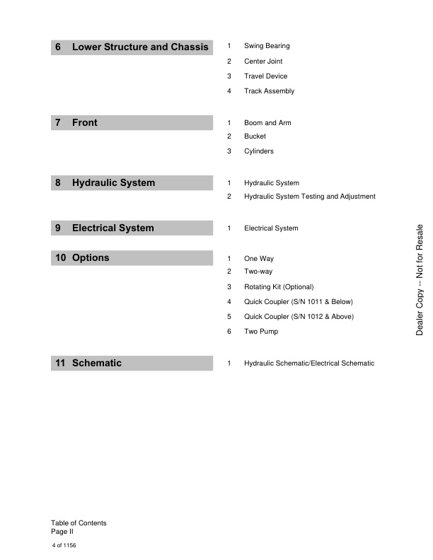
Lower Structure and Chassis
Swing Bearing
Safety Instructions
General
General Description
Maintenance Guidelines
Disassembly
Reassembly
Center Joint
Safety Instructions
General
General Description
Overview
Removal
Installation
Completing Work
Disassembly
Reassembly
Troubleshooting, Testing and Adjustment
Inspection
Testing
Travel Device
Safety Instructions
General
Specification
Overview
Cautions for Operation
Precaution
Tools List for Disassembly and Reassembly
Removal
Installation
Completing Work
Disassembly
Preparation
General Precautions
Disassembly Procedure
Reassembly
Preparation
General Cautions
Reassembly Procedure
Matters to Check after Assembly
Performance Test
Troubleshooting
Track Assembly
Safety Instructions
General
Track Tension
Track Shoes and Links
Track Removal
Track Installation
Wear Limits and Tolerances
Sprocket
Wear Limits and Tolerances
Front Idler
Overview
Front Idler Disassembly
Front Idler Reassembly
Wear Limits and Tolerances
Upper Roller
Overview
Upper Roller Removal
Upper Roller Disassembly
Upper Roller Reassembly
Wear Limits and Tolerances
Lower Roller
Overview
Lower Roller Removal
Lower Roller Installation
Lower Roller Disassembly
Lower Roller Reassembly
Wear Limits and Tolerances
Track Adjuster
Disassembly
Assembly
Front
Boom and Arm
Safety Instructions
Specifications
Removal
Arm Removal
Boom Removal
Installation
Arm Installation
Boom Installation
Completing Work
Bucket
Safety Instructions
Bucket Tooth Inspection and Replacement
Bucket O-ring Replacement
Installation
Bucket Detaching and Reversal
Detaching
Reversal
Cylinders
Safety Instructions
General
General Description
Specification
Seal of Cylinder
Special Tools and Materials
Piston Nut
Piston Jig
Steel Bushing Jig
Dust Wiper Jig
Slipper Seal Jig
Slipper Seal Straightening Jig
Rod Bushing (DD-bushing) Pushing-in Jig
Disassembly
Reassembly
Troubleshooting
Hydraulic System
Hydraulic System
Safety Instructions
Hydraulic System
General Description
Hydraulic Schematic
General Description
Hydraulic Component and Oil Flow
Hydraulic Components
Main Oil Circuit
Pilot Oil Circuit
Return Oil Circuit
Safety Lever Valve Operation
Power Up Valve Operation
Swing Brake Release Operation
Travel Forward and Backward Operation
Travel High-speed Valve Operation
Boom Up Operation
Boom Down Operation
Easy Boom Operation
Arm Dump Operation
Arm Crowd Operation
Bucket Dump Operation
Bucket Crowd Operation
Combined Bucket Crowd and Boom Up Operation
Combined Travel and Boom, Arm, Bucket or Swing Operation
Two Pump Operation
Hydraulic System Testing and Adjustment
Safety Instructions
Procedural Troubleshooting Baseline Recommendations
Initial Checks and Tests to Establish Operating Condition of the Excavator
Pilot Pressure
Adjustment and Testing
Power Mode Valve
Current Signal and Hydraulic Pressure Adjustments
Pressure Up Valve
Checks and Adjustments
Pump Input Power Control
Pump Regulator Adjustment
Flow Meter and Flow Meter Kit Installation and Testing
Swing System Troubleshooting
Precautions/Initial Checks
Swing Relief Valve Checking and Adjustment
Electrical System
Electrical System
Safety Instructions
Introduction
Electrical Supply System
Engine Starting Circuit
Start Operation
After Start
Engine Stop
Charging System
Monitoring System
Instrument Panel
Functional Check
Monitoring System Schematic
Operation
Instruments
Warning and Indicator Lights
Indication of Warning Lights
Indication of Multifunction Gauge
Initial Operation
Graphic Information Area Display
Overview
Main Menus for the Graphic Display Area
Menu Selector Buttons
User Menu
User Menu – Access and Escape Methods
Special Menu
Entering/Accessing and Exiting/Escaping Menus
Special Menu Selections
Failure Code
Failure Code at Machine
Failure Code at Engine Side
FMIs (Failure Mode Identifier)
Electronic Hydraulic Control System (EPOS)
Control System Schematic
Power Plus Mode Control
Operation
Power Mode Control
Smart Power Control (SPC)
Operation
Engine Control System
Engine Control Dial
Engine Control
Automatic Deceleration Control (Auto Idle Control)
Engine Overheat Protection System
Power Boost Mode
Operation
Power Boost Control
Automatic Travel Speed Control
Automatic Travel Speed Control
Water in Fuel Warning System
Operation
Self-diagnostic Function
EPOS Controller
Air Conditioner System
Outline
Internal and External Filters
Air-Conditioning System Layout
Air Conditioner/Heater Circuit Diagram
Air Conditioner/Heater Unit
Ambient Air Temperature Sensor
Sun Sensor
Control Panel
Receiver Dryer
Troubleshooting
Refrigerant System Repairs
Refrigerant Safe Handling Procedures
Repair and Replacement Procedure
Refrigerant Recovery
Vacuuming Refrigerant System
Leakage Check
Refrigerant Charging
Inspecting System For Leakage
Wiper System
Wiper Circuit
Wiper Operation
Lighting System
Lighting System Circuit Diagram
Kind of Light
Operation
Overload Warning Device
Overload Warning Device Circuit Diagram
Audio Controller
Audio Controller Circuit Diagram
Options
One Way
Safety Instructions
General
General Description
Theory of Operation
Hydraulic Circuit
Caution for Installation
Installation Procedure
After Installation Precautions
Air Bleeding
Completing Work
Two-way
Safety Instructions
General
General Description
Theory of Operation
Structure
Hydraulic Circuit
Caution for Installation
Installation Procedure
After Installation Precautions
Air Bleeding
Completing Work
Rotating Kit (Optional)
Safety Instructions
General
General Description
Theory of Operation
Structure
Hydraulic Circuit
Caution for Installation
Installation Procedure
After Installation Precautions
Air Bleeding
Completing Work
Quick Coupler (S/N 1011 & Below)
Safety Instructions
General
General Description
Theory of Operation
Hydraulic Circuit
Caution for Installation
Quick Coupler Operation
Securing Work Tool
Attaching Quick Coupler to Excavator
Releasing the Work Tool
Quick Coupler (S/N 1012 & Above)
Safety Instructions
General
General Description
Theory of Operation
Hydraulic Circuit
Caution for Installation
Quick Coupler Operation
To Engage Attachment
To Release Attachment
Two Pump
Safety Instructions
General
General Description
Theory of Operation
Hydraulic Circuit
Caution for Installation
Installation Procedure
After Installation Precautions
Air Bleeding
Schematic
Hydraulic Schematic / Electrical Schematic
E165 Hydraulic Schematic
E165 Electrical Schematic





There are no reviews yet.