Hitachi ZW65-6, ZW75-6, ZW95-6 Wheel loader WPSY-EN-00 (Preview)
ZW
65-6 75-6 95-6
Wheel loader
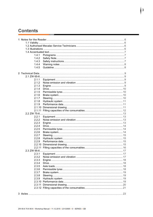
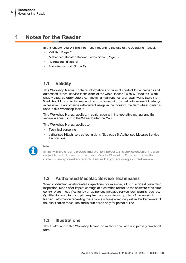
1 Notes for the Reader
1.1 Validity
1.2 Authorised Mecalac Service Technicians
1.3 Illustrations
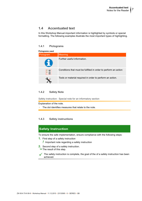
1.4 Accentuated text
1.4.1 Pictograms
1.4.2 Safety Note
1.4.3 Safety instructions
1.4.4 Warning notes
1.4.5 Guideline
2 Technical Data
2.1 ZW 65-6
2.1.1 Equipment
2.1.2 Noise emission and vibration
2.1.3 Engine
2.1.4 Drive
2.1.5 Permissible tyres
2.1.6 Brake system
2.1.7 Steering
2.1.8 Hydraulic system
2.1.9 Performance data
2.1.10 Dimensional drawing
2.1.11 Filling capacities of the consumables
2.2 ZW 75-6
2.2.1 Equipment
2.2.2 Noise emission and vibration
2.2.3 Engine
2.2.4 Drive
2.2.5 Permissible tyres
2.2.6 Brake system
2.2.7 Steering
2.2.8 Hydraulic system
2.2.9 Performance data
2.2.10 Dimensional drawing
2.2.11 Filling capacities of the consumables
2.3 ZW 95-6
2.3.1 Equipment
2.3.2 Noise emission and vibration
2.3.3 Engine
2.3.4 Drive
2.3.5 Axle loads
2.3.6 Permissible tyres
2.3.7 Brake system
2.3.8 Steering
2.3.9 Hydraulic system
2.3.10 Performance data
2.3.11 Dimensional drawing
2.3.12 Filling capacities of the consumables
3 Axles
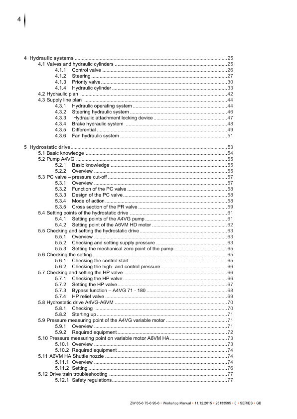
4 Hydraulic systems
4.1 Valves and hydraulic cylinders
4.1.1 Control valve
4.1.2 Steering
4.1.3 Priority valve
4.1.4 Hydraulic cylinder
4.1.4.1 Disassembly diagrams – Hydraulic cylinder
4.1.4.2 Gasket arrangement for hydraulic cylinder with end position damping
4.2 Hydraulic plan
4.3 Supply line plan
4.3.1 Hydraulic operating system
4.3.2 Steering hydraulic system
4.3.3 Hydraulic attachment locking device
4.3.4 Brake hydraulic system
4.3.5 Differential
4.3.6 Fan hydraulic system
5 Hydrostatic drive
5.1 Basic knowledge
5.2 Pump A4VG
5.2.1 Basic knowledge
5.2.2 Overview
5.3 PC valve – pressure cut-off
5.3.1 Overview
5.3.2 Function of the PC valve
5.3.3 Design of the PC valve
5.3.4 Mode of action
5.3.5 Cross section of the PR valve
5.4 Setting points of the hydrostatic drive
5.4.1 Setting points of the A4VG pump
5.4.2 Setting point of the A6VM HD motor
5.5 Checking and setting the hydrostatic drive
5.5.1 Overview
5.5.2 Checking and setting supply pressure
5.5.2.1 Pump A4VG 71
5.5.2.2 Pump A4VG 56
5.5.3 Setting the mechanical zero point of the pump
5.6 Checking the setting
5.6.1 Checking the control start
5.6.2 Checking the high- and control pressure
5.7 Checking and setting the HP valve
5.7.1 Checking the HP valve
5.7.2 Setting the HP valve
5.7.3 Bypass function – A4VG 71 – 180
5.7.4 HP relief valve
5.7.4.1 Overview
5.7.4.2 Setting the HP relief valve of the A4VG 40-56
5.7.4.3 Bypassing the HP relief valve for towing the machines
5.8 Hydrostatic drive A4VG-A6VM
5.8.1 Checking
5.8.2 Starting up
5.9 Pressure measuring point of the A4VG variable motor
5.9.1 Overview
5.9.2 Required equipment
5.10 Pressure measuring point on variable motor A6VM HA
5.10.1 Overview
5.10.2 Required equipment
5.11 A6VM HA Shuttle nozzle
5.11.1 Overview
5.11.2 Setting
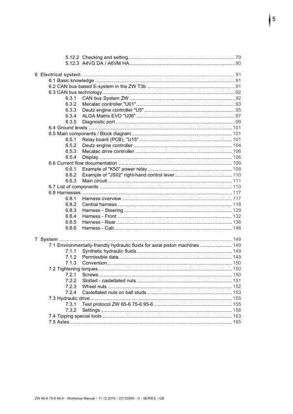
5.12 Drive train troubleshooting
5.12.1 Safety regulations
5.12.2 Checking and setting
5.12.3 A4VG DA / A6VM HA
5.12.3.1 A4VG DA / A6VM HA – Overview
5.12.3.2 Possible causes of fault and rectification
5.12.3.3 Possible causes of fault and rectification
6 Electrical system
6.1 Basic knowledge
6.2 CAN bus-based E-system in the ZW T3b
6.3 CAN bus technology
6.3.1 CAN bus System ZW
6.3.2 Mecalac controller “U01”
6.3.3 Deutz engine controller “U5”
6.3.4 ALGA Matrix EVO “U06”
6.3.5 Diagnostic port
6.4 Ground levels
6.5 Main components / Block diagram
6.5.1 Relay board (PCB), “U15”
6.5.2 Deutz engine controller
6.5.2.1 Function description
6.5.2.2 Interface
6.5.2.3 Error messages
6.5.3 Mecalac drive controller
6.5.3.1 Function description
6.5.3.2 Error messages
6.5.4 Display
6.5.4.1 Function description
6.5.4.2 Display flow diagram
6.6 Current flow documentation
6.6.1 Example of “K50” power relay
6.6.2 Example of “JS02” right-hand control lever
6.6.3 Main circuit
6.7 List of components
6.8 Harnesses
6.8.1 Harness overview
6.8.2 Central harness
6.8.3 Harness – Steering
6.8.4 Harness – Front
6.8.5 Harness – Rear
6.8.6 Harness – Cab
7 System
7.1 Environmentally-friendly hydraulic fluids for axial piston machines
7.1.1 Synthetic hydraulic fluids
7.1.2 Permissible data
7.1.3 Conversion
7.2 Tightening torques
7.2.1 Screws
7.2.2 Slotted – castellated nuts
7.2.3 Wheel nuts
7.2.4 Castellated nuts on ball studs
7.3 Hydraulic drive
7.3.1 Test protocol ZW 65-6 75-6 95-6
7.3.2 Settings
7.4 Tipping special tools
7.5 Axles
K3 Spicer Achse.pdf
Seiten aus K04 Achse MO111F30.pdf
K04 Achse MO111F30.pdf
Leere Seite
There are no reviews yet.