


Technical Manual Hitachi ZX48U-5A Excavator TAEA-EN-01 (2022.12.09) (Preview)
TAEA-EN-01
INTRODUCTION
SYMBOL AND ABBREVIATION
SAFETY
SECTION AND GROUP CONTENTS
SECTION 1 GENERAL
Group 1 Specifications
Std. Specification
Working Ranges
Group 2 Component Layout
Main Component
Electrical System (Overview)
Electrical System (Relays)
Electrical System (Relays) (Cab Spec. Machine)
Electrical System (Monitor, Switches)
Electrical System (Battery Room)
Engine
Swing Device
Revolution Sensing Valve/Pilot Filter
Travel Device
Auxiliary Flow Rate Selector Valve (Optional)
Control Valve
2-Spool Solenoid Valve
Group 3 Component Specifications
Engine
Engine Accessories
Hydraulic Component
Electrical Component
SECTION 2 SYSTEM
Group 1 Control System
Outline
Engine Control
Pump Control
Valve Control
Other Control
Group 2 Hydraulic System
Outline
Pilot Circuit
Main Circuit
Group 3 Electrical System
Outline
Main Circuit
Electric Power Circuit (Key Switch: OFF)
CAN Circuit
Electric Power Circuit (Key Switch: ON)
Preheating Circuit (Key Switch: ON).
Starting Circuit (Key Switch: START)
Charging Circuit (Key Switch: ON)
Pilot Shut-Off Circuit (Key Switch: ON)
Auto Shut-Down Circuit (OP)
Engine Stop Circuit (Key Switch: OFF)
SECTION 3 COMPONENT OPERATION
Group 1 Pump Device
Outline
Main Pump P1
Flow Rate Control
Control by Signal Pressure
Control by Own Pump Pressure
Group 2 Revolution Sensing Valve
Outline
Operation
Group 3 Swing Device
Outline
Swing Reduction Gear
Swing Motor
Parking Brake
Valve Unit
Group 4 Control Valve
Outline
Hydraulic Circuit
Main Relief Valve
Overload Relief Valve
(with Make-Up Function)
Make-Up Valve
Boom Anti-Drift Valve
Flow Rate Control Valve
Unload Valve
Differential Reducing Valve
Pressure Compensator
Group 5 Pilot Valve
Outline
Operation (Front Attachment / Swing and Travel Pilot Valves)
Operation (Boom Swing / Blade / Auxiliary (Optional) Pilot Valve)
Shockless Function (Only for Travel Pilot Valve)
Shuttle Valve (Optional)
Group 6 Travel Device
Outline
Travel Reduction Gear
Travel Motor
Parking Brake
Travel Brake Valve
Group 7 Others (Upperstructure)
2-Spool Solenoid Valve
Torque Control Solenoid Valve (Only Machine with the Air Conditioner (Optional) Attached)
Auxiliary Flow Rate Selector Valve (Optional)
Group 8 Others (Undercarriage)
Swing Bearing
Center Joint
Track Adjuster
SECTION 4 OPERATIONAL PERFORMANCE TEST
Group 1 Introduction
Operational Performance Tests
Preparation for Performance Tests
Group 2 Standard
Operational Performance Standard Table
Main Pump P-Q Diagram
Sensor Activating Range
Group 3 Engine Test
Engine Speed
Group 4 Machine Performance Test
Travel Speed
Track Revolution Speed
Mistrack Check
Travel Parking Leakage
Swing Speed
Swing Function Drift Check
Swing Motor Leakage
Maximum Swingable Slant Angle
Swing Bearing Play
Hydraulic Cylinder Cycle Time
Dig Function Drift Check
Control Lever Operating Force
Control Lever Stroke
Combined Operation of Boom Raise / Swing Function Check
Clearance of Front Attachment Connecting Part
Group 5 Component Test
Primary Pilot Pressure
Secondary Pilot Pressure
Main Relief Set Pressure
Overload Relief Valve Set Pressure
Pump Driving Torque
Swing Motor Drainage
Travel Motor Drainage
Revolution Sensing Valve Output Pressure (Pressure PGR)
Pump Delivery Pressure
Auxiliary Flow Rate Selector Valve Pressure (Optional)
SECTION 5 TROUBLESHOOTING
Group 1 Diagnosing Procedure
Introduction
Diagnosis Procedure
Electric System Inspection
Precautions for Inspection and Maintenance
Instructions for Disconnecting Connectors
Fuse Inspect
Slow Blow Fuse Inspection
Battery Voltage Check
Alternator Check
Continuity Check
Voltage Inspection Method
Check by False Signal
Group 2 Monitor
Outline
Operating Procedures of Service Menu
Inspection of Fuel Gauge, Battery Voltage, Hour Meter, and Destination No.
Fuel Gauge and Coolant Temperature Gauge
Factory Setting
Group 3 Troubleshooting A
Troubleshooting A (Base Machine Diagnosis by Using Fault Codes) Procedure
Fault Code List
Fault Code W: 1304
Fault Code W: 1310
Fault Code W: 2304
Fault Code W: 2306
Fault Code W: 2307
Group 4 Troubleshooting B
Troubleshooting B (Machine Diagnosis by Using Troubleshooting Symptom) Procedure
Engine System Troubleshooting
All Actuator System Troubleshooting
Front Attachment System Troubleshooting
Swing System Troubleshooting
Travel System Troubleshooting
Blade System Troubleshooting
Boom Swing System Troubleshooting
How to Lowering Boom in Case of Emergency and When Engine Stops
Group 5 Air Conditioner
Air Conditioner Troubleshooting
Troubleshooting
Work after Replacing Components
Charge Air Conditioner with Refrigerant
SERVICE MANUAL REVISION REQUEST FORM
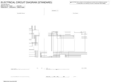
The Attached Diagram List

There are no reviews yet.