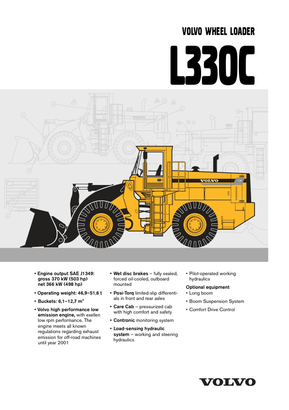
Volvo L330C Wheel Loader (Preview)
COVER
DESCRIPTIONS
(1) STANDARD PARTS, SERVICE
Electric welding
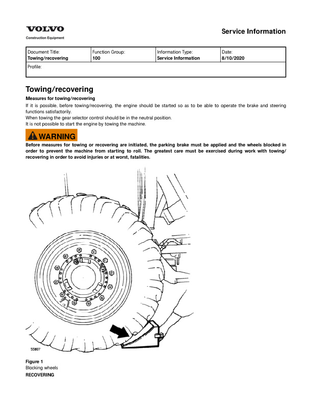
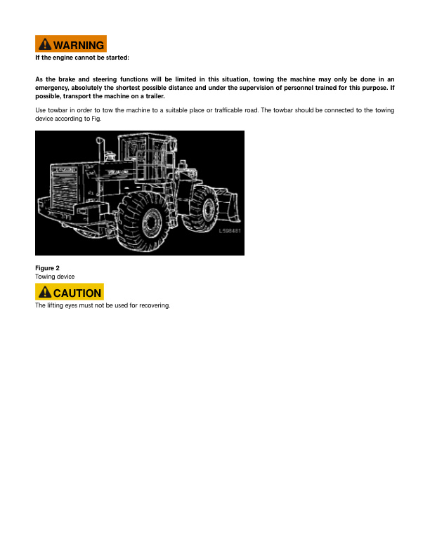
Towing recovering
Towing
(2) ENGINE WITH MOUNTING AND EQUIPMENT
Camshaft
Description (2)
Description (3)
Description
Engine timing gears
Injection timing device
Oil cooler
Pistons
(3) ELEC. SYSTEM; WARNING SYSTEM; INFORMATION SYSTEM; INSTRUMENTS
Charging batteries
Contronic System
Electrical distribution box in cab
Electrical distribution box
Functions which are not included in the central warning
General description
Instruments and controls
Monitored functions
Operating with the ECU disconnected, (electrical)
Other electrical functions
Service Contronic Display Unit
Special instructions when working on the electrical system
Units connected to the control unit
(4) POWER TRANSMISSION
Limited slip type differential
(5) BRAKE
Description (0
Description
Hydraulic diagram, brake system brake cooling circuit
Manual release of parking brake
(6) STEERING
Description
Lever steering, CDC (Comfort Drive Control)
Lever steering, description hydraulic system
Lever steering
Steering lever and ramp generator CU20, checking voltage in out
(7) FRAME; SPRINGS; DAMPING; AXLE SUSPENSION; WHEEL, TRACK UNIT
Frame joint
(8) MACHINERY HOUSE; CAB; EXTERIOR TRIM PARTS ANYWHERE
Description
(9) HYDRAULIC SYSTEM; DIGGING HANDLING GRADING EQUIPM; MISC. EQUIP
Boom kick-out and bucket positioner, adjusting
Boom kick-out and bucket positioner
Description
Detent function floating position and floating position
Detent function lifting boom kick-out (SW 18)
Functional diagram, working hydraulics, basic machine
Hydraulic diagram, working hydraulic
Hydraulic diagram, working hydraulics
DIAGRAMS
(3) ELEC. SYSTEM; WARNING SYSTEM; INFORMATION SYSTEM; INSTRUMENTS
Code key for connectors (connected to the circuit board)
Code key for connectors (other)
Code key for diodes
Codes used in wiring diagrams
Control unit, description of function
Explanations to wiring diagrams
List of circuits
Relay, description of function
Wiring diagram, 1 1 — 1 10
Wiring diagram, 2 1 — 2 9
Wiring diagram, 3 1 — 3 10
Wiring diagram, 4 1 — 4 10
Wiring diagram, 5 1 — 5 10
Wiring diagram, 6 1 — 6 10
Wiring diagram, 7 1 — 7 10
Wiring diagram, 8 1 — 8 9
Wiring diagram, 9 1 — 9 10
Wiring diagram, 10 1 — 10 8
Wiring diagram, 11 1 — 11 8
Wiring diagram, 12 1 — 12 10
Wiring diagram, 13 1 — 13 10
Wiring diagram, 14 1 — 14 10
Wiring diagram, 15 1 — 15 7
Wiring diagram, 16 1 — 16 5
Wiring diagram, 17 1 — 17 7
Wiring diagram, 18 1 — 18 8
Wiring diagram, 19 1 — 19 10 (2)
Wiring diagram, 19 1 — 19 10
Wiring diagram, 20 1 — 20 7
Wiring diagram, 21 1 — 21 9
(6) STEERING
Hydraulic diagram, steering system
INSTALLATION INSTRUCTIONS
CARETRACK
ENGINE HEATER
HIP BELT (2)
HIP BELT
INSTALLATION KIT FOR OPERATOR SEAT
KIT FOR FITTING THE RADIO
PROTECTING GRATING
ROTATING BEACON
SUN BLIND
WINDSHIELD WASHER
REPAIR
(0) GENERAL
Description
Drawings of tools (E-tools) which can be made in your own workshop
Product Identification Plates
Time Guide
(2) ENGINE WITH MOUNTING AND EQUIPMENT
Electrical key-turn engine stop, checking and adjusting
Oil sump gasket, changing
(4) POWER TRANSMISSION
Support bearing, reconditioning
(5) BRAKE
Brake discs, changing
Brake system retardation, checking function
Pressure in circuit, checking and adjusting
System pressure, checking and adjusting
(7) FRAME; SPRINGS; DAMPING; AXLE SUSPENSION; WHEEL, TRACK UNIT
Adjusting axial clearance in axle suspension
Changing bushings and seals in axle suspension
Measuring axial and radial clearance in axle suspension
(9) HYDRAULIC SYSTEM; DIGGING HANDLING GRADING EQUIPM; MISC. EQUIP
Cleanliness when working on hydraulic systems
Hydraulic diagram, complete
Specifications
SAFETY
(1) STANDARD PARTS, SERVICE
A few simple rules for batteries
A few simple rules of safety
A few simple rules when inflating tyres
A few simple rules when servicing
Charging batteries
Danger in connection with polymer materials
Measures to prevent fire
Refrigerant in air-conditioning units
Safety concerns everybody!
Service position
Starting with booster batteries
SPECIFICATIONS
(0) GENERAL
Brakes
Engine
Hydraulic system
Power transmission
Specifications
Steering sysem
Tightening torques
VOLVO BM standard tightening torques
(2) ENGINE WITH MOUNTING AND EQUIPMENT
Charge-air cooler (Intercooler)
Coolant filter
Cooling system (engine)
Cooling system
Cylinder block
Description (2)
Description (3)
Description of function, cooling fan
Description
Engine, checking function
Engine, fitting
Engine, removing
Fan pump motor, adjusting hydraulic pressure
Fan pump motor, checking hydraulic pressure
Fuel system, air bleeding
Fuel tank, changing
Idling speed, checking and adjusting
Injection angle (timing), adjusting
Injection angle (timing), checking
Injection pump
Injection timing device, checking
Injectors
Lubrication system
Radiator, changing
Sealing joint (cylinder head–cylinder block–cylinder liner)
Specifications (2)
Specifications (3)
Specifications (4)
Specifications (5)
Specifications (6)
Specifications (7)
Specifications (8)
Specifications (9)
Specifications (10)
Specifications (11)
Specifications (12)
Specifications (13)
Specifications (14)
Specifications (15)
Specifications (16)
Specifications
Stall speed, checking
Stop solenoid
(3) ELEC. SYSTEM; WARNING SYSTEM; INFORMATION SYSTEM; INSTRUMENTS
Specifications (2)
Specifications (3)
Specifications (4)
Specifications (5)
Specifications (6)
Specifications
(4) POWER TRANSMISSION
APS ll (Automatic Power Shift with Mode Selector)
Axles
Clutch discs 1st–2nd, changing in machine
Clutch discs, forward-reverse or 3rd– 4th, changing in machine
Clutch drum bearings, 1st or 2nd, changing in machine
Clutch drum bearings, forward, reverse, 3rd or 4th, changing in machine
Control valve, gear shifting
Description of function, torque converter transmission
Description
Differential carrier assembly, removing and fitting
Differential
Dual control, forward–reverse shifting
Gear shifting, signal to ECU from gear selector
Gear shifting, signal to in out from the ECU
Hub reduction gear, changing seals
Hub reduction gear, reconditioning
Hydraulic diagram, transmission
Monitoring brake cooling circuit filter and transmission filter
Rear axle, fitting
Rear axle, removing
Removing propeller shafts
Specifications (2)
Specifications (3)
Specifications (4)
Specifications (5)
Specifications (6)
Specifications (7)
Specifications (8)
Specifications
Torque converter and transmission
Torque converter, changing
Transmission, checking oil pressure
Transmission, fitting
Transmission, removing
Trimmer valve block
(5) BRAKE
Accumulator, changing seals
Accumulator, checking and adjusting
Brake accumulators, precharging pressure, checking
Brake disc wear, checking
Brake pump, changing
Parking brake, adjusting
Specifications (2)
Specifications (3)
Specifications (4)
Specifications (5)
Specifications
(6) STEERING
Control valve
Description
Flow amplifier, reconditioning
Flow amplifier
Function
Hydraulic oil pumps
Specifications (2)
Specifications (3)
Specifications
Steering cylinder, changing
Steering cylinder
Steering speed, lever steering, adjusting
Steering valve, ORBITROL
Steering valve, removed, reconditioning
Working pressure, checking and adjusting
(7) FRAME; SPRINGS; DAMPING; AXLE SUSPENSION; WHEEL, TRACK UNIT
Fitting removing extra counterweights
General description
Removing and fitting wheel
Specifications (2)
Specifications (3)
Specifications
Wheels and hubs
(8) MACHINERY HOUSE; CAB; EXTERIOR TRIM PARTS ANYWHERE
Air conditioning, performance test
Description
Electrical system, description of function
Fitting roll-over bar
Removing roll-over bar
Specifications (2)
Specifications (3)
Specifications (4)
Specifications (5)
Specifications
(9) HYDRAULIC SYSTEM; DIGGING HANDLING GRADING EQUIPM; MISC. EQUIP
3rd 4th function, checking and adjusting pressure
3rd 4th function
Accumulator, changing seals
Accumulator, checking and adjusting
Back-up valve, checking opening pressure
Boom suspension system, checking function
Boom Syspension System, BSS, for Wheel Loaders
Checking and adjusting shock pressure 3rd 4th function
Control valve functions
Hydraulic oil pump
Hydraulic oil pumps 1–4, balancing adjusting (Alt. 1)
Hydraulic oil pumps P1–P2 P3–P4, checking balance between pumps
Hydraulic oil pumps, balancing adjusting, maximum pressure
Hydraulic oil pumps, changing repairing
Hydraulic oil pumps, changing
Hydraulic oil tank, changing
Hydraulic system checking procedure Alt. 1
Leakage test
Lifting cylinder rear bushings, changing
Lifting cylinder, changing seals, in machine
Lifting cylinder, changing
Lifting cylinder, front bushing, changing
Lifting cylinder
Lifting frame
LS-signal for pumps 1–4, checking
Pressure-reducing valve R1 and R2, checking closing pressure
Safety valve TB, checking opening pressure
Separate attachment locking
Servo pressure, checking and adjusting
Servo pressure, checking at spool in control valve
Servo system
Servo valve, adjusting operating control
Shock and anti-cavitation functions
Shock valve, checking and adjusting, piston end of lifting cylinder
Shock valve, cheking and adjusting, tilting function
Specifications (2)
Specifications (3)
Specifications (4)
Specifications (5)
Specifications (6)
Specifications (7)
Specifications (8)
Specifications
Stand-by pressure, checking and adjusting (Alt. 2)
Tilting arm, changing bearing
Tilting cylinder, changing seals in machine
Tilting cylinder, changing
Tilting cylinder, front and rear bushings, changing
Tilting cylinder
Tilting link, changing
Tilting link, removed, changing bearing



There are no reviews yet.