ReadMeFirst
1 Printing single Pages, Chapters or the complete Manual
1.1 Printing single Pages or Chapters
1.2 Printing the complete Service Manual
2 Adding Comments
2.1 How to export your Comments
2.2 How to import Comments
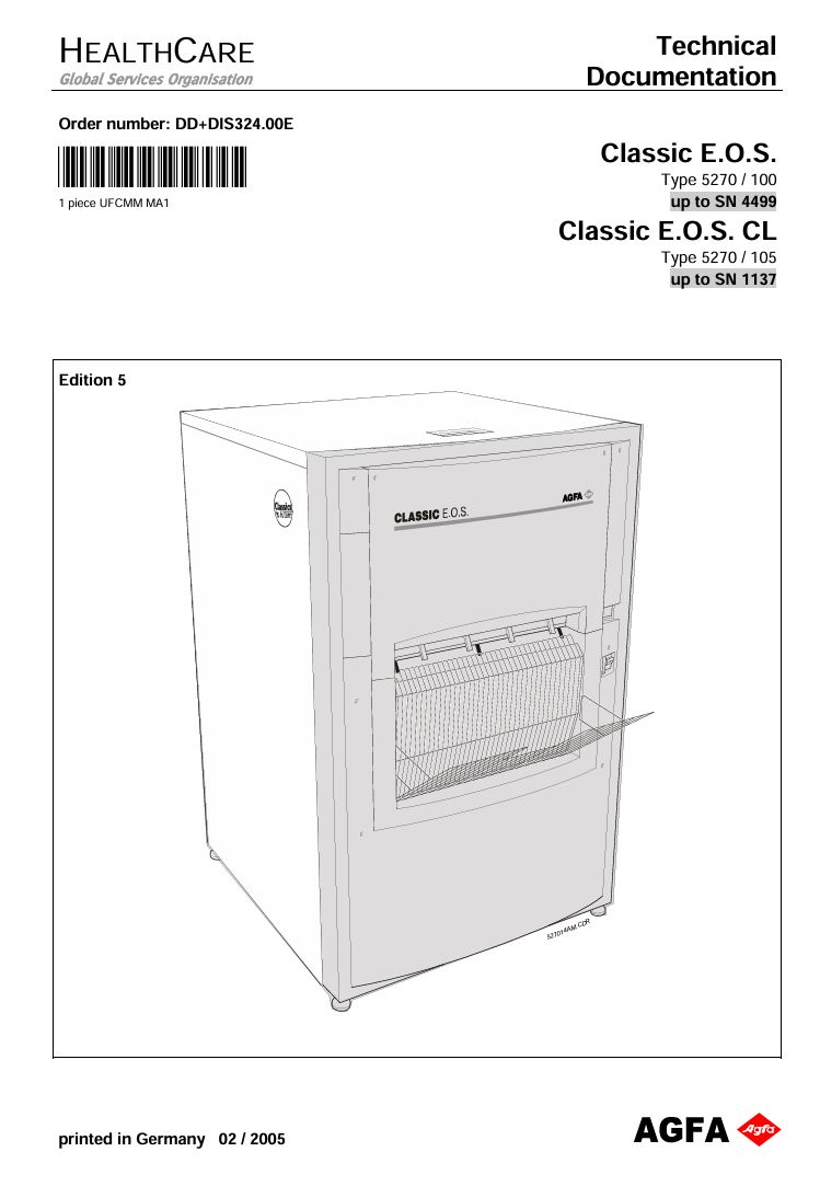
Chapter 00 – Frontpage
Chapter 00 – Order List for Documentation
Chapter 01 – Installation preparations – 5.3
1 Safety
2 Installation Preparations
2.1 Machine Transport
2.2 Checking the Shipment
2.3 Transport Check
2.4 Checking Safety Indicators on the Machine Box
2.5 Transport Path
2.6 Required Space at the Installation Site
2.6.1 Classic E.O.S. Type 5270/100
2.6.2 Classic E.O.S. CL Type 5270/105
2.7 Unpacking
2.8 Checking the Type Label
2.9 Checking the Accessory Box
3 Technical Data
3.1 Electrical Data
3.2 Ambient and Climatic Conditions
4 Dimensions and Weights
4.1 Classic E.O.S. Type 5270 / 100
4.2 Classic E.O.S. CL Type 5270/105
5 Machine Standards and Directives
Europe
USA
Canada
5.1 Radio Interference Suppression
Europe
5.2 Electromagnetic Compatibility
5.3 Certificates and Guidelines
Chapter 02 – Controls and connectors – 5.3
1 Control Panel
1.1 4-Key Control Panel
1.2 3-Key Control Panel
2 Switches
2.1 Machine Switches
2.2 Safety Switches
3 Installation Connections
3.1 Installation through the Front Panel (only for Classic E.O.S. Type 5270/100)
3.2 Installation through the Bottom
3.2.1 Classic E.O.S. (Type 5270/100)
3.2.2 Classic E.O.S. CL (Type 5270/105)
Chapter 03 – Installation and start-up – 5.3
1 Notes on the “Installation and Startup Procedures”
2 Installation
2.1 Slacken the Lock Nuts (Synchro-Drive)
3 Installation
3.1 Replacing the VDE Power Cable by the UL Power Cable
3.2 Supply / Disposal through Lower Front Panel (only Standalone Version Type 5270/100)
3.2.1 Instructions for breaking out the openings
3.2.2 Required openings for standard installations
3.2.3 Installing the exhaust connection
3.2.4 Installing supply hoses
3.2.5 Installing the disposal hoses
3.3 Supply and Disposal through the Machine Bottom
3.3.1 Hose connections
3.3.2 Installing the exhaust connection
3.3.3 Installing the replenisher hoses dev / fix and the water supply
3.3.4 Installing the disposal hoses
3.4 Connecting the Level Sensors
3.4.1 Replenisher tanks
3.4.2 Mixer
3.4.3 Waste tanks
3.5 Daylight / Darkroom Installation (only Stand-Alone Version Type 5270/100)
3.5.1 Machine in daylight, film feed in darkroom
3.5.2 Machine in darkroom, film output in the daylight
3.5.3 Light tight wall
4 Operation Startup (SN higher than 2200 and Type 5270/105)
4.1 Preparing the startup procedure
4.2 Adapting the mains supply
4.3 Filling the developer and fixer tanks
4.4 Switch on the Machine
4.4.1 Setting time and date in the “Service Settings” program
4.4.2 Resetting the service interval
4.4.3 Setting all options in the “Service Settings” program (Software Version MEOS 1201)
4.4.4 Calibrating the supply rates of developer and fixer pumps
4.4.5 Execute a Teach In
4.4.6 Overview of the program “Test & Adjust” (Software Version MEOS 1201)
4.4.7 Resetting infocounters
4.4.8 Important settings in the “Settings” program
4.4.9 Overview of the program “Info Counters” (Software Version MEOS 1201)
4.4.10 Overview of the user interface for the “Settings” program (Software Version MEOS 1201)
5 Operation Startup (SN up to 2200)
5.1 Adapting the mains supply
5.2 Filling the developer and fixer tanks
5.3 Switch on the Machine
5.4 Setup of process parameters
5.5 Calibration of the developer and fixer pumps
5.6 SETUP
5.6.1 Default
5.6.2 Service Program: SETUP (Software Version: CEOS1402)
5.7 Timer Setup
5.8 Reset INFO
6 Operation Start for all Machines with SNs up to 4500 or 1500 with 4-Key Control Panel and Software EOSUNIV1007
6.1 Preparing the startup procedure
6.2 Adapting the mains supply
6.3 Functional check of the GFI switch 0.FI
6.4 Filling the developer and fixer tanks
6.4.1 Manual filling (in Type 5270/100 and Type 5270/105)
6.4.2 Automatic filling with the AUTOFILL function (only in Type 5270/105)
6.5 Switching on the Machine
6.6 Calibrating the replenishment rate of developer and fixer upon first startup
6.7 Reset after switching on the machine
6.8 BASEINIT
6.8.1 Only execute a BASEINIT in case of:
6.8.2 Initiate a BASEINIT:
6.9 System Settings
6.9.1 Setting the software switches in the SERVICE program
6.9.2 Setting the process parameters on the control panel
6.9.3 Access to the SERVICE program
6.9.4 Setting date and time
6.9.5 Setting the service intervals in the SERVICE program
6.9.6 Executing a
6.9.7 Resetting the temporary infocounters in the SERVICE program
6.9.8 Display all
6.9.9 Setting the customer specific settings in the SERVICE program
6.9.10 DEFAULT settings ex factory / after BASEINIT
6.9.11 Processes
6.9.12 Process data
6.9.13 Application dependent process parameter
7 Operation Start for all Machines with SNs up to 4500 or 1500 with 3-Key Control Panel and Software EOSUNIV1007
7.1 Preparing the Startup Procedure
7.2 Adapting the mains supply
7.3 Functional Check of the GFI Switch 0.FI
7.4 Filling the Developer and Fixer Tanks
7.5 Switching on the Machine
7.6 Calibrating the Replenishment Rate of Developer and Fixer upon First Startup
7.7 Reset after Switching on the Machine
7.8 BASEINIT
7.9 System Settings
7.9.1 Setting the software switches in the SERVICE program
7.9.2 Setting the process parameters on the control panel
7.9.3 Access to the SERVICE program
7.9.4 Date and time
7.9.5 Resetting the service/maintenance intervals in the SERVICE program
7.9.6 Resetting the INFO in the SERVICE program
7.9.7 Setting the customer specific settings in the SERVICE program
7.9.8 Default settings ex factory / after BASEINIT
7.9.9 Processes
7.9.10 Process data
7.9.11 Application dependent process parameter
Chapter 04 – Intentionally left blank – 5.0
Chapter 05 – Functional Description – 5.0
1 Theory of function (up to SN 2200)
1.1 Film transport diagram
1.2 Switch-on phase
1.3 Filling phase
1.4 Heating phase
1.5 Standby phase
1.6 Emergency film phase
1.7 Film processing phase
1.8 Power failure
1.9 Data saving
2 Individual functions (up to SN 2200)
2.1 Dryer function
2.1.1 General
2.1.2 Dryer triggering
2.1.3 Dryer steps
2.1.4 Film cycle
2.1.5 Safety
2.2 Structure and function of the developer and fixer tank heaters
2.2.1 Structure of the developer heater
2.2.2 Structure of the fixer heater
2.2.3 Heating and control function of the developer heater
2.2.4 Heating and control function of the fixer heater
2.3 Water supply
2.4 Cooling system (Chiller)
2.5 Replenishment
2.5.1 Jog-cycle
2.6 Circulation of solutions
2.7 Drive motor
2.8 Exhaust
3 Roller diagram (up to SN 2200)
4 Functional data
5 Dryer setting (up to SN 2200)
5.1 Mains voltage ( 210 V (230 V *)
5.2 Mains voltage 190 V – 209 V (200 V *)
5.3 Mains voltage < 190 V (180 V *)
6 Theory of function (above SN 2200 and Type 5270/105)
6.1 Film transport diagram
6.1.1 Stand-alone Version Type 5270/100
6.1.2 CL Version Type 5270/105
6.2 Switch-on phase
6.3 Filling phase
6.4 Heating phase
6.5 Standby phase
6.6 Emergency film phase
6.7 Film processing phase
6.8 Power failure
6.9 Autodiagnosis
6.10 Data saving
7 Individual functions (above SN 2200 and Type 5270/105)
7.1 Dryer function
7.1.1 General
7.1.2 Dryer triggering
7.1.3 Dryer steps
7.1.4 Film cycle
7.1.5 Safety
7.1.6 Film transport check (only Type 5270/105)
7.2 Structure and function of the developer and fixer tank heaters
7.2.1 Structure of the developer heater
7.2.2 Structure of the fixer heater
7.2.3 Heating and control function of the developer heater
7.2.4 Heating and control function of the fixer heater
7.3 Water supply
7.4 Cooling system (Chiller)
7.5 Replenishment
7.5.1 Jog-Cycle
7.6 Circulation of solutions
7.7 Drive motor
7.8 Exhaust
7.9 Current sensor
7.10 AutoFill function (only Type 5270/105)
8 Roller diagram (above SN 2200 and Type 5270/105)
8.1 Stand-alone Version Type 5270/100
8.2 CL Version Type 5270/105
9 Functional data (above SN 2200 and Type 5270/105)
10 Dryer setting (above SN 2200 and Type 5270/105)
10.1 Mains voltage ( 210 V
10.2 Mains voltage 190 V – 209 V
10.3 Mains voltage < 190 V
Chapter 06 - Repair and Service - 5.3
Chapter 06.1 - Safety regulations and repair instructions - 5.3
1 Safety Check
2 Functional Check of the GFI Switch 0.FI
3 Repair Instructions
3.1 Cover Switch
3.2 Light Tightness of the Machine
3.3 Repairs on Circuits
3.4 Repairs on Printed Circuit Boards
3.5 Repairs on Printed Circuit Boards
3.6 Working on the Dryer
3.7 Handling of Chemicals
Chapter 06.2 - Tools and Auxiliary Equipment - 5.3
1 Recommended Tools and Auxiliary Equipment
2 Resetting Customer-Specific Settings (BASEINIT)
2.1 Range of Application
2.2 Function
2.3 Initiate a BASEINIT:
2.3.1 SERVICE program
2.3.2 Manual routine
2.3.3 Automatic routine
3 Resetting Counters and Lists (Infocounters)
3.1 Resetting the Temporary Infocounters
3.2 Resetting the Logbook, Error Lists, and Temporary Infocounters
3.3 Resetting the Operation Time Counter, Logbooks, Errors Lists, and Infocounters
3.3.1 Range of application
3.3.2 Function and activation
4 TEACH IN
4.1 Error Messages
4.2 Table of Current Values
Chapter 06.3 - Troubleshooting - 5.3
1 Operation Display
1.1 Status Displays
1.2 Displays During Heating and Filling Phase
2 Error Messages on the Display
2.1 Error Messages in Plaintext
2.2 Error Display with Service Numbers
3 Errors without Indication on the Display
3.1 Error Indication on the Synchro-Motor
3.2 Solution Heaters are Not Switched On
3.3 Faulty Dryer Triggering after Replacement of the Control Board GS1
3.4 High Wear and Tear on the Pump Bearings and Impeller Shafts
3.5 Failure of the Current Limitation Resistor R376 on the GS1
3.6 Failure of the Thermal Cutout for the Developer and Fixer Heater
3.7 Corrosion of Components on the Crossover Dryer Flap / Frame
3.8 Frequent Failures of the Control Board GS1 CM+952707830_ (F8.5270.7750)
4 Internal Error Diagnosis
4.1 Flow Chart
4.2 Error List for Internal Error Diagnosis
4.3 Activating the Internal Error Diagnosis via the Menu
4.3.1 Menu
4.3.2 Menu
4.4 Repair Instructions after Activating an Internal Error Diagnosis
Chapter 06.4 – Codes and Fuses – 5.3
1 Control Board GS1
Chapter 06.5 – Replacement of parts with adjustment instructions – 5.0
1 Removal and installation of the main drive (up to SN 2200)
1.1 Removing the lower horizontal shaft
1.2 Removing the vertical shaft
1.3 Removing the upper horizontal shaft
1.4 Installing the upper horizontal shaft
1.5 Installing the vertical shaft
1.6 Adjusting the bevel gears
1.7 Installing the lower horizontal shaft
2 Replacement of parts (up to SN 2200)
2.1 Main Board GS1
2.1.1 Individual steps of the replacement
2.2 Replacement of the clock chip (IC52)
2.3 Replacement of the device software (IC50 / IC51)
2.4 Replacement of the PLD (IC53), “programmed”
3 Setup and adjustments (up to SN 2200)
3.1 Calibrating the developer and fixer pump
4 Replacement of parts (above SN 2200 and Type 5270/105)
4.1 Main drive
4.1.1 Removing the lower horizontal shaft
4.1.2 Removing the vertical shaft
4.1.3 Removing the upper horizontal shaft
4.1.4 Installing the upper horizontal shaft
4.1.5 Installing the vertical shaft
4.1.6 Adjusting the bevel gears
4.1.7 Installing the lower horizontal shaft
4.2 Replacement of the Main Board GS1
4.2.1 Stand-alone Version Type 5270/100
4.2.2 CL Version Type 5270/105
4.2.3 Replacement of the clock chip (IC52)
4.2.4 Replacement of the device software EPROM (IC50 / IC51)
4.2.5 Replacement of the PLD (IC53), “programmed”
4.3 Replacement of the Current Sensor Board GS2
4.3.1 Stand-alone Version Type 5270/100
4.3.2 CL Version Type 5270/105
4.4 Replacement of the convection heater with thermal cut-out
4.5 Replacement of the infrared heater
4.6 Replacing the bracket of the infrared heater
5 Setup and adjustments (above SN 2200 and Type 5270/105)
5.1 Calibrating the supply rate for developer and fixer pump
5.2 Teach-in procedure
Chapter 06.6 – Adjustments for software and hardware – 5.3
1 Service Program “INPUT”: Software Version CEOS 1402 (SN up to 2200)
1.1 Information on “INPUT”
1.1.1 General Remark:
2 Service Program “OUTPUT”: Software Version CEOS 1402 (SN up to 2200)
2.1 Information on “OUTPUT”
2.1.1 General Remark:
3 Service Program “SETUP”: Software Version CEOS 1402 (SN up to 2200)
3.1 Information on “SETUP”
3.1.1 General Remark:
4 Service Program “MODULE”: Software Version CEOS 1402 (SN up to 2200)
4.1 Information on “MODULE”
4.1.1 General Remark:
5 Service Program “INFO”: Software Version CEOS 1402 (SN up to 2200)
5.1 Information on “INFO”
5.1.1 General Remark:
6 Overview of the “Service Settings” Program: Software Version MEOS 1201 (SN higher than 2200 and Type 5270/105)
7 Overview of the “Test & Adjust” Program: Software Version MEOS 1201 (SN higher than 2200 and Type 5270/105)
8 Overview of the “Info Counters” Program: Software Version MEOS 1201 (SN higher than 2200 and Type 5270/105)
9 Overview of the User Interface for the “Settings” Program: Software Version MEOS 1201 (SN higher than 2200 and Type 5270/105)
10 Overview of the User Interface for the “INPUT” Program: Software Version EOSUNIV1007 (3-Key Control Panel)
11 Overview of the User Interface for the “OUTPUT” Program: Software Version EOSUNIV1007 (3-Key Control Panel)
12 Overview of the User Interface for the “SETUP” Program: Software Version EOSUNIV1007 (3-Key Control Panel)
13 Overview of the User Interface for the “MODULE” Program: Software Version EOSUNIV1007 (3-Key Control Panel)
14 Overview of the User Interface for the “INFO” Program: Software Version EOSUNIV1007 (3-Key Control Panel)
15 Overview of the User Interface for the “Settings” Program: Software Version EOSUNIV1007 (4-Key Control Panel)
16 Overview of the User Interface for the “InfoCounter” Program: Software Version EOSUNIV1007 (4-Key Control Panel)
17 Overview of the User Interface for the “Test & Adjust” Program: Software Version EOSUNIV1007 (4-Key Control Panel)
18 Overview of the User Interface for the “Service Settings” Program: Software Version EOSUNIV1007 (4-Key Control Panel)
Chapter 06.7 – Software Versions – 5.7
Determining the Order Numbers of Control Board and Software
Introduction of Software Version CEOS 1117
Introduction of Software Version CEOS 1207
Introduction of Software Version CEOS 1303
Introduction of Software Version CEOS 1402
Introduction of Software Version CEOS 1501 and 1601
Introduction of Software Version CEOS 1714
Calibration of the developer and fixer replenishment rates
Automatic current check
Changing the Application
Switching off the buzzer signal
Remedy for Service 506
Remedy for Service 510 – crossflow fan turning
Surface replenishment (water) optimized
Introduction of Software Version CEOS 1801
Introduction of Software Version MEOS 1101
Introduction of Software Version MEOS 1201
Introduction of Software Version MEOS 1301
Introduction of Software Version MEOS 1401
Introduction of Software Version EOSUNIV1007
Control panel detection via current sensor
Calibration of the developer and fixer replenishment rates
EOSUNIV1007
Additional application
Implementation of an anti-algae water replenishment system
Additional infocounters to check the new pump calibration
Increased setting for replenishment rates in Curix/Mammo
Display texts for Software Version EOSUNIV1007 in 12 languages
3-Key Control Panel
4-Key Control Panel
Introduction of Software Version EOSU1102
Chapter 07 – Reference and Circuit Diagrams – 5.1
1 Abbreviations
2 Main Board GS1
2.1 Main Board GS1 (fuses, potentiometers, switches)
2.2 Main Board GS1 (LED)
2.3 Main Board GS1 (plugs, sockets)
3 Reference diagrams (up to SN 2200)
3.1 Machine front view
3.2 Machine side view, right hand side
3.3 Machine side view, left hand side
3.4 Machine top view
4 Current Sensor Board GS2 (above SN 2200 and Type 5270/105)
5 Reference diagrams (above SN 2200 and Type 5270/105)
5.1 Machine front view
5.1.1 Stand-alone Version Type 5270/100
5.1.2 CL Version Type 5270/105
5.2 Machine side view, right hand side
5.2.1 Stand-alone Version Type 5270/100
5.2.2 CL Version Type 5270/105
5.3 Machine side view, left hand side
5.3.1 Stand-alone Version Type 5270/100
5.3.2 CL Version Type 5270/105
5.4 Machine top view
5.4.1 Stand-alone Version Type 5270/100
5.4.2 CL Version Type 5270/105
6 Circuit diagrams
F1.5270.7005.0
F1.5272.7007.0
Chapter 08 – Spare Parts List – 6.4
SPARE PARTS LIST
DOCUMENT HISTORY
CONTENTS
EXTERNAL PANELS
FEED TABLE
DOCKING
HOSING TANK
HOSING COMPLETE
FRAME ELECTRONICS
ELECTRONIC PLATE
DRIVE
TANK PUMP DRIVE
TANK SUPPLY, DRAIN, SENSOR
TANK HEATER, CIRCULATION PUMP
EXHAUST
DRYER DRIVE
DRYER
DRYER FLAP
DRYER FAN
DEVELOPER RACK
DEVELOPER RACK DRIVE
FIXING RACK 1/2 / WATER RACK
FIXING RACK 1/2 / WATER RACK DRIVE
DISTRIBUTOR UNIT
ROLLER POSITIONING PLAN
LIGHT TIGHT COVER ACCESSORIE
SPARE PARTS KIT CATEGORIES
TYPE OVERVIEW
ACCESSORY OVERVIEW
Chapter 09 – Accessories – Installation Instructions for…
1 General
1.1 Introduction
1.2 Scope of delivery
1.3 Required tools and auxiliary equipment
1.4 Installation time
2 Installation instructions
2.1 Installation of the Classic E.O.S. CL
2.1.1 Installation preparations
2.1.2 Installation
2.1.3 Installing the chemical, water, and exhaust connections
2.1.4 Mains connection cable
2.1.5 Installing the control panel
2.2 Installation of the bottom plate for the Laser Imager
2.3 Modification measures on the Laser Imager
2.3.1 Installation of the steam gate
2.3.2 Changing the machine software
2.4 Connection of the Classic E.O.S. CL and the Laser Imager
3 Starting the machine
3.1 Staring the Classic E.O.S. CL
3.2 Starting the Laser Imager
Chapter 10 – Modifications – 5.0
Chapter 10 – Modifications – Installation Instructions for Grounding Strip Retrofitting Kit
1 Lieferumfang
2 Grund der Modifikation
3 Überprüfung
4 Einbau der Erdungsleiste
1 Scope of delivery
2 Reason for the modification
3 Checking
4 Installation of the grounding strip
1 Contenu de la livraison
2 Raison de la modification
3 Vérification
4 Pose de la goulotte de mise à la terre
Chapter 10 – Modifications – Installation Instructions for the Modification – angle rail
Lichteinfall in der Umlenkstrecke
Light leak in the crossover section
Interférence lumineuse dans la zone de renvoi
Incidência de luz no sistema de desvio
Chapter 11 – Technical Standard Modifications – 5.3
1 Introduction of Software Version CEOS 1117 (CM+9.5270.7757.0)
2 Introduction of Software Version CEOS 1207 (CM+9.5270.7758.0)
3 Introduction of Software Version CEOS 1303 (CM+9.5270.7759.0)
4 Introduction of Software Version CEOS 1402 (CM+9.5270.7760.0)
5 New Rubber Rollers in the Developer Rack (roller no. 14/CM+9.5210.8360.1)
6 New Exhaust Fan (CM+9.0431.7227.0)
7 New Circulation Pump (CM+9.5210.2660.4)
8 Ground Bus (F7.5270.4802.1)
9 Cover Bracket (CM+9.5270.3144.0)
10 Introduction of Software Version MEOS 1201 (CM+9527277600)
11 Introduction of Software Version MEOS 1301 (CM+9527290100)
12 Introduction of Software Version CEOS 1402 (CM+9527077600)
13 Introduction of a New Cross Flow Fan (CM+9043172370)
14 Introduction of a New Drive Motor with Gear (CM+9527015601)
15 Introduction of Improved Circulation Pumps in Developer, Fixer, and Water Tank (CM+9.5210.2620.0)
16 Introduction of Software Version MEOS 1401 (IC50 / IC51) (CM+9527290101)
17 Introduction of an Exhaust Duct Seal
18 Corrosion-Free Thermal Cutout for Developer and Fixer (CM+9042664520)
Chapter 12 – Maintenance Instructions – 5.4
Chapter 12 – Maintenance checklist
1 Maintenance Checklist (up to SN 2200)
2 Required tools / maintenance material (above SN 2200 and Type 5270/105)
2.1 Required special tools
2.2 Auxiliary means
2.3 Lubricants
2.4 Cleaning substances
2.5 Protection equipment
3 Cleaning suggestions (above SN 2200 and Type 5270/105)
3.1 General care (by the customer)
3.1.1 Stand-alone Version Type 5270/100
3.1.2 CL Version Type 5270/105
3.2 Periodical cleaning (by the Service Engineer)
4 Checking points, for visual check and functional check (above SN 2200 and Type 5270/105)
5 Maintenance Checklist (above SN 2200 and Type 5270/105)
Chapter 13 – Service Bulletins
SB01 – Software Versions CEOS 1601 – MEOS 1201
1 CEOS 1601
2 MEOS 1201
3 Machine specific application of the Software Versions CEOS and MEOS
SB02 – Introduction of the Cross Flow FanCM+9.0431.7237.0
SB03 – Introduction of the Software Version MEOS_1301
1 Solution for Service 506
2 Solution for Service 510 – Cross-flow fan turns
3 Signal processing for the combination of the Classic E.O.S. CL with the Thoramat
SB04 – Introduction of improved circulation pumpsin the developer, fixer, and water tank
SB05 – Introduction of Software CEOS_1714
1 MUST calibration of the developer and fixer replenisher pumps upon first startup after the installation of Software Version CEOS 1714 and higher
2 Switching the beeper off
3 Solution for Service 506
4 Solution for Service 510 – Cross-flow fan turns
5 Throughput-based replenishment (water) optimized
6 Modification of the application
6.1 Application specific settings / default settings
SB06 – Introduction of Software MEOS_1401…
1 Failure of the current limitation resistor R376
2 Remedy for Service 506
SB07 – Overview of Software Versions
1 Software Versions CEOS for Classic E.O.S. 5270 / 100 up through SN 2199
2 Software Version MEOS for Classic E.O.S. 5270 / 100 as of SN 2200 and Classic E.O.S. CL 5270/105 as of SN 1001
SB08 – Solution for frequent failures of theControl Board GS1 CM+9 5270 7830 _
SB09 – Measures against corrosion
SB10 – Introduction of Software EOSUNIV 1007…
1 Overview
2 New functions in “EOSUNIV 1007”
2.1 General:
2.2 MUST calibration
2.3 Display of the completed pump calibration
2.4 Anti-algae water replenishment
SB11 – obsolete
SB12 – Fehlermeldung bei der Durchführung des„Teach In“ nach Austausch derLeiterplatte GS1
SB13 – Introduction ofProcessor Software EOSU_1102Order Number: CM+9 5270 9350 4
SB14 – Introduction of theControl Board GS1incl. EOSU_1102 (Modification Kit)Order Number: CM+9 5270 7960 0
SB15 – Magnet Not Sufficiently Fixedin the Machine Cover
SB16 – Introduction of Anti-Algae-UnitType: 5279/100
SB17 – Installation of the Tank Reinforcement CM+9 5270 9071 0
SB18 – Failure of a Crossflow FanPreventive Measure to Avoid Failure of theFan 0M1
SB19 – Service 574:”IR heater in dryer defective”due to measuring error caused by wrongcable positioning at the CurrentSensor Board PCB2.
SB21 – New Option: Deactivating the Water Pump.
SB22 – Manufacturer’s Warning about Ground Fault Interrupters with Possibly Higher Trigger Current.
1 Introduction
2 Prerequisites
3 Checking the Function of the GFI Switch
SB23 – Empty Battery of the Clock Chip Causes…
1 Introduction
2 Prerequisites
3 Remedy
3.1 Replacing the Clock Chip
3.2 Setting the Data
3.2.1 Calibrating the Replenishment Rate for Type 5270/100/105 up to SN 2199
3.2.2 Calibrating the Replenishment Rate for Type 5270/100 as of SN 2200 up to SN 4499 and Type 5270/105 as of SN 1001 up to SN 1137
3.2.3 Setting Date and Time for Type 5270/100 up to SN 2199
3.2.4 Setting Date and Time for Type 5270/100 as of SN 2200 and Type 5270/105 as of SN 1001
3.3 Disposing of the Clock Chip
4 Checking the Remedy
4.1 Getting the Machine Ready for Operation
Chapter 14 – Installation Planning – 5.5
Chapter 15 – Intentionally left blank
Folder spine
Reviews
There are no reviews yet.