
Bobcat B15NS, B18NS, B20NSC DSB4536E00 (Preview)
DSB4536E00_2507_B15/18NS, B20NSC
– Foreword
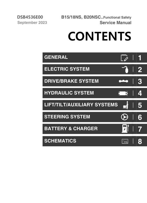
– Contents
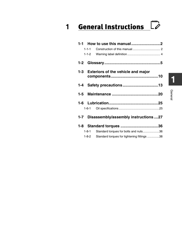
– 1 General Instructions
— 1-1 How to use this manual
— 1-1-1 Construction of this manual
— 1-1-2 Warning label definition
— 1-2 Glossary
— 1-3 Exteriors of the vehicle and major components
— 1-4 Safety precautions
— 1-5 Maintenance
— 1-6 Lubrication
— 1-6-1 Oil specifications
— 1-7 Disassembly/assembly instructions
— 1-8 Standard torques
— 1-8-1 Standard torques for bolts and nuts
— 1-8-2 Standard torques for tightening fittings
– 2 Electrical System
— 2-1 Overview
— 2-2 Lead Storage Battery
— 2-2-1
Exterior and specifications
— 2-2-2
Main Functions
— 2-2-3
Check
— 2-2-4
Maintenance
— 2-2-5
Removal and installation
— 2-3 Lithium Battery
— 2-3-1
Configuration of Lithium Battery in truck
— 2-3-2
Technical parameters
— 2-3-3
Description of charging port
— 2-3-4
Description of discharge port
— 2-3-5
Analysis and description of lithium battery failures
— 2-4 Emergency Switch
— 2-4-1
Exterior and specifications
— 2-4-2
How to use
— 2-4-3
Circuit configuration and main functions
— 2-5 Controller and related devices
— 2-5-1
Exterior and specifications
— 2-5-2
Circuit configuration and main functions
— 2-5-3
How to read the diagnostic CURTIS LED lights
— 2-5-4
Check
— 2-5-5
Removal and installation
— 2-6 Other loads
— 2-6-1
Fuse box
— 2-6-2
DC/DC converter
— 2-6-3
Lamp group
— 2-6-4
Horn
— 2-6-5
Communication protocol
— 2-7 Instrument Panel
— 2-7-1
Exterior and specifications
— 2-7-2
Names and functions
— 2-7-3
Battery capacity ratio
— 2-7-4
Fault Code
— 2-8 Programming Device for CURTIS HandheldDevice
— 2-8-1
Cautions for handling
— 2-8-2
Procedure for determining vehicle faults
— 2-8-3
Vehicle signal monitoring
— 2-8-4
CURTIS handheld device menus
— 2-9 Troubleshooting Fault Codes
— 2-9-1
Fault class
— 2-9-2
Curtis codes
— 2-9-3
How to Respond to Fault Codes
– 3 Drive/Brake System
— 3-1 Overview
— 3-2 Drive Motor
— 3-2-1 Exterior and specifications
— 3-2-2 How it works
— 3-3 Drive Axle
— 3-3-1 Exterior and specifications
— 3-3-2 How it works
— 3-3-3 Replacing drive gear oil
— 3-3-4 Drive wheel removal/installation
— 3-4 Accelerator
— 3-4-1 Exterior and specifications
— 3-4-2 How it works
— 3-4-3 Removal and installation
— 3-5 F/R Unit
— 3-5-1 Exterior and specifications
— 3-5-2 How it works
— 3-6 Service Brake System
— 3-6-1 Overview
— 3-6-2 Service brake pedal
— 3-6-3 Master cylinder
— 3-6-4 Service brake assembly
— 3-6-5 Instructions on removing and adjusting the brake
— 3-6-6 Adjusting the brake pedal
— 3-6-7 Maintenance and service
— 3-7 Parking brake system
— 3-7-1 Exterior and specification
— 3-7-2 How EM brake works
— 3-7-3 How Parking brake works electrically
— 3-7-4 Parking brake test
— 3-7-5 Manual release of parking brake
— 3-7-6 EM Parking brake removal/installation
— 3-8 Troubleshooting
— 3-8-1 Drive motor
— 3-8-2 Drive axle
— 3-8-3 Service brake
— 3-8-4 Parking brake
– 4 Hydraulic System
— 4-1 Overview
— 4-1-1 Components
— 4-1-2 Oil flow chart
— 4-2 Pump Motor
— 4-2-1 Exterior and specifications
— 4-2-2 How it works
— 4-2-3 Removal/installation of pump motor and main hydraulicpump
— 4-3 Control Valve
— 4-3-1 Exterior and specifications
— 4-3-2 How it works
— 4-4 Troubleshooting
— 4-4-1 Pump motor
— 4-4-2 Main hydraulic pump
– 5 Lift/Tilt/Mast Systems
— 5-1 Overview
— 5-1-1 Components
— 5-1-2 Oil flow
— 5-2 Control Valve
— 5-2-1 Exterior and specifications
— 5-2-2 How it works
— 5-2-3 Adjustment, removal and installation of lever and switchgroups
— 5-2-4 Control valve removal/installation
— 5-3 Mast Assembly
— 5-3-1 Exterior and specifications
— 5-3-2 How it works
— 5-3-3 Servicing the forks
— 5-3-4 Servicing chains
— 5-4 Troubleshooting
– 6 Steering System
— 6-1 Overview
— 6-1-1 Components
— 6-1-2 Oil flow chart
— 6-2 Steering control group
— 6-2-1 Exterior and specifications
— 6-2-2 How it works
— 6-2-3 Steering system air removal
— 6-2-4 Steering system pressure check
— 6-2-5 Removal/installation of steering wheel cover
— 6-2-6 Steering wheel removal/installation
— 6-2-7 Steering column removal/installation
— 6-3 Steering actuator group
— 6-3-1 Exterior and specifications
— 6-3-2 How it works
— 6-3-3 Rear wheel and hub removal/installation/adjustment
— 6-3-4 Steer axle removal/installation
— 6-3-5 Link assembly and steering cylinder removal/installation
— 6-4 Troubleshooting
– 7 Battery and Charger
— 7-1 Lithium Phosphate battery
— 7-1-1 Specifications
— 7-1-2 External view
— 7-1-3 Components exploded view
— 7-1-4 Charging gun socket interface
— 7-1-5 Battery schematic
— 7-1-6 Alarm default parameter table
— 7-1-7 BMS Parameter
— 7-1-8 Diagnostic tool
— 7-2 Charger for Lithium Phosphate battery
— 7-2-1 Overview
— 7-2-2 Technical parameters
— 7-2-3 Description of control panel
— 7-2-4 Charger maintenance
— 7-2-5 Troubleshooting
— 7-3 Lead battery
— 7-3-1 Specification
— 7-3-2 Major components
— 7-3-3 Precaution when use & installation
— 7-3-4 How to use
— 7-3-5 Regular maintenance
— 7-3-6 Disassembly and assembly
— 7-3-7 Fault list and troubleshooting
— 7-4 Lead charger
— 7-4-1 Exterior and specifications
— 7-4-2 How it works
— 7-4-3 Operation and use of charger
— 7-4-4 Troubleshooting method of charger
– 8 Schematics
— ● Hydraulic Schematic
— ● Electric Schematic 231233003002
– Revision History



Reviews
There are no reviews yet.