

Bobcat X231 Excavator 6722178 (6-12) (Preview)
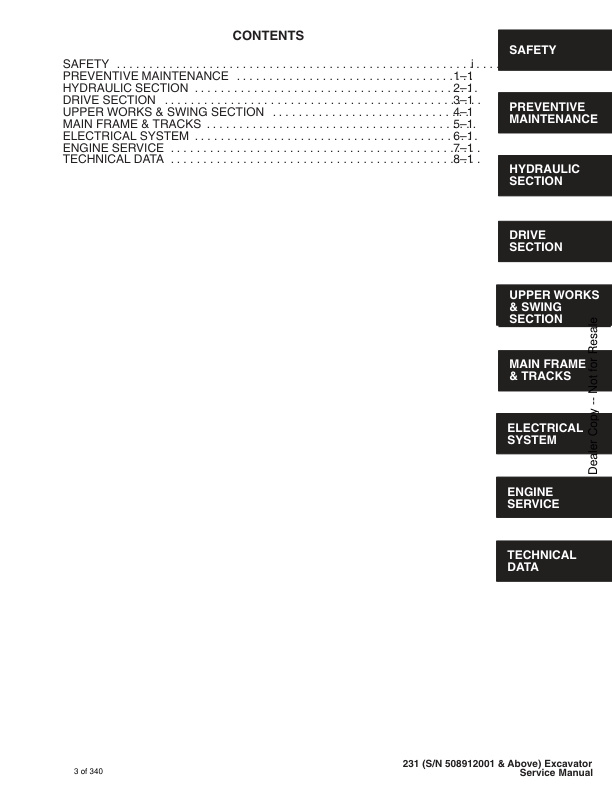
CONTENTS
– FOREWORD
– SAFETY
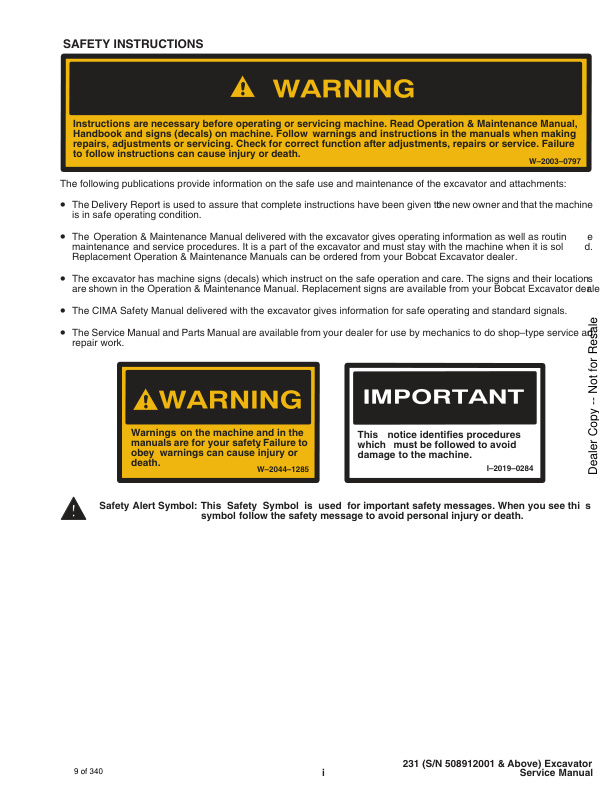
– SAFETY INSTRUCTIONS
– SERIAL NUMBER LOCATIONS
– HYDRAULIC EXCAVATOR SERIAL NUMBER
– ENGINE SERIAL NUMBER
– DELIVERY REPORT
– HYDRAULIC EXCAVATOR IDENTIFICATION
– MACHINE SIGNS TRANSLATIONS (DECALS)
PREVENTIVE MAINTENANCE
– SERVICE SCHEDULE
– ENGINE COVER
— Procedure
– AIR CLEANER SERVICE
— Replacing the Filter Element
– FUEL SYSTEM
— Fuel Specifications
— Fuel System Service
— Fuel Filters
— In–line Fuel Filter (If Equipped)
— Removing Air From The Fuel System
– ENGINE LUBRICATION SYSTEM
— Checking The Engine Oil
— Engine Oil and Filter Replacement
– COOLING SYSTEM
— Coolant Level
— Coolant Replacement
– HYDRAULIC SYSTEM
— Checking and Adding Fluid
— Replacement of the Hydraulic Filter
— Hydraulic Reservoir
— Diagnostic Couplers
– USING A BOOSTER BATTERY (JUMP STARTING)
— Procedure
– LUBRICATION OF THE HYDRAULIC EXCAVATOR
— Procedure
– FINAL DRIVE CASE
— Checking Oil Level
— Draining Final Drive Case
– HYDRAULIC SECTION
HYDRAULIC SECTION
– HYDRAULIC SCHEMATICS
– HYDRAULIC SERVICE INFORMATION
— Description
– MAIN RELIEF VALVES
— Checking the Relief Valve Pressure Settings
— Adjustment Procedure
— (With Dual Pressure Relief Valves) (S/N 508912381 & Above)
– HYDRAULIC PUMP FLOW TEST
– HYDRAULIC PUMP
— Removal And Installation
– HYDRAULIC PUMP
— Disassembly And Assembly
– HYDRAULIC CONTROL VALVE (Six Spool)
— Removal And Installation
— Parts Identification
— Disassembly And Assembly
– HYDRAULIC CONTROL VALVE (Three Spool)
— Removal And Installation
— Parts Identification
— Disassembly And Assembly
— Pressure Build–up Valve Adjustment Procedure
– PRESSURE REDUCING VALVE WITH ACCUMULATOR
— Removal And Installation
— Parts Identification
– ACCUMULATOR/VALVE
— Disassembly
— Assembly
— Setting The Safety Relief Valve
– ACCUMULATOR
— Charging
– AUXILIARY SELECTOR VALVE
— Removal And Installation
— Disassembly And Assembly
– TWO SPEED VALVE
— Removal And Installation
— Parts Identification
– PORT BLOCK
— Removal And Installation
– OIL COOLER
— Removal And Installation
– HYDRAULIC RESERVOIR AND FUEL RESERVOIR
— Removal And Installation
– HYDRAULIC FILTER ASSEMBLY
— Removal And Installation
– BOOM CYLINDER
— Removal And Installation
— Parts Identification
– ARM CYLINDER
— Removal And Installation
— Parts Identification
– BUCKET CYLINDER
— Removal And Installation
— Parts Identification
– BLADE CYLINDER
— Removal And Installation
— Parts Identification
– BOOM SWING CYLINDER
— Removal And Installation
— Parts Identification
– HYDRAULIC CYLINDER
— Disassembly
— Assembly
– JOYSTICK CONTROL CHANGE
DRIVE SECTION
– LEFT CONSOLE
— Lockout Valve Removal and Installation
— Cylinder Removal and Installation
— Removal and Installation
– LEFT JOYSTICK
— Removal and Installation
— Disassembly and Assembly
— Parts Identification
– RIGHT CONSOLE
— Removal and Installation
– RIGHT CONSOLE COVER
— Removal and Installation
– THROTTLE LEVER
— Low Idle Adjustment
— High Idle Adjustment
— Removal and Installation
– CONTROL CABLES
— Throttle Cable
— Blade Cable and Lever
– FOOT PEDAL AND STEERING LEVERS
— Removal and Installation
— Bushing Removal and Installation
– FINAL DRIVE
— Removal and Installation
— Parts Identification
– TRAVEL MOTOR
— Disassembly
— Assembly
UPPER WORKS AND SWING SECTION
– SWING MOTOR
— Removal and Installation
— Disassembly
— Assembly
– CROSS–OVER RELIEF VALVE
— Disassembly
— Assembly
– SWING MOTOR
— Parts Identification
– SWING GEAR BOX ASSEMBLY (WITH OR WITHOUT BRAKES)
— Disassembly
— Assembly
– UPPER WORKS AND SWING CIRCLE GEAR
— Removal and Installation
— Swing Bearing Removal
— Swing Bearing Installation
– CENTER SWIVEL JOINT
— Removal And Installation (through upper access removal)
— Removal And Installation (through bottom access cover)
— Parts Identification
MAIN FRAME AND TRACKS
– ENGINE COVER
— Removal and Installation
– SEAT AND MOUNTING FRAME
— Removal and Installation
– CENTER FLOOR PANEL
— Removal and Installation
– SWING MOTOR COVER
— Removal and Installation
– REAR FLOOR PANEL
— Removal and Installation
– INSPECTION COVER
— Removal and Installation
– TOOL BOX
— Removal and Installation
– BUCKET
— Removal and Installation
– ARM
— Removal and Installation
– BOOM
— Removal and Installation
– BOOM SWING BRACKET
— Removal and Installation
– WORK GROUP HOSE INSTALLATION
— Hose Mounting and Dimensions
– BLADE
— Removal and Installation
– TRACK
— Track Tension Adjustment
— Rubber Tracks
— Steel Tracks
— Removal and Installation (Rubber Track)
— Removal and Installation (Steel Track)
– TRACK FRAME
— Disassembly and Assembly
– TRACK IDLER
— Parts Identification
— Disassembly
— Assembly
— Disassembly and Assembly
– TRACK ROLLER
— Parts Identification
— Disassembly
— Assembly
– ROPS
— Removal and Installation
— Front Window Removal
— Side Window Removal
ELECTRICAL SYSTEM
– ELECTRICAL CHARTS
– TROUBLESHOOTING
– ELECTRICAL SYSTEM
— Description
— Fuses
— Electrical System Service
– BATTERY
— Checking the Battery
— Removal and Installation
– ALTERNATOR
— Belt Adjustment
— Removal And Installation
– STARTER
— Removal and Installation
— Disassembly and Assembly
— Cleaning and Inspection
– FUEL LEVEL SENDER
— Removal and Installation
— Checking
– INSTRUMENT PANEL
— Removal And Installation
– HOURMETER
— Removal And Installation
– WIPER MOTOR AND SWITCH
ENGINE SYSTEM
– TROUBLESHOOTING
– VALVE CLEARANCE
— Adjustment
– ENGINE COMPRESSION
— Checking
– FUEL SYSTEM
— Fuel Filters
— Fuel Filter Assembly
— In–Line Fuel Filter (if equipped)
— Removing Air From the Fuel System
– FUEL SHUT–OFF SOLENOID
— Adjustment
— Removal and Installation
– FUEL INJECTION PUMP
— Checking the Injection Pump
— Removal and Installation
— Timing the Injection Pump
– FUEL INJECTOR NOZZLES
— Checking the Injector Nozzle
– GLOW PLUGS
— Removal and Installation
— Checking the Glow Plug
– RADIATOR
— Removal and Installation
– AIR CLEANER
— Removal and Installation
– MUFFLER
— Removal and Installation
– HEATER
— Removal and Installation
– ENGINE
— Removal and Installation
– ENGINE FLYWHEEL
— Removal and Installation
— Flywheel Ring Gear
– CYLINDER HEAD
— Removal
— Disassembly
— Servicing the Cylinder Head
— Assembly
— Installation
– ENGINE REPAIR
— Removing the Gearcase
— Removing the Timing Gear, Camshaft and Oil Pump
— Removing the Pistons and Crankshaft
— Servicing the Timing Gear and Camshaft
— Servicing the Connecting Rods and Pistons
— Servicing the Crankshaft
— Servicing the Cylinder Liners
— Lubrication System
— Oil Pump Service
— Water Pump Service
– ENGINE ASSEMBLY
— Installing the Crankshaft
— Installing the Pistons
— Installing the Gearcase
TECHNICAL DATA
– HYDRAULIC EXCAVATOR SPECIFICATIONS
— Machine Dimensions
— Lifting Capacity With Blade Off Ground (Model 231 with Canopy)
— Lifting Capacity With Blade Off Ground (Model 231 with Cab)
— Engine
— Hydraulic System
— Swing System
— Hydraulic Cylinders
— Drive System
— Brakes
— Undercarriage
— Track
— Capacities
— Miscellaneous
— Fuel Injection Nozzles
— Fuel Injection Pump
— Cylinder Head
— Valves
— Valve Springs
— Rocker Arms
— Camshaft
— Cylinder
— Piston Rings
— Pistons
— Crankshaft
— Oil Pump
— Engine Oil Specifications
– ENGINE BOLT TORQUE
— Re–Grinding The Crankshaft
– FUEL, COOLANT AND LUBRICANTS
– OIL SPECIFICATIONS
— Description
SERVICE MANUAL REVISON
– 231-1
– 231-2
– 231-3
– 231-4
– 231-5
– 231-6
– 231-7
– 231-8


Reviews
There are no reviews yet.