

Bobcat X320 Excavator 6722642 (6-12) (Preview)
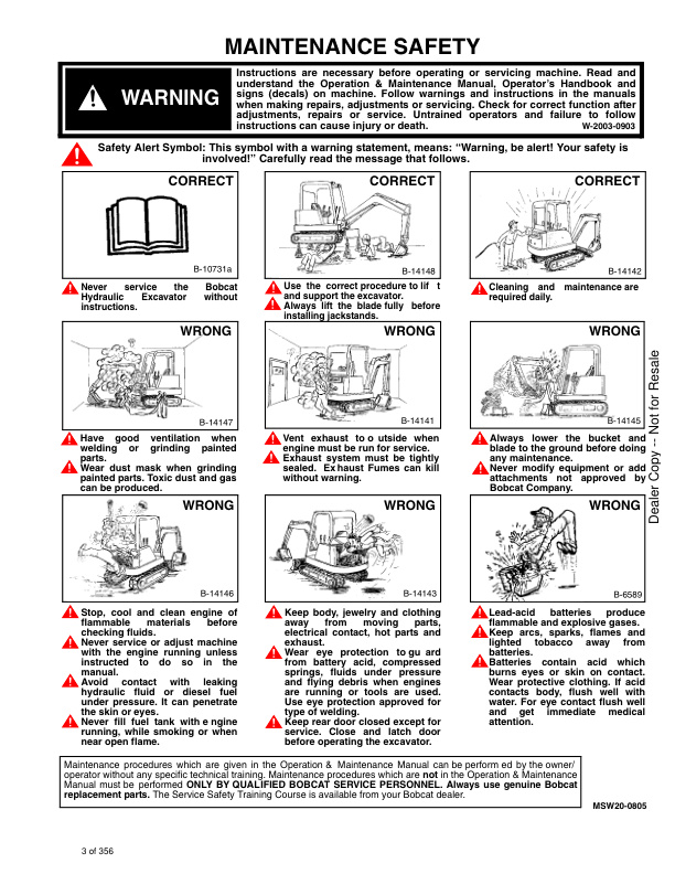
MAINTENANCE SAFETY
CONTENTS
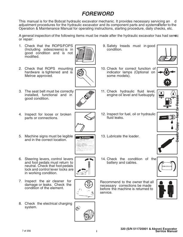
– FOREWORD
– SAFETY INSTRUCTIONS
– SERIAL NUMBER LOCATIONS
– HYDRAULIC EXCAVATOR SERIAL NUMBER
– ENGINE SERIAL NUMBER
– DELIVERY REPORT
– HYDRAULIC EXCAVATOR IDENTIFICATION
PREVENTIVE MAINTENANCE
– SERVICE SCHEDULE
– ENGINE COVER
— Opening the Cover
– AIR CLEANER SERVICE
– FUEL SYSTEM
— Fuel System Service
— Maintenance
— Fuel Filter
– ENGINE LUBRICATION SYSTEM
— Engine Oil and Filter Replacement
– COOLING SYSTEM
— Coolant Level
— Coolant Replacement
– HYDRAULIC SYSTEM
— Checking and Add Fluid
— Diagnostic Couplers
— Replacement of the Hydraulic Filter
— Hydraulic Reservoir
— Replacement of the Hydraulic Fluid
– USING A BOOSTER BATTERY (JUMP STARTING)
— Procedure
– LUBRICATION OF THE HYDRAULIC EXCAVATOR
— Procedure
HYDRAULIC SECTION
– HYDRAULIC SCHEMATICS
– HYDRAULIC SYSTEM TROUBLESHOOTING
– HYDRAULIC SERVICE INFORMATION
— Checking the Main Relief Valves
— Checking the Hydraulic Pump
– HYDRAULIC PUMP
— Disassembly
— Assembly
– HYDRAULIC CONTROL VALVE (6–Spool) DUKES VALVE (S/N 511720001–511721411)
— Removal And Installation
— Parts Identification
— Disassembly
— Inlet Section (R.H. and L.H. Travel)
— Disassembly
— Assembly
— Valve Sections (Boom, Bucket & Arm)
— Disassembly
— Assembly
— Valve Sections (Auxiliary)
— Disassembly
— Assembly
— Assembly
— Port Relief Valve
— Disassembly
— Assembly
— Adjustment
— Main Relief Valve
— Disassembly
— Assembly
— Adjustment
– HYDRAULIC CONTROL VALVE (3–Spool) DUKESVALVE (S/N 511720001–511721411)
— Removal And Installation
— Parts Identification
— Disassembly
— Inlet Section (Housing Swing)
— Disassembly
— Assembly
— End Cover (Boom Swing) and Valve Section (Blade)
— Disassembly
— Assembly
— Load Check Block
— Disassembly
— Assembly
— Build–Up Valve
— Assembly
— Main Relief Valve
— Disassembly
— Assembly
— Adjustment
– HYDRAULIC CONTROL VALVE (6–Spool) HUSCO VALVE(S/N 511721412 & Above)
— Parts Identification
— Disassembly
— Inlet Section Disassembly And Assembly
— Right Hand & Left Hand Travel Section
— Disassembly
— Assembly
— Boom, Bucket & Arm Section
— Disassembly
— Assembly
— Auxiliary Section
— Disassembly
— Assembly
– PORT RELIEF VALVES HUSCO VALVE
— Parts Identification
— Port Relief Valve Pressure Setting
— Disassembly
— Assembly
— Adjustment
– MAIN RELIEF VALVES HUSCO VALVE
— Parts Identification
— Disassembly
— Assembly
— Adjusting The Main Relief Valves
– HYDRAULIC CONTROL VALVE (3–Spool) HUSCO VALVE (S/N 511721412 & Above)
— Parts Identification
— Disassembly
— Blade And Boom Swing Section
— Disassembly
— Assembly
— Lockout Valve Assembly
— Disassembly
— Lockout Valve Assembly
— Swing Motor Valve Section
— Disassembly
— Assembly
— Build–Up Valve Disassembly
— Build Up Valve Assembly
— Build Up Valve Test Procedure
– BOOM CYLINDER
— Removal And Installation
— Boom Shield
— Boom Cylinder
– ARM CYLINDER
— Removal And Installation
– BUCKET CYLINDER
— Removal And Installation
– BLADE CYLINDER
— Removal And Installation
– BOOM SWING CYLINDER
— Removal And Installation
– HYDRAULIC CYLINDER
— Disassembly
— Assembly
— Disassembly
— Assembly
– HYDRAULIC FILTER ASSEMBLY
— Removal And Installation
– AUXILIARY COUPLERS
— Removal And Installation
– JOYSTICK MANIFOLD WITH ACCUMULATOR
— Removal And Installation
— Disassembly And Assembly
– DRAIN BLOCK
— Filter Screen
— Removal And Installation
– OIL COOLER
— Removal And Installation
– JOYSTICK CONTROL CHANGE
DRIVE SECTION
– FLOORMAT AND FLOOR PANELS
— Removal and Installation
– LEFT CONTROL CONSOLE
— Microswitch Adjustment Procedure
— Lockout Microswitch Removal and Installation
— Console Cover Removal and Installation
— Joystick Removal and Installation
— Removal and Installation
– FUEL TANK
— Removal and Installation
– LOCK LEVER
— Left Hand Removal and Installation
— Adjustment Procedure
– LATCH HOOK
— Left Hand Removal and Installation
– GAS SPRING
— Left Hand Removal and Installation
– UPPER CONSOLE
— Left Hand Removal and Installation
– RIGHT CONTROL CONSOLE
— ROPS Canopy Models
— Cab Models
— Console Cover Removal and Installation
— Joystick Removal and Installation
— Control Console Removal and Installation
— Hydraulic Tank Removal and Installation
– TRAVEL LEVERS
— Removal and Installation
– RIGHT HAND PEDAL (Boom Swing)
— Removal and Installation
– LEFT HAND PEDAL (Auxiliary)
— Removal and Installation
– ROCKERSHAFT
— Removal and Installation
– LINKAGE RODS
— Removal and Installation
– BLADE LEVER
— Removal and Installation
– FINAL DRIVE
— Removal and Installation
– DRIVE MOTOR ASSEMBLY (Kayaba) (S/N 511720001 – 23974)
— Parts Identification
— Disassembly
— Assembly
— Checking Oil Level
— Draining Final Drive Case
– DRIVE MOTOR (SOM) (S/N 23975 & Above)
— Parts Identification
— Disassembly
— Assembly
— Checking Oil Level (S/N 23975 & Above)
– JOYSTICK
— Parts Identification
— Disassembly and Assembly
UPPER WORKS AND SWING SECTION
– SWING MOTOR
— Testing the Cross Ports Reliefs
— Start the Engine
— Removing the Cross Port Reliefs
— Removal and Installation
— Disassembly
— Assembly
— Motor Timing
– CROSS PORT RELIEF VALVE
— Disassembly
— Assembly
— Description
– UPPERSTRUCTURE
— Removal
— Installation
– CENTER SWIVEL JOINT
— Removal And Installation
— Disassembly and Assembly
– SWING CIRCLE GEAR
— Removal And Installation
– ROPS CANOPY
— Removal And Installation
– CAB
— Removal And Installation
— Door (Removal And Installation)
— Front Window (Removal And Installation)
— Front Lower Glass (Removal And Installation)
— Front Upper Plexiglass (Removal And Installation)
— Door Glass (Removal And Installation)
— Left Hand Side Glass (Removal And Installation)
— Rear Glass (Removal And Installation)
— Right Hand Side Glass (Removal And Installation)
– CAB/CANOPY REAR COVER
— Removal
— Installation
– AIR BAFFLE (Cab Models Only)
— Removal And Installation
– BELLY PAN (Field Installed)
— Removal And Installation
MAIN FRAME AND TRACKS
– ENGINE COVER
— Removal and Installation
– REAR CORNER POSTS
— Removal and Installation
– SEAT AND SEAT MOUNT
— Removal and Installation
– SPEED CONTROL LEVER/SWING LOCK LEVER AND MOUNTING
— Removal and Installation
– BUCKET
— Removal and Installation
— Installation
– ARM
— Removal and Installation
– BOOM
— Removal and Installation
– SWING POST
— Removal And Installation
— Bushing Replacement
— Swing Post Bushing Removal
— Bushing Installation
– TRACK
— Track Tension Adjustment
— Removal and Installation
— Damage Identification and Causes
– TRACK FRAME
— Disassembly and Assembly
– TRACK IDLER
— Parts Identification
— Disassembly
— Assembly
– TRACK ROLLER
— Parts Identification
— Disassembly
— Assembly
– TRACK
— Damage Identification and Causes
ELECTRICAL SYSTEM
– ELECTRICAL SCHEMATIC
– TROUBLESHOOTING
– ELECTRICAL SYSTEM
— Description
— Fuses
— Electrical System Service
– BATTERY
— Checking the Battery
— Removal and Installation
– BATTERY BOX
— Removal and Installation
– CAB ELECTRICAL (Cab Option)
– ALTERNATOR
— Checking the Alternator Output
— Belt Adjustment
— Electrical Connection
— Removal and Installation
— Check the Alternator Output
— Alternator Output Test
— Alternator Regulator Test
— Disassembly and Assembly
— Stator Continuity Test
— Stator Ground Test
— Rotor Continuity Test
— Rotor Ground Test
— Rectifier Continuity (Diode) Test
— Disassembly and Assembly (New Style)
– STARTER
— Removal and Installation
— Disassembly and Assembly
— Cleaning and Inspection
– HORN
— Removal and Installation
– FUEL LEVEL SENDER
— Removal and Installation
ENGINE SERVICE
– TROUBLESHOOTING
– VALVE CLEARANCE
— Adjustment
– ENGINE COMPRESSION
— Checking
– FUEL FILTER
— Element
— Removing Air from the Fuel System
— Removal and Installation
– FUEL INJECTION PUMP
— Checking the Injection Pump
— Removal and Installation
— Timing the Injection Pump
– FUEL INJECTOR NOZZLES
— Checking the Injector Nozzle
– GLOW PLUGS
— Removal and Installation
— Checking the Glow Plug
– ENGINE
— Removal and Installation
– SPARK ARRESTOR MUFFLER
– RADIATOR
— Checking the Radiator and Radiator Cap
— Removal and Installation
— Hydraulic Pump Coupler
– CYLINDER HEAD
— Removal of the Cylinder Head
— Disassembly of the Cylinder Head
— Servicing the Cylinder Head and Valves
— Checking Valve Springs
— Checking Rocker Arm and Shaft
— Installing the Cylinder Head
– TIMING GEAR COVER
— Removal and Installation
– TIMING GEAR, CAMSHAFT AND OIL PUMP
— Removal and Installation
— Oil Pump Service
— Servicing the Camshaft
– CRANKSHAFT AND PISTONS
— Removal and Installation
— Crankshaft Service
— Servicing the Connecting Rods and Pistons
– CYLINDER LINERS
— Checking the Cylinder Liners
— Cylinder Liner Installation
– WATER PUMP
— Removal and Installation
— Disassembly and Assembly
SPECIFICATIONS
– HYDRAULIC EXCAVATOR SPECIFICATIONS
— Machine Dimensions
— Lifting Capacity
— SPECIFICATIONS
– ENGINE SPECIFICATIONS
— Engine
— Fuel Injector Nozzles
— Fuel Injection Pump
— Cylinder Head
— Valves
— Valve Springs
— Rocker Arms
— Camshaft
— Cylinders
— Piston Rings
— Pistons
— Crankshaft
— Oil Pump
— Thermostat
— Engine Torque
— Crankshaft Re–Grind Data
– FUEL, COOLANT AND LUBRICANTS
– OIL SPECIFICATIONS
– BUCKET SPECIFICATIONS
SERVICE MANUAL REVISON
– 320-1
– 320-2
– 320-3
– 320-4
– 320-5





Reviews
There are no reviews yet.