
Bobcat X325, X328 Excavator 6900462 (6-12) (Preview)
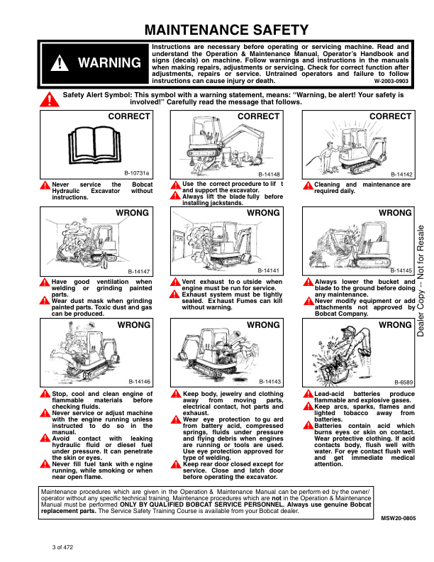
MAINTENANCE SAFETY
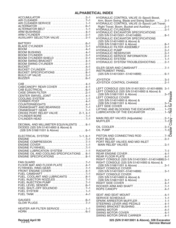
ALPHABETICAL INDEX
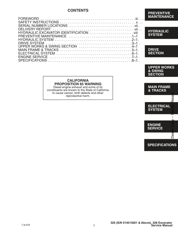
CONTENTS
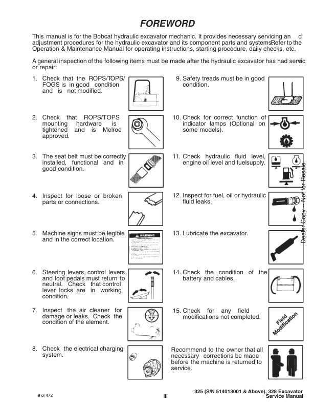
– FOREWORD
– SAFETY INSTRUCTIONS
– SERIAL NUMBER LOCATIONS
– HYDRAULIC EXCAVATOR SERIAL NUMBER
– ENGINE SERIAL NUMBER
– DELIVERY REPORT
– HYDRAULIC EXCAVATOR IDENTIFICATION
PREVENTIVE MAINTENANCE
– SERVICE SCHEDULE
– LIFTING AND BLOCKING THE EXCAVATOR
— Procedure
– TRANSPORTING THE HYDRAULIC EXCAVATOR
– ENGINE COVER
— Opening The Engine Cover
— Adjustment Of The Engine Cover Latch
– AIR CLEANER SERVICE
— Replacing The Filter Element (325 S/N 514013001–514014899)
— Replacing The Filter Element (325 S/N 514014900 &Above) & (328 S/N 516611001 & Above)
– FUEL SYSTEM
— Fuel Specifications
— Filling The Fuel Tank
— Fuel System Maintenance
— Fuel Filter (325 S/N 514013001–514014899)
— Fuel Filter (325 S/N 514014900 & Above) & (328 S/N516611001 & Above)
— Removing Air From The Fuel System (325 S/N514013001–514014899)
– ENGINE LUBRICATION SYSTEM
— Checking Engine Oil
— Replacement Of Oil And Filter
– COOLING SYSTEM
— Coolant Level
— Coolant Replacement
– ALTERNATOR BELT
— Adjustment
– ELECTRICAL SYSTEM
— Using A Booster Battery (Jump Starting)
– HYDRAULIC SYSTEM
— Checking And Adding Fluid
— Replacing The Hydraulic Oil
— Replacing The Hydraulic Filter
— Replacing The Drain Line Filter
– SPARK ARRESTOR MUFFLER (325 S/N 514014900 &Above) & (328 S/N 516611001 & Above)
— Cleaning The Spark Arrestor Muffler
– SPARK ARRESTOR MUFFLER (325 S/N 514013001–514014899)
— Cleaning The Spark Arrestor Muffler
– TRAVEL MOTOR
— Checking The Oil Level
— Draining And Refilling
– LUBRICATION OF THE HYDRAULIC EXCAVATOR
– HEATER AIR FILTER (With Cab Option Only) (325 S/N514013001–514014899)
– HEATER AIR FILTER (With Cab Option Only) (325 S/N514014900 & Above) & (328 S/N 516611001 & Above)
HYDRAULIC SECTION
– HYDRAULIC SCHEMATICS
– HYDRAULIC SYSTEM TROUBLESHOOTING
– HYDRAULIC SERVICE INFORMATION
— Description
— Checking The Main Relief Valves
— Testing The Swing Circuit Relief Valve
— Testing The Auxiliary And Bucket Circuit Relief Valve
— Testing The Left Hand Travel Circuit Relief Valve
— Testing The Right Hand Travel Circuit Relief Valve
— Testing The Boom Circuit Relief Valve
– CROSS PORT RELIEF VALVE
— Description
— Testing
– HYDRAULIC PUMP
— Checking the Hydraulic Pump
— Removal And Installation (325 S/N 514013001–514014899)
— Parts Identification (325 S/N 514013001– 514014899)
— Removal And Installation (325 S/N 514014900 &Above) & (328 S/N 516611001 & Above)
— Disassembly (325 S/N 514013001–514014899)
— Assembly (325 S/N 514013001–514014899)
– HYDRAULIC CONTROL VALVE (5–Spool)
— Left Travel, Right Travel, Boom, Bucket and Auxiliary
— Description
— Removal And Installation (325 S/N 514013001–514014899)
— Removal And Installation (325 S/N 514014900 &Above) & (328 S/N 516611001 & Above)
— Left Travel, Right Travel, Boom, Bucket and Auxiliary
— Parts Identification
— Disassembly
— Outlet Sections Disassembly
— Mid Inlet Section Disassembly
— Mid Inlet Section Assembly
— Left Travel, Right Travel and Auxiliary Disassembly
— Left Travel, Right Travel and Auxiliary Assembly
— Boom And Bucket Disassembly
— Boom And Bucket Assembly
— Assembly
– PORT RELIEF VALVES AND MID INLET MAIN RELIEF VALVES
— Parts Identification
— Port Relief Valve Pressure Setting
— Disassembly
— Assembly
– MAIN RELIEF VALVES (Adjustable)
— Parts Identification
— Pressure Settings
— Disassembly
— Assembly
— Adjusting The Main Relief Valves
– HYDRAULIC CONTROL VALVE (5–Spool)
— Boost, Arm, Boom Swing, Blade And Swing Section
— Description
— Removal And Installation
— Parts Identification
— Disassembly
— Inlet Section Disassembly
— Inlet Section Assembly
— Arm, Boost And Swing Motor Disassembly
— Arm, Boost And Swing Motor Assembly
— Boom Swing Disassembly
— Boom Swing Assembly
— Blade Disassembly
— Blade Assembly
— Assembly
– ACCUMULATOR
— Removal And Installation
— Parts Identification (S/N 514013001 – 514017331& 516611001 – 516611918)
— Disassembly (S/N 514013001 – 514017331& 516611001 – 516611918)
— Assembly
— Parts Identification (S/N 514017312 & Above &516611919 & Above)
— Disassembly (S/N 514017312 & Above &516611919 & Above)
— Assembly (S/N 514017312 & Above &516611919 & Above)
— Testing (All Models)
– PORT BLOCK
— Removal And Installation
– BUILD UP VALVE
— Description
— Removal And Installation
— Disassembly And Assembly
– AUXILIARY SELECTOR VALVE
— Removal And Installation (325 S/N 514013001–514014899)
— Removal And Installation (325 S/N 514014900 &Above) & (328 S/N 516611001 & Above)
— Disassembly And Assembly
– OIL COOLER
— Removal And Installation
– HYDRAULIC RESERVOIR
— Removal And Installation
– HYDRAULIC FILTER ASSEMBLY
— Removal And Installation
– CASE DRAIN FILTER
– BOOM CYLINDER SHIELD
— Removal And Installation
– BOOM CYLINDER
— Removal And Installation
– BOOM CYLINDER
— Parts Identification
– ARM CYLINDER
— Removal And Installation
— Parts Identification
– BUCKET CYLINDER
— Removal And Installation
— Parts Identification
– BLADE CYLINDER
— Removal And Installation
— Parts Identification
– BOOM SWING CYLINDER
— Removal And Installation
— Parts Identification
– HYDRAULIC CYLINDER
— Disassembly
— Assembly
– JOYSTICK CONTROL CHANGE
— ISO to STANDARD Control Pattern
— STANDARD To ISO Control Pattern
DRIVE SECTION
– RIGHT CONSOLE COVER (325 S/N 514013001–514014899)
— Removal And Installation
– RIGHT CONSOLE
— Speed Control Lever Removal And Installation
— Speed Control Lever Adjustment
— Low Speed Position
— High Speed Position
— Blade Control Lever And Cable Removal And Installation
– LEFT CONSOLE (325 S/N 514013001–514014899)
— Control Lock Micro–Switch Removal And Installation
— Gas Spring Removal And Installation
— Removal And Installation
— Lock Lever Removal And Installation
— Lock Lever Disassembly And Assembly
— Lock Lever Adjustment
— Latch Plate Adjustment
– RIGHT CONSOLE COVER (325 S/N 514014900 &Above) & (328 S/N 516611001 & Above)
— Removal And Installation
— Arm Rest Removal And Installation
— Gauge Removal And Installation
– RIGHT CONSOLE (325 S/N 514014900 & Above) &(328 S/N 516611001 & Above)
— Swing Lock Lever Removal And Installation
— Blade Lever Removal And Installation
— Speed Control Lever Removal And Installation
— Speed Control Lever Adjustment
— Low Speed Position
— High Speed Position
– LEFT CONSOLE COVER (325 S/N 514014900 & Above) & (328 S/N 516611001 & Above)
— Removal And Installation
— Arm Rest Removal And Installation
— Switch Removal And Installation
— Switch Description
— Rear Cover Removal And Installation
– LEFT CONSOLE (325 S/N 514014900 & Above) & (328 S/N 516611001 & Above
— Console And Mount Removal And Installation
— Control Lock Micro–switch Removal And Installation
— Lock Lever Removal And Installation
— Gas Spring Removal And Installation
— Console Removal And Installation
– JOYSTICK
— Removal And Installation (325 S/N 514013001–514014899)
— Removal And Installation Of Right Hand Joystick(325 S/N 514014900 & Above) & (328 S/N 516611001 & Above)
— Removal And Installation Of Left Hand Joystick (325S/N 514014900 & Above) & (328 S/N 516611001 & Above)
— Troubleshooting
— Parts Identification
— Disassembly
— Assembly
– STEERING LEVERS AND PEDALS
— Removal And Installation
UPPER WORKS AND SWING SECTION
– REAR ENGINE COVER
— Removal And Installation
– SEAT AND SEAT MOUNT
— Removal And Installation (325 S/N 514013001–514014899)
— Removal And Installation (325 S/N 514014900 &Above) & (328 S/N 516611001 & Above)
– FLOOR MAT AND FLOOR PLATE
— Removal And Installation
– REAR FLOOR PLATE
— Removal And Installation (325 S/N 514013001–514014899)
– SWING MOTOR COVER
— Removal And Installation
– TOOL BOX
— Removal And Installation (325 S/N 514013001–514014899)
— Removal And Installation (325 S/N 514014900 &Above) & (328 S/N 516611001 & Above)
– LEFT SIDE COVER
— Removal And Installation (325 S/N 514013001–514014899)
— Removal And Installation (325 S/N 514014900 &Above) & (328 S/N 516611001 & Above)
– RIGHT SIDE COVER
— Removal And Installation
– CORNER POST
— Removal And Installation
– COUNTERWEIGHTS
— Removal And Installation
– FRONT ENGINE COVER
— Removal And Installation
– FUEL TANK
— Removal And Installation
– BUCKET
— Removal And Installation
– ARM
— Removal And Installation
– ARM BUSHINGS
— Arm To Boom Bushing Removal And Installation
— Arm To Bucket And Bucket Link Bushing RemovalAnd Installation
– BOOM
— Removal And Installation
– BOOM BUSHING
— Removal And Installation
– BOOM SWING BRACKET
— Removal
— Installation
— Hose Installation
– SWING BRACKET BUSHING
— Bushing Removal
— Bushing Installation
– SWING MOTOR
— Removal And Installation
— Parts Identification
— Disassembly
— Assembly
– CROSS PORT RELIEF VALVE
— Disassembly
— Assembly
– SWING MOTOR DRIVE CARRIER
— Removal And Installation
— Parts Identification
— Disassembly
— Assembly
– UPPERSTRUCTURE AND SWING CIRCLE GEAR
— Removal And Installation
— Swing Bearing Removal
— Swing Bearing Installation
— Alignment Pins (Not Threaded)
– CENTER SWIVEL JOINT
— Removal And Installation
— Removal And Installation (Through Bottom AccessCover)
— Parts Identification
— Description
— Disassembly
— Assembly
– ROPS CANOPY
— Removal And Installation
– CAB
— Removal And Installation
— Heater Removal And Installation (325 S/N514013001– 514014899)
— Heater Removal And Installation (325 S/N 514014900& Above) & (328 S/N 516611001 & Above)
— Heater Disassembly And Assembly (325 S/N514014900 & Above) & (328 S/N 516611001 & Above)
— Front Window Removal And Installation
— Front Lower Window Removal And Installation
— Front Upper Window Removal And Installation (325S/N 514013001–514014899)
— Front Upper Window Removal And Installation (325S/N 514014900 & Above) & (328 S/N 516611001 &Above)
— Door Window Removal And Installation
— Left Hand Side Window Removal And Installation
— Right Hand Side Window Removal And Installation
— Right Hand Window Assembly Removal AndInstallation
— Rear Window Removal And Installation
– CAB/CANOPY REAR COVER
— Removal
— Installation
MAIN FRAME AND TRACKS
– BLADE
— Removal And Installation
– TRACK
— Track Lug Height
— Track Tension Adjustment
— Rubber Track Clearance
— Steel Track Clearance
— Adjustment
— Rubber Track Removal And Installation
— Steel Track Removal And Installation
— Disassembly And Assembly
— Recoil Spring Disassembly And Assembly
– TRACK IDLER
— Parts Identification
— Disassembly
— Assembly
– TRACK ROLLER
— Parts Identification
— Disassembly
— Assembly
– TRAVEL MOTOR
— Removal And Installation
— Parts Identification
— Disassembly
— Assembly
– TRACK DAMAGE IDENTIFICATION
— Cutting Of Steel Cords
— Abrasion Of Embedded Metals
— Separation Of Embedded Metals
— Separation Of Embedded Metals Due To Corrosion
— Cuts On The Lug Side Rubber
— Cracks Of The Lug Side Rubber Due To Fatigue
— Lug Abrasion
— Cracks And Cuts On The Lug Side Rubber
— Abrasion Of The Track Roller Side
— Cuts On The Edges Of Track Roller Side
ELECTRICAL SYSTEM
– ELECTRICAL SCHEMATICS
– TROUBLESHOOTING
– ELECTRICAL SYSTEM
— Description
— Fuses (325 S/N 514013001–514014899)
— Fuse Arrangement (325 S/N 514013001–514014899)
— Electrical Relays And Diodes (325 S/N 514014900 &Above) & (328 S/N 516611001 & Above)
— Fuse Arrangement (325 S/N 514014900 & Above) &(328 S/N 516611001 & Above)
– BATTERY
— Removal And Installation
— Servicing The Battery
– ALTERNATOR
— Belt Adjustment
— Removal And Installation
– ALTERNATOR
— Alternator Output Test
— Rectifier (Diode) Test
— Alternator Regulator Test
— Parts Identification
— Disassembly And Inspection
— Stator Continuity Test
— Stator Ground Test
— Rotor Continuity Test
— Rotor Ground Test
— Rectifier Continuity (Diode) Test
— Assembly
– STARTER
— Removal And Installation (325 S/N 514013001–514014899)
— Removal And Installation (325 S/N 514014900 &Above) & (328 S/N 516611001 & Above)
— Disassembly And Assembly
— Cleaning And Inspection (325 S/N 514013001–514014899)
— Parts Identification (325 S/N 514013001– 514014899)
— Parts Identification (325 S/N 514014900 & Above) & (328 S/N 516611001 & Above)
— Disassembly (325 S/N 514014900 & Above) & (328 S/N516611001 & Above)
— Inspection And Repair (325 S/N 514014900 & Above)& (328 S/N 516611001 & Above)
— Assembly (325 S/N 514014900 & Above) & (328 S/N516611001 & Above)
– FUEL LEVEL SENDER
— Removal And Installation
— Testing
– INSTRUMENT PANEL (325 S/N 514013001–514014899)
— Removal And Installation
– GAUGES
— Removal And Installation (325 S/N 514013001–514014899)
— Removal And Installation (325 S/N 514014900 &Above) & (328 S/N 516611001 & Above)
— Bulb Replacement (325 S/N 514014900 & Above) &(328 S/N 516611001 & Above)
– TIMER (325 S/N 514014900 & Above) & (328 S/N516611001 & Above)
— Removal And Installation
– DIODES (325 S/N 514014900 & Above) & (328 S/N516611001 & Above)
— Diode Location
— Diode Replacement
— Diode Testing
– CAB ELECTRICAL
— Cab Option (325 S/N 514013001–514014899)
— Cab Option (325 S/N 514014900 & Above) & (328 S/N516611001 & Above)
– HORN
— Removal And Installation
– BUZZER
— Removal And Installation
– TWO SPEED SWITCH
— Removal And Installation
ENGINE SYSTEM
– TROUBLESHOOTING
– VALVE CLEARANCE
— Adjustment
– ENGINE COMPRESSION
— Checking
– FUEL SHUTOFF SOLENOID
— Adjustment
— Removal And Installation
— Timer Module Removal And Installation
– FUEL INJECTION PUMP
— Checking The Injection Pump
— Removal And Installation
— Timing The Injection Pump
– FUEL INJECTOR NOZZLES
— Checking The Injector Nozzle
– GLOW PLUGS
— Removal And Installation
— Checking The Glow Plug
– FAN GUARD
— Removal And Installation
– RADIATOR
— Removal And Installation
– MUFFLER
— Removal And Installation (325 S/N 514013001–514014899)
— Removal And Installation (325 S/N 514014900 &Above) & (328 S/N 516611001 & Above)
– AIR CLEANER
— Removal And Installation (325 S/N 514013001–514014899)
— Removal And Installation (325 S/N 514014900 &Above) & (328 S/N 516611001 & Above)
– ENGINE
— Removal And Installation
– ENGINE FLYWHEEL
— Removal And Installation (325 S/N 514013001–514014899)
— Removal And Installation (325 S/N 514014900 &Above) & (328 S/N 516611001 & Above)
– FLYWHEEL RING GEAR
– CYLINDER HEAD
— Removal And Installation
— Disassembly And Assembly Of The Cylinder Head
— Servicing The Cylinder Head
— Top Clearance
– VALVE, VALVE SEAT AND GUIDE
— Checking The Valve Guide
— Reconditioning The Valve And Valve Seat
— Valve Spring
– ROCKER ARM AND SHAFT
— Checking
– TIMING GEARCASE COVER
— Removal And Installation
– IDLER GEAR AND CAMSHAFT
— Removal And Installation
— Servicing The Idler Gear And Shaft
– TIMING GEARS
— Checking Backlash
– FUEL CAMSHAFT
— Removal And Installation
— Governor
– CRANKSHAFT GEAR
— Removal And Installation
– OIL PUMP
— Removal And Installation
— Oil Pump Service
— Checking Engine Oil Pressure
— Relief Valve
– PISTON AND CONNECTING ROD
— Removal And Installation
— Servicing The Piston And Connecting Rod
— Connecting Rod Alignment
– CRANKSHAFT AND BEARINGS
— Removal And Installation
— Servicing The Crankshaft And Bearings
– CYLINDER BORE
— Checking The Cylinder Bore
– WATER PUMP
— Disassembly And Assembly
SPECIFICATIONS
– HYDRAULIC EXCAVATOR SPECIFICATIONS (325 S/N 514013001–514014899)
— Machine Dimensions
— Lifting Capacity
— WEIGHTS
— CONTROLS
— ENGINE
— ELECTRICAL
— HYDRAULIC SYSTEM
— SWING SYSTEM
— HYDRAULIC CYLINDERS
— DRIVE SYSTEM
— BRAKES
— UNDERCARRIAGE
— STD TRACK
— CAPACITIES
— DIGGING FORCE
– HYDRAULIC EXCAVATOR SPECIFICATIONS (325 S/N 514014900 & Above) & (328 S/N 516611001 & Above
— Machine Dimensions
— Lifting Capacity
— WEIGHTS
— CONTROLS
— ENGINE
— ELECTRICAL
— HYDRAULIC SYSTEM
— SWING SYSTEM
— HYDRAULIC CYLINDERS
— DRIVE SYSTEM
— BRAKES
— UNDERCARRIAGE
— STD TRACK
— CAPACITIES
— DIGGING FORCE
– ENGINE SPECIFICATIONS
— Fuel Injection Nozzles
— Fuel Injection Pump
— Cylinder Head
— Valves
— Valve Springs
— Valve Timing
— Rocker Arms
— Camshaft
— Tappet
— Cylinders
— Piston Rings
— Pistons
— Connecting Rod
— Oil Pump
— Crankshaft
— Timing Gear
— Thermostat
— Engine Bolt Torque
— Re–Grinding The Crankshaft
– TORQUE FOR GENERAL METRIC BOLTS
– FUEL, COOLANT AND LUBRICANTS
— Chart
– ENGINE OIL AND COOLING SPECIFICATIONS
— Description
— Anti–Freeze Solution
— Propylene Glycol
– BUCKET SPECIFICATIONS
– DECIMAL AND MILLIMETER EQUIVALENTS
– U.S. TO METRIC CONVERSION
SERVICE MANUAL REVISON
– 325-1
– 325-2
– 325/328-3




Reviews
There are no reviews yet.