259D3, 279D3, 289D3, 299D3 and 299D3 XE Compact Track Loaders, 257D3 Multi Terrain Loaders and 236D3, 242D3, 246D3, 262D3, 272D3 and 272D3 XE Skid Steer Loaders
– Accumulator (Pilot) – Test and Charge
– Accumulator (Ride Control) – Test and Charge
– Accumulator (Ride Control) – Test and Charge
– Air Cleaner
– Air Cleaner
– Air Conditioner – Mounting
– Armrest and Mounting
– Auxiliary Hydraulic Lines
– Auxiliary Hydraulic Lines
– Auxiliary Hydraulic Lines
– Auxiliary Hydraulic Lines
– Auxiliary Hydraulic Lines
– Auxiliary Hydraulic Lines
– Axle
– Axle Mounting
– Axle Mounting
– Bank Valve
– Bogie Wheel
– Bucket Lines
– Bucket Lines
– Cab Door
– Canopy
– Check Valve (Brake Accumulator)
– Control Manifold
– Control Manifold – Quick Coupler
– Control Valve (Auxiliary)
– Control Valve (Implement)
– Control Valve (Lift)
– Control Valve (Tilt)
– Control Valve (Work Tool)
– Control Valve (Work Tool) – High Flow XPS
– Control Valve (Work Tool) – Standard Flow
– Coupler Lines
– Coupler Lines
– Cylinder Mounting
– Diesel Exhaust Fluid Lines
– Diesel Exhaust Fluid Lines
– Electrohydraulic Control (Joystick)
– Electrohydraulic System
– Engine Enclosure
– Engine Enclosure
– Engine Enclosure
– Engine Speed Control
– Fuel Tank
– Fuel Tank
– Gear Motor
– Gear Motor
– Gear Motor (Fan) – Reversing Fan Motor Mounting
– Gear Motor (Fan) – Test
– Gear Pump
– Gear Pump
– Gear Pump
– Gear Pump – Charge Oil
– General Information
– General Information
– General Information – High Flow
– General Information – High Flow XPS
– General Information – Standard Flow
– General Information – Standard Flow
– Governor Pedal
– Heater Lines
– Heater Lines
– Heater Lines
– High Flow Hydraulic System – Test and Adjust – If Equipped
– Hydraulic Accumulator (Pilot Oil)
– Hydraulic Fan System
– Hydraulic Lines
– Hydraulic Lines
– Hydraulic Oil Contamination – Test
– Hydraulic Oil Cooler
– Hydraulic Oil Filter
– Hydraulic Oil Lines
– Hydraulic Oil Lines
– Hydraulic Oil Lines
– Hydraulic Oil Temperature – Check
– Hydraulic System Troubleshooting – Implement
– Hydraulic Tank
– Hydraulic Tank and Mounting
– Hydraulic Tank and Mounting
– Hydraulic Tank and Mounting
– Hydrostatic Lines
– Hydrostatic Lines
– Hydrostatic Lines
– Hydrostatic Lines
– Hydrostatic Lines
– Hydrostatic Lines
– Hydrostatic Lines
– Hydrostatic Motor and Mounting
– Hydrostatic Motor and Mounting
– Hydrostatic Motor and Mounting
– Hydrostatic Motor and Mounting
– Hydrostatic Motor and Mounting
– Hydrostatic Motor and Mounting
– Hydrostatic System
– Hydrostatic System – Flush and Fill
– Hydrostatic System – Test and Adjust
– Hydrostatic System Troubleshooting
– Idler Wheel
– Idler Wheel
– Implement System – Test – Pressure
– Lift Arm Cylinder and Mounting
– Lift Arm Cylinder and Mounting
– Lift Arm Cylinder and Mounting
– Lift Cylinder
– Lift Cylinder
– Lift Cylinder
– Lift Cylinder
– Line Relief Valve – Test
– Lines (Lift Cylinder)
– Lines (Lift Cylinder)
– Lines (Lift Cylinder)
– Lines (Tilt Cylinder)
– Lines (Tilt Cylinder)
– Lines (Tilt Cylinder)
– Lines (Tilt Cylinder)
– Lines (Tilt Cylinder)
– Lines (Tilt Cylinder)
– Lines (Tilt Cylinder)
– Loader Frame
– Low Pressure Fuel System
– Machine Preparation
– Main Relief Valve – Adjust
– Operational Checks
– Pedal Control and Mounting
– Pilot System Pressure – Test
– Pilot Valve
– Piston and Gear Pump
– Piston Motor (Hydrostatic)
– Piston Motor (Hydrostatic)
– Piston Motor (Hydrostatic)
– Piston Motor (Hydrostatic)
– Piston Motor (Hydrostatic)
– Piston Motor (Hydrostatic)
– Piston Pump (Hydrostatic)
– Piston Pump (Hydrostatic)
– Piston Pump (Hydrostatic)
– Piston Pump (Hydrostatic)
– Piston Pump (Hydrostatic)
– Piston Pump (Work Tool)
– Piston Pump (Work Tool)
– Piston Pump (Work Tool) – High Flow
– Piston Pump – High Flow (If Equipped)
– Piston Pump – High Flow XPS (If Equipped)
– Pressure Reducing Valve (Quick Coupler) – Test and Adjust
– Pressure Tap Locations
– Pump Flow – Test
– Pump Lines
– Pump Lines
– Pump Lines
– Pump Lines
– Pump Lines
– Pump Lines
– Quick Coupler
– Quick Coupler
– Quick Coupler
– Quick Coupler Pins Do Not Engage and/or Disengage
– Quick Coupler System – If Equipped
– Radiator
– Refrigerant Compressor
– Refrigerant Condenser and Mounting
– Refrigerant Condenser and Mounting
– Refrigerant Condenser and Mounting
– Relief Valve (Lift Cylinder Head End)
– Ride Control Accumulator
– Ride Control System – If Equipped
– ROPS Mounting
– Seat and Mounting
– Seat and Mounting
– Solenoid Valve (Pilot Manifold)
– Sprocket
– Standard Flow Hydraulic System – Test and Adjust
– System Pressure – Release
– Tandem Drive
– Tandem Drive
– Tandem Drive and Axle
– Tilt Cylinder
– Tilt Cylinder
– Tilt Cylinder
– Tire and Rim
– Tire and Rim
– Tire and Rim
– Tire and Rim
– Tire and Rim
– Track Adjuster and Recoil
– Track Drive – Left Hand
– Track Idler
– Track Idler
– Track Roller Frame
– Track Roller Frame
– Track Tensioner
– Tracks
– Tracks
– Undercarriage
– Undercarriage
– Visual Inspection
– Work Tool Hydraulic System
– Work Tool Hydraulic System – High Flow (If Equipped)
– Work Tool Hydraulic System – Standard Flow
– Work Tool Hydraulic System – Standard Flow
Air Conditioning and Heating R134a for All Cat Machines
– General Information
– Refrigerant Orifice Tube System
– Refrigerant Compressor
– Refrigerant Compressor
– Refrigerant Compressor
– Refrigerant Condenser
– Refrigerant Condenser
– Refrigerant Receiver-Dryer
– Refrigerant Receiver-Dryer
– Refrigerant Expansion Valve
– In-line Refrigerant Dryer
– Identifying the Refrigerant
– In-line Refrigerant Dryer
– Refrigerant Orifice Tube Assembly
– Refrigerant Orifice Tube Assembly
– Evaporator Coil
– Refrigerant Accumulator
– Refrigerant Accumulator
– Refrigerant Accumulator
– Refrigerant Compressor Protection System
– Temperature Control
– Temperature Control
– Identifying the Refrigerant
– Pressure Switch (Refrigerant)
– Pressure Switch (Refrigerant)
– Cab Pressurization and Filtration System
– Cab Pressurization and Filtration System
– Cab Pressurization and Filtration System
– Condensate Drainage System
– Condensate Drainage System
– Service Intervals
– Service Intervals
– Glossary of Terms
– Identifying the Air Conditioning System
– General Troubleshooting Information
– General Troubleshooting Information
– Machine Preparation for Testing and Adjusting
– Machine Preparation for Testing and Adjusting
– Air Conditioning Performance – Test
– Refrigerant Leakage – Test
– Manifold Gauge Set (Refrigerant) – Install
– Manifold Gauge Set (Refrigerant) – Install
– Refrigerant Recovery
– Refrigerant Recovery
– Identifying the Air Conditioning System
– Refrigerant System – Flush
– Refrigerant Oil – Test
– Refrigerant Compressor – Test
– Refrigerant Compressor – Test
– Refrigerant Compressor – Test
– Refrigerant System – Evacuate
– Refrigerant System – Evacuate
– Refrigerant System – Charge
– Refrigerant System – Charge
– Manifold Gauge Set (Refrigerant) – Remove
– Identifying the Heating System
– Manifold Gauge Set (Refrigerant) – Remove
– Compressor Protection System – Test
– Compressor Protection System – Test
– Electronic Heat Control – Test
– Electronic Heat Control – Test
– Heater Performance – Test
– Heating and Air Conditioning Service Publications
– General Information
– General Information
– Machine Preparation for Disassembly and Assembly
– Refrigerant Expansion Valve System
– Air Conditioner Lines – Remove and Install
– Refrigerant Compressor – Remove and Install
– Refrigerant Accumulator – Remove and Install
– Refrigerant Expansion Valve – Remove and Install
– Refrigerant Receiver-Dryer – Remove and Install
– In-Line Refrigerant Dryer – Remove and Install
– Refrigerant Orifice Tube Assembly – Remove and Install
– Refrigerant Expansion Valve System
– Refrigerant Orifice Tube System
– General Information
D-Series, D2-Series and D3-Series Compact Track Loaders, Multi Terrain Loaders, and Skid Steer Loaders Machine Electronic Control System
– Calibration
– Connector Locations
– Data Link
– Diagnostic Capabilities
– Diagnostic Code List
– Electrical Connector – Inspect
– Electrical Input Components
– Electrical Output Components
– Electronic Control Module
– Electronic Control Module (ECM) – Configure
– Electronic Control Module (ECM) – Flash Program
– Electronic Control Module (ECM) – Replace
– Emerging Symptom Information
– Event Code List
– Features
– General Information
– General Information
– MID 039 – CID 0041 – FMI 03
– MID 039 – CID 0041 – FMI 04
– MID 039 – CID 0070 – FMI 03
– MID 039 – CID 0070 – FMI 04
– MID 039 – CID 0091 – FMI 03
– MID 039 – CID 0091 – FMI 04
– MID 039 – CID 0091 – FMI 08
– MID 039 – CID 0091 – FMI 13
– MID 039 – CID 0096 – FMI 03
– MID 039 – CID 0096 – FMI 04
– MID 039 – CID 0110 – FMI 03
– MID 039 – CID 0110 – FMI 04
– MID 039 – CID 0144 – FMI 03
– MID 039 – CID 0144 – FMI 05
– MID 039 – CID 0144 – FMI 06
– MID 039 – CID 0168 – FMI 02
– MID 039 – CID 0168 – FMI 03
– MID 039 – CID 0168 – FMI 04
– MID 039 – CID 0190 – FMI 02
– MID 039 – CID 0190 – FMI 08
– MID 039 – CID 0262 – FMI 03
– MID 039 – CID 0262 – FMI 04
– MID 039 – CID 0268 – FMI 02
– MID 039 – CID 0346 – FMI 03
– MID 039 – CID 0346 – FMI 05
– MID 039 – CID 0346 – FMI 06
– MID 039 – CID 0350 – FMI 03
– MID 039 – CID 0350 – FMI 04
– MID 039 – CID 0350 – FMI 08
– MID 039 – CID 0354 – FMI 03
– MID 039 – CID 0354 – FMI 05
– MID 039 – CID 0354 – FMI 06
– MID 039 – CID 0354 – FMI 13
– MID 039 – CID 0355 – FMI 03
– MID 039 – CID 0355 – FMI 05
– MID 039 – CID 0355 – FMI 06
– MID 039 – CID 0355 – FMI 13
– MID 039 – CID 0356 – FMI 03
– MID 039 – CID 0356 – FMI 05
– MID 039 – CID 0356 – FMI 06
– MID 039 – CID 0356 – FMI 13
– MID 039 – CID 0357 – FMI 03
– MID 039 – CID 0357 – FMI 05
– MID 039 – CID 0357 – FMI 06
– MID 039 – CID 0357 – FMI 13
– MID 039 – CID 0358 – FMI 03
– MID 039 – CID 0358 – FMI 05
– MID 039 – CID 0358 – FMI 06
– MID 039 – CID 0364 – FMI 03
– MID 039 – CID 0364 – FMI 04
– MID 039 – CID 0364 – FMI 08
– MID 039 – CID 0367 – FMI 03
– MID 039 – CID 0367 – FMI 04
– MID 039 – CID 0444 – FMI 03
– MID 039 – CID 0444 – FMI 05
– MID 039 – CID 0444 – FMI 06
– MID 039 – CID 0458 – FMI 03
– MID 039 – CID 0458 – FMI 04
– MID 039 – CID 0458 – FMI 08
– MID 039 – CID 0485 – FMI 03
– MID 039 – CID 0485 – FMI 05
– MID 039 – CID 0485 – FMI 06
– MID 039 – CID 0486 – FMI 04
– MID 039 – CID 0490 – FMI 03
– MID 039 – CID 0490 – FMI 04
– MID 039 – CID 0598 – FMI 03
– MID 039 – CID 0598 – FMI 05
– MID 039 – CID 0598 – FMI 06
– MID 039 – CID 0600 – FMI 03
– MID 039 – CID 0600 – FMI 04
– MID 039 – CID 0681 – FMI 03
– MID 039 – CID 0681 – FMI 05
– MID 039 – CID 0681 – FMI 06
– MID 039 – CID 0682 – FMI 03
– MID 039 – CID 0682 – FMI 05
– MID 039 – CID 0682 – FMI 06
– MID 039 – CID 1007 – FMI 02
– MID 039 – CID 1007 – FMI 03
– MID 039 – CID 1007 – FMI 04
– MID 039 – CID 1076 – FMI 03
– MID 039 – CID 1076 – FMI 05
– MID 039 – CID 1076 – FMI 06
– MID 039 – CID 1076 – FMI 13
– MID 039 – CID 1190 – FMI 04
– MID 039 – CID 1251 – FMI 04
– MID 039 – CID 1551 – FMI 03
– MID 039 – CID 1551 – FMI 05
– MID 039 – CID 1551 – FMI 06
– MID 039 – CID 1627 – FMI 03
– MID 039 – CID 1627 – FMI 05
– MID 039 – CID 1627 – FMI 06
– MID 039 – CID 1628 – FMI 03
– MID 039 – CID 1628 – FMI 04
– MID 039 – CID 1703 – FMI 03
– MID 039 – CID 1703 – FMI 05
– MID 039 – CID 1703 – FMI 06
– MID 039 – CID 1703 – FMI 13
– MID 039 – CID 1704 – FMI 03
– MID 039 – CID 1704 – FMI 05
– MID 039 – CID 1704 – FMI 06
– MID 039 – CID 1704 – FMI 13
– MID 039 – CID 1705 – FMI 03
– MID 039 – CID 1705 – FMI 05
– MID 039 – CID 1705 – FMI 06
– MID 039 – CID 1705 – FMI 13
– MID 039 – CID 1706 – FMI 03
– MID 039 – CID 1706 – FMI 05
– MID 039 – CID 1706 – FMI 06
– MID 039 – CID 1706 – FMI 13
– MID 039 – CID 1936 – FMI 03
– MID 039 – CID 1936 – FMI 05
– MID 039 – CID 1936 – FMI 06
– MID 039 – CID 1939 – FMI 03
– MID 039 – CID 1939 – FMI 05
– MID 039 – CID 1939 – FMI 06
– MID 039 – CID 2204 – FMI 03
– MID 039 – CID 2204 – FMI 04
– MID 039 – CID 2204 – FMI 08
– MID 039 – CID 2211 – FMI 03
– MID 039 – CID 2211 – FMI 05
– MID 039 – CID 2211 – FMI 06
– MID 039 – CID 2212 – FMI 03
– MID 039 – CID 2212 – FMI 05
– MID 039 – CID 2212 – FMI 06
– MID 039 – CID 2246 – FMI 03
– MID 039 – CID 2246 – FMI 05
– MID 039 – CID 2246 – FMI 06
– MID 039 – CID 2471 – FMI 03
– MID 039 – CID 2471 – FMI 04
– MID 039 – CID 2474 – FMI 03
– MID 039 – CID 2474 – FMI 04
– MID 039 – CID 2474 – FMI 08
– MID 039 – CID 2474 – FMI 13
– MID 039 – CID 2475 – FMI 03
– MID 039 – CID 2475 – FMI 04
– MID 039 – CID 2475 – FMI 08
– MID 039 – CID 2475 – FMI 13
– MID 039 – CID 2476 – FMI 03
– MID 039 – CID 2476 – FMI 04
– MID 039 – CID 2476 – FMI 08
– MID 039 – CID 2476 – FMI 13
– MID 039 – CID 2477 – FMI 03
– MID 039 – CID 2477 – FMI 04
– MID 039 – CID 2477 – FMI 08
– MID 039 – CID 2477 – FMI 13
– MID 039 – CID 2669 – FMI 03
– MID 039 – CID 2669 – FMI 04
– MID 039 – CID 2671 – FMI 03
– MID 039 – CID 2671 – FMI 04
– MID 039 – CID 2671 – FMI 05
– MID 039 – CID 2685 – FMI 02
– MID 039 – CID 2685 – FMI 08
– MID 039 – CID 2686 – FMI 02
– MID 039 – CID 2686 – FMI 08
– MID 039 – CID 2687 – FMI 02
– MID 039 – CID 2687 – FMI 08
– MID 039 – CID 2688 – FMI 02
– MID 039 – CID 2688 – FMI 08
– MID 039 – CID 2795 – FMI 03
– MID 039 – CID 2795 – FMI 04
– MID 039 – CID 2795 – FMI 08
– MID 039 – CID 2795 – FMI 13
– MID 039 – CID 3514 – FMI 09
– MID 039 – CID 3700 – FMI 03
– MID 039 – CID 3700 – FMI 04
– MID 039 – CID 3700 – FMI 08
– MID 039 – CID 3700 – FMI 13
– MID 039 – CID 3915 – FMI 03
– MID 039 – CID 3915 – FMI 04
– MID 039 – CID 5001 – FMI 03
– MID 039 – CID 5001 – FMI 04
– MID 039 – CID 5001 – FMI 08
– MID 039 – CID 5001 – FMI 13
– MID 039 – CID 5002 – FMI 03
– MID 039 – CID 5002 – FMI 04
– MID 039 – CID 5002 – FMI 08
– MID 039 – CID 5002 – FMI 13
– Motor Speed Is Unexpected
– Power Supply Circuit of Electronic Control Module
– Pulse Width Modulated Sensor
– Service Tools
– Starting System
– Switch Circuits
– Symptom Troubleshooting
– System Schematic
– System Schematic
– Using Caterpillar Electronic Technician to Determine
– Using the Operator Monitor to Determine Diagnostic Codes
– Wiring Harness (Open Circuit) – Test
– Wiring Harness (Short Circuit) – Test
Disassembly and Assembly 253D3, 279D3, 289D3 Compact Track Loaders and 257D3 Multi Terrain Loader and 236D3, 242D3, 246D and 262D3 Skid Steer Loaders Engine Supplement
– Air Cleaner – Remove and Install
– Alternator – Remove and Install
– Battery and Battery Cable – Separate and Connect
– Cab – Tilt
– Coolant Tank – Remove and Install
– Diesel Particulate Filter – Remove and Install
– Diesel Particulate Filter – Remove and Install
– Electric Starting Motor – Remove and Install
– Electronic Control Module (ECM) – Remove and Install
– Engine – Remove and Install
– Engine – Remove and Install
– Engine Enclosure – Remove and Install
– Fuel Priming Pump – Remove and Install
– Fuel Priming Pump and Primary Filter (Water Separator) –
– Gear Motor (Fan) – Assemble
– Gear Motor (Fan) – Disassemble
– Gear Motor (Fan) – Remove and Install
– Muffler – Remove and Install
– Pump Drive Coupling – Remove and Install
– Radiator and Hydraulic Oil Cooler – Remove and Install
– System Pressure – Release
– Turbocharger – Remove and Install
– Water Pump – Remove and Install
– Water Temperature Regulator – Remove and Install
Disassembly and Assembly 279D3, 289D3, 299D3, 299D3 XE Compact Track Loaders and 246D3, 262D3, 272D3, 272D3 XE Skid Steer Loaders Power Train
– Axle – Assemble
– Axle – Disassemble
– Axle – Remove and Install
– Axle – Remove and Install
– Axle – Remove and Install – Front
– Axle – Remove and Install – Rear
– Chain (Drive) – Remove and Install
– Chain (Drive) Tension – Adjust
– Duo-Cone Seals – Install
– Hose Coupling – Disconnect and Connect – Threadless
– Idler – Assemble
– Idler – Disassemble
– Idler – Remove and Install – Double Flange
– Idler – Remove and Install – Single Flange
– Idler – Remove and Install – Triple Flange
– Piston Motor (Hydrostatic) – Assemble
– Piston Motor (Hydrostatic) – Assemble – CTL
– Piston Motor (Hydrostatic) – Assemble – Two Speed SSL
– Piston Motor (Hydrostatic) – Disassemble
– Piston Motor (Hydrostatic) – Disassemble – CTL
– Piston Motor (Hydrostatic) – Disassemble – Two Speed SSL
– Piston Motor (Hydrostatic) – Remove and Install – CTL
– Piston Motor (Hydrostatic) – Remove and Install – CTL
– Piston Motor (Hydrostatic) – Remove and Install – SSL
– Piston Pump (Hydrostatic) – Assemble
– Piston Pump (Hydrostatic) – Disassemble
– Piston Pump (Hydrostatic) – Remove and Install
– Recoil Spring – Assemble
– Recoil Spring – Disassemble
– Recoil Spring and Track Adjuster – Remove and Install
– Sprocket – Remove and Install
– Sprocket – Remove and Install
– System Pressure – Release
– Tire and Rim – Remove and Install
– Track – Assemble
– Track – Detension and Tension – CTL
– Track – Disassemble
– Track – Remove and Install
– Track – Remove and Install – CTL
– Track – Remove and Install – Steel Track
– Track Roller – Remove and Install
– Undercarriage – Remove and Install
– Undercarriage – Remove and Install – CTL
Disassembly and Assembly 279D3, 289D3, 299D3, and 299D3 XE Compact Track Loaders, and 246D3, 262D3, 272D3, and 272D3 XE Skid Steer Loaders Machine Systems
– Accumulator Manifold and Solenoid Mounting (Pilot Shutoff) –
– Accumulator Manifold and Solenoid Mounting (Pilot Shutoff) –
– Air Conditioner and Heater – Remove and Install
– Blower Motor – Remove and Install
– Cab – Remove and Install – Extended Reach
– Cab – Remove and Install – Radial Lift
– Cab – Tilt
– Control Valve (Work Tool) – Assemble – High Flow
– Control Valve (Work Tool) – Assemble – Standard Flow
– Control Valve (Work Tool) – Disassemble – High Flow
– Control Valve (Work Tool) – Disassemble – Standard Flow
– Control Valve (Work Tool) – Remove and Install – High Flow
– Control Valve (Work Tool) – Remove and Install – High Flow
– Control Valve (Work Tool) – Remove and Install – Standard
– Coupler Cylinder – Remove and Install
– Electrohydraulic Control (Joystick) – Remove and Install
– Fuel Tank – Remove and Install
– Gas Spring – Remove and Install – Extended Reach
– Gas Spring – Remove and Install – Radial Lift
– Gear Pump – Assemble – Charge Pump
– Gear Pump – Disassemble – Charge Pump
– Gear Pump – Remove and Install – Charge Pump
– Governor Pedal – Remove and Install
– Hydraulic Accumulator (Pilot Oil) – Remove and Install
– Hydraulic Oil Filter Base – Remove and Install
– Hydraulic Tank – Remove and Install
– Lift Arms – Remove and Install – Extended Reach
– Lift Arms – Remove and Install – Extended Reach
– Lift Arms – Remove and Install – Radial Lift
– Lift Cylinder – Remove and Install
– Oil Cooler Bypass Valve – Remove and Install
– Piston Pump – Assemble – High Flow
– Piston Pump – Assemble – Standard Flow
– Piston Pump – Disassemble – High Flow
– Piston Pump – Disassemble – Standard Flow
– Piston Pump – Remove and Install – High Flow
– Piston Pump – Remove and Install – Standard Flow
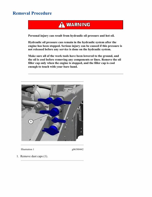
– Quick Coupler – Remove and Install
– Quick Coupler – Remove and Install – Quick Disconnect
– Refrigerant Condenser – Remove and Install
– Ride Control Valve – Remove and Install
– Seat – Remove and Install
– Tilt Cylinder – Remove and Install
– Window Wiper Motor – Remove and Install
Disassembly and Assembly C3.3B Engines for Caterpillar Built Machines
– Alternator – Remove and Install
– Bearing Clearance – Check
– Boost Pressure Sensor – Remove and Install
– Bridge Dowels – Remove and Install
– Camshaft and Valve Lifters – Remove and Install
– Camshaft Gear – Remove and Install
– Camshaft Position Sensor – Remove and Install
– Camshaft Position Sensor Bushing – Remove and Install
– Connecting Rod Bearings – Remove and Install
– Coolant Temperature Sensor – Remove and Install
– Crankshaft and Main Bearings – Install
– Crankshaft and Main Bearings – Remove
– Crankshaft Front Seal – Remove and Install
– Crankshaft Position Sensor – Remove and Install
– Crankshaft Pulley – Remove and Install
– Crankshaft Rear Seal and Wear Sleeve – Install – Includes
– Crankshaft Rear Seal and Wear Sleeve – Remove – Includes
– Cylinder Head – Remove and Install
– Diesel Particulate Filter – Assemble
– Diesel Particulate Filter – Disassemble
– Diesel Particulate Filter – Remove and Install
– Electric Starting Motor – Remove and Install
– Electronic Unit Injector – Remove and Install
– Engine Oil Cooler – Remove and Install
– Engine Oil Pan – Remove and Install
– Engine Oil Pressure Sensor – Remove and Install
– Engine Oil Pump – Remove and Install
– Engine Oil Relief Valve – Remove and Install
– Exhaust Gas Recirculation Valve – Remove and Install
– Exhaust Manifold – Remove and Install
– Flywheel – Remove and Install
– Flywheel Housing – Remove and Install
– Fuel Injection Lines – Remove and Install
– Fuel Injection Pump – Remove and Install
– Fuel Manifold (Rail) – Remove and Install
– Fuel Manifold (Rail) – Remove and Install
– Fumes Disposal Filter – Remove and Install
– Glow Plugs – Remove and Install
– Housing (Front) – Remove and Install
– Idler Gear – Remove and Install
– Inlet Air Temperature Sensor – Remove and Install
– Inlet and Exhaust Valve Guides – Remove and Install
– Inlet and Exhaust Valve Springs – Remove and Install
– Inlet and Exhaust Valves – Remove and Install
– Inlet Manifold – Remove and Install
– Pistons and Connecting Rods – Assemble
– Pistons and Connecting Rods – Disassemble
– Pistons and Connecting Rods – Remove and Install
– Pressure Sensor (Mass Air Flow) – Remove and Install
– Rocker Shaft – Assemble
– Rocker Shaft – Disassemble
– Rocker Shaft and Push Rod – Remove and Install
– Turbocharger – Remove and Install
– V-Belts – Remove and Install
– Valve Mechanism Cover – Remove and Install
– Water Pump – Remove and Install
– Water Temperature Regulator – Remove and Install
Schematic Caterpillar 236D3, 242D3, 246D3, 262D3, 272D3 and 272D3 XE, 257D3, and 259D3, 279D3, 289D3, 299D3 and 299D3 XE Hydraulic System
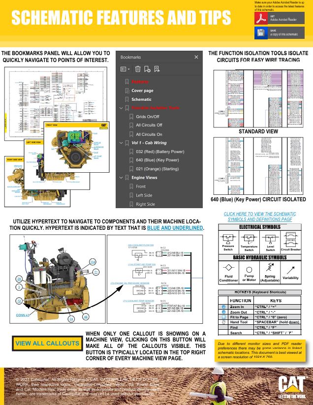
– Features
– Cover Page
– Information
– Component Location
– Vol 1 – Standard Implements
– Vol 2 – High Flow Implements
– Tap Location
– Vol 1 – Standard Implements
– Vol 2 – High Flow Implements
– Schematics
– Function Isolation Tools
– Grids On/Off
– All Circuits Off
– All Circuits On
– Vol 1 – Standard Implements
– 021 (Orange) (Pilot Control Circuit)
– 032 (Red) (Main Pump Output)
– 141 (Lt Orange) (Tilt Cylinder Circuit)
– 190 (Dk Pink) (Charge Pump Output)
– 258 (Dk Purple) (Hydraulic Fan Circuit)
– 305 (Lt Blue) (Load Sense Circuit)
– 347 (Dk Green) (Supply Line)
– 464 (Brown) (Quick Coupler Circuit)
– 577 (Lt Green) (Drain/Return Line)
– 613 (Dk Yellow) (Steering Circuit)
– 640 (Blue) (Travel Control Circuit)
– 5767 (Olive Green) (Lift Cylinder Circuit)
– Vol 2 – High Flow Implements
– 021 (Orange) (Pilot Control Circuit)
– 032 (Red) (Main Pump Output)
– 141 (Lt Orange) (Tilt Cylinder Circuit)
– 190 (Dk Pink) (Charge Pump Output)
– 258 (Dk Purple) (Hydraulic Fan Circuit)
– 305 (Lt Blue) (Load Sense Circuit)
– 347 (Dk Green) (Supply Line)
– 464 (Brown) (Quick Coupler Circuit)
– 577 (Lt Green) (Drain/Return Line)
– 613 (Dk Yellow) (Steering Circuit)
– 640 (Blue) (Travel Control Circuit)
– 5767 (Olive Green) (Lift Cylinder Circuit)
– CON 522 (Lt Purple/Black Stripe) (Coupler Cylinder Circuit)
– Machine Views
– Vol 1 – Standard Implements
– Machine – Front View
– Machine – Rear View
– Machine – Right View
– Vol 2 – High Flow Implements
– Machine – Front View
– Machine – Rear View
– Machine – Right View
Schematic Caterpillar 236D3, 242D3, 246D3, 262D3, 272D3 and 273D3 XE, 257D3, and 259D3, 279D3 289D3, 299D3 and 299D3 XE Electrical System
– Features
– Cover Page
– Information
– Component Location
– Vol 1 – Cab Wiring
– Vol 2 – Chassis and Engine Wiring
– Vol 3 – Engine (Beta+) Wiring and Aftertreatment Control Unit
– Connector Location
– Vol 1 – Cab Wiring
– Vol 2 – Chassis and Engine Wiring
– Vol 3 – Engine (Beta+) Wiring and Aftertreatment Control Unit
– Schematics
– Function Isolation Tools
– Grids On/Off
– All Circuits Off
– All Circuits On
– Vol 1 – Cab Wiring
– Unspecified Circuit
– Black (Ground)
– 032 (Red) (Battery Power)
– 640 (Blue) (Key Power)
– 021 (Orange) (Starting)
– 258 (Dk Purple) (Machine Control)
– 509 (Lt Pink) (Engine Master)
– 613 (Dk Yellow) (Heat/AC)
– 4665 (Tan) (Turn/Wiper/Washer)
– CON 346 (CAT D.L.)
– CON 509 (J1939/1587 D.L.)
– CON 522 (CAN “B” D.L.)
– SUB 651 (Blue Gray) (Ethernet)
– Vol 2 – Chassis and Engine Wiring
– Unspecified Circuit
– Black (Ground)
– 032 (Red) (Battery Power)
– 640 (Blue) (Key Power)
– 021 (Orange) (Starting)
– 190 (Dk Pink) (Start Aid)
– 258 (Dk Purple) (Machine Control)
– 509 (Lt Pink) (Engine Master)
– 613 (Dk Yellow) (Heat/AC)
– CON 509 (J1939/1587 D.L.)
– CON 522 (CAN “B” D.L.)
– CON 305 (CAN “D” D.L.)
– Vol 3 – Engine (Beta+) Wiring and Aftertreatment Control Unit
– Unspecified Circuit
– Black (Ground)
– 032 (Red) (Battery Power)
– 640 (Blue) (Key Power)
– 021 (Orange) (Starting)
– 190 (Dk Pink) (Start Aid)
– 258 (Dk Purple) (Machine Control)
– 509 (Lt Pink) (Engine Master)
– CON 509 (J1939/1587 D.L.)
– CON 522 (CAN “B” D.L.)
– CON 305 (CAN “D” D.L.)
– SUB 522 (Lt Purple) (Aftertreatment)
– Machine Views
– Vol 1 – Cab Wiring
– Cab – Front View (Without Seat)
– Cab – Front View
– Cab – Left Side View
– Cab – Rear View
– Machine – Rear View
– Vol 2 – Chassis and Engine Wiring
– Chassis Front Top View
– Engine Left Side View
– Engine Right Side View
– Engine Top View
– Machine Left Rear View
– Machine Left Side View
– Machine Right Side View (HVAC Wiring)
– Machine Right Side View
– Main Control Valve – STD Flow
– Main Control Valve – XPS
– Vol 3 – Engine (Beta+) Wiring and Aftertreatment Control Unit
– Chassis – Left Side View
– Engine – Left Side View
– Engine – Right Side View
– Engine – Top View
– Machine – Front View
– Machine – Rear Left View
– Machine – Rear Right View
Schematic Caterpillar 236D3, 242D3, 246D3, 262D3, 272D3, and 272D3 XE, 257D3, and 259D3, 279D3, 289D3, 299D3 and 299D3 XE Electrical System
– Features
– Cover Page
– Information
– Component Location
– Vol 1 – Cab Wiring
– Vol 2 – Chassis and Engine Wiring
– Vol 3 – Engine (Beta+) Wiring and Aftertreatment Control Unit
– Connector Location
– Vol 1 – Cab Wiring
– Vol 2 – Chassis and Engine Wiring
– Vol 3 – Engine (Beta+) Wiring and Aftertreatment Control Unit
– Schematics
– Function Isolation Tools
– Grids On/Off
– All Circuits Off
– All Circuits On
– Vol 1 – Cab Wiring
– Black (Ground)
– 032 (Red) (Battery Power)
– 640 (Blue) (Key Power)
– 021 (Orange) (Starting)
– 258 (Dk Purple) (Xmsn/Machine/Engine Pump)
– 509 (Lt Pink) (Engine Master)
– 613 (Dk Yellow) (Heat/AC)
– 4665 (Tan) (Turn/Wiper/Washer)
– CON 346 (CAT D.L.)
– CON 509 (J1939/1587 D.L.)
– CON 522 (CAN “B” D.L.)
– Unspecified Circuit
– SUB 651 (Blue Gray) (Ethernet)
– Vol 2 – Chassis and Engine Wiring
– Black (Ground)
– 032 (Red) (Battery Power)
– 640 (Blue) (Key Power)
– 021 (Orange) (Starting)
– 190 (Dk Pink) (Start Aid)
– 258 (Dk Purple) (Xmsn/Machine/Engine Pump)
– 509 (Lt Pink) (Engine Master)
– 613 (Dk Yellow) (Heat/AC)
– CON 509 (J1939/1587 D.L.)
– CON 522 (CAN “B” D.L.)
– CON 305 (CAN “D” D.L.)
– Unspecified Circuit
– Vol 3 – Engine (Beta+) Wiring and Aftertreatment Control Unit
– Black (Ground)
– 032 (Red) (Battery Power)
– 640 (Blue) (Key Power)
– 021 (Orange) (Starting)
– 190 (Dk Pink) (Start Aid)
– 258 (Dk Purple) (Xmsn/Machine/Engine Pump)
– 509 (Lt Pink) (Engine Master)
– CON 509 (J1939/1587 D.L.)
– CON 522 (CAN “B” D.L.)
– CON 305 (CAN “D” D.L.)
– Unspecified Circuit
– SUB 522 (Lt Purple) (Aftertreatment)
– Machine Views
– Vol 1 – Cab Wiring
– Cab – Front View (Without Seat)
– Cab – Front View
– Cab – Left Side View
– Cab – Rear View
– Machine – Rear View
– Vol 2 – Chassis and Engine Wiring
– Chassis Front Top View
– Engine Left Side View
– Engine Right Side View
– Engine Top View
– Machine Left Rear View
– Machine Left Side View
– Machine Right Side View (HVAC Wiring)
– Machine Right Side View
– Main Control Valve – STD Flow
– Main Control Valve – XPS
– Vol 3 – Engine (Beta+) Wiring and Aftertreatment Control Unit
– Chassis – Left Side View
– Engine – Left Side View
– Engine – Right Side View
– Engine – Top View
– Machine – Front View
– Machine – Rear Left View
– Machine – Rear Right View
Specifications C3.3B Engines for Caterpillar Built Machines
– Alternator and Regulator
– Boost Pressure Sensor
– Camshaft
– Connecting Rod
– Coolant Temperature Sensor
– Crankcase Breather
– Crankshaft
– Cylinder Block
– Cylinder Head
– Cylinder Head Valves
– Diesel Particulate Filter
– Electric Starting Motor
– Engine Design
– Engine Design
– Engine Oil Cooler
– Engine Oil Pan
– Engine Oil Pump
– Exhaust Manifold
– Flywheel
– Flywheel Housing
– Fuel Injection Lines
– Fuel Injector
– Gear Group (Front)
– Piston and Rings
– Speed/Timing Sensor
– Valve Mechanism
– Valve Mechanism Cover
– Water Temperature Regulator
Systems Operation, Testing and Adjusting C3.3B Engines for Caterpillar Built Machines
– Air in Fuel – Test
– Air Inlet and Exhaust System
– Air Inlet and Exhaust System – Inspect
– Alternator – Test
– Basic Engine
– Battery – Test
– Compression – Test
– Connecting Rod Bearings – Inspect
– Cooling System
– Cooling System – Check – Overheating
– Cooling System – Inspect
– Cooling System – Test
– Cylinder Block – Inspect
– Electric Starting System – Test
– Electrical System
– Engine Crankcase Pressure (Blowby) – Test
– Engine Oil Pressure – Test
– Engine Oil Pump – Inspect
– Engine Speed – Check
– Engine Valve Lash – Inspect/Adjust – C3.3B Engines
– Excessive Bearing Wear – Inspect
– Excessive Engine Oil Consumption – Inspect
– Exhaust Temperature – Test
– Finding Top Center Position for No. 4 Piston
– Fuel Injector – Test
– Fuel Quality – Test
– Fuel System
– Fuel System – Inspect
– Fuel System – Inspect
– General Information
– General Information
– Lubrication System
– Main Bearings – Inspect
– Piston Ring Groove – Inspect
– Turbocharger – Inspect
– Water Temperature Regulator – Test
Troubleshooting C3.3B and C3.8 Engines for Caterpillar Built Machines
– Acceleration Is Poor or Throttle Response Is Poor
– Alternator Problem – Charging Problem and/or Noisy
– Battery Problem
– Cat ET Service Features – DEF Dosing System Test
– Component Location
– Coolant Contains Oil
– Coolant Level Is Low
– Coolant Temperature Is High
– Cooling Fan Is Always ON
– Cylinder Is Noisy
– Data Link – Test
– DEF Concentration Is Incorrect
– DEF Injector Trim File – Install – Injector Trim Code – Install
– DEF Line Heater – Test
– DEF Module Does Not Respond
– DEF Pressure Is High
– DEF Pressure Is Low
– DEF Pump – Test
– DEF Tank Level Is Low
– DEF Tank Temperature Is High
– DEF Tank Temperature Is Low
– Diagnostic Capabilities
– Diagnostic Trouble Codes
– Diesel Particulate Filter Active Regeneration Occurrence Is
– Diesel Particulate Filter Error
– Diesel Particulate Filter Regeneration Does Not Occur
– ECM – Replace
– ECM Memory – Test
– ECM Software – Install
– Electrical Connectors
– Electrical Connectors – Inspect
– Electrical Power Supply – Test
– Electronic Service Tool Does Not Communicate
– Electronic Service Tools
– Engine Cranks but Does Not Start
– Engine Does Not Crank
– Engine Has Early Wear
– Engine Has Mechanical Noise (Knock)
– Engine Injector Trim File – Install
– Engine Misfires, Runs Rough or Is Unstable
– Engine Misfires, Runs Rough or Is Unstable
– Engine Monitoring System
– Engine Overspeeds
– Engine Shutdown Occurs Intermittently
– Engine Stalls at Low RPM
– Engine Top Speed Is Not Obtained
– Engine Vibration Is Excessive
– Exhaust Has Excessive White Smoke
– Exhaust System Contains Oil
– Exhaust Temperature Is High
– Fuel Consumption Is Excessive
– Fuel Rail Pressure Is High
– Fuel Rail Pressure Is Low
– Fuel Rail Temperature Is High
– General Information
– Injector Data Incorrect – Test
– Injector Data Incorrect – Test
– Injector Solenoid – Test
– Injector Solenoid – Test – Fuel Injector
– Injector Trim File – Install
– Intake Manifold Air Temperature Is High
– Motorized Valve – Test
– NOx Conversion Is Low
– NOx Reduction System (NRS) – Test
– NOx Sensor – Test
– Oil Consumption Is Excessive
– Oil Contains Coolant
– Oil Contains Fuel
– Oil Pressure Is Low
– Relay – Test – ECM Main Relay
– SCR Catalyst Has Incorrect Inlet Temperature
– Sensor Signal (Analog, Active) – Test
– Sensor Signal (Analog, Passive) – Test
– Sensor Supply – Test
– Service Information Report
– Solenoid Valve – Test – Pressure Relief Valve
– Solenoid Valve – Test – Solenoid Valves that Connect to the
– Solenoid Valve – Test – Solenoid Valves that Connect to the
– Solenoid Valve – Test – Suction Control Valve
– Speed/Timing – Test
– Starting Aid – Test
– Test ECM Mode
– Turbocharger Failure
– Valve Lash Is Excessive
– Welding Precaution

Service manual Caterpillar 279D3 Compact Track Loader with C3.3B Engine | RB900001-UP
24,99 $
Format: PDF
Type: Service Manual
Pages: 3652
Size: 177 Mb
No.: RB900001-UP
-
 Service manual Caterpillar D6R SERIES II TRACK-TYPE TRACTOR /DS XL, DS XW with C-9 ENGINE | BRZ00001-UP
24,99 $
ADD TO CART
-
 Service manual Caterpillar DP60NMS Forklift Lift Truck
19,99 $
ADD TO CART
-
 Service manual Caterpillar D6T Track-Type Tractor XL VPAT, XW VPAT, LGP VPAT with C9.3 Engine | RA900001-UP
24,99 $
ADD TO CART
-
 Service manual Caterpillar 323F SA Excavator with C4.4 Engine | FA200001-10100
24,99 $
ADD TO CART
-
 Schematic Caterpillar 326D2 & 330D2 Excavator (Electrical System) | UENR8004-01
9,99 $
ADD TO CART
-
 Service manual Caterpillar 320D & 320D L Excavators with C6.6 Engine | MZD00001-UP
24,99 $
ADD TO CART
Reviews
There are no reviews yet.