Air Conditioning and Heating R134a for All Cat Machines
– General Information
– Refrigerant Orifice Tube System
– Refrigerant Compressor
– Refrigerant Compressor
– Refrigerant Compressor
– Refrigerant Condenser
– Refrigerant Condenser
– Refrigerant Receiver-Dryer
– Refrigerant Receiver-Dryer
– Refrigerant Expansion Valve
– In-line Refrigerant Dryer
– Identifying the Refrigerant
– In-line Refrigerant Dryer
– Refrigerant Orifice Tube Assembly
– Refrigerant Orifice Tube Assembly
– Evaporator Coil
– Refrigerant Accumulator
– Refrigerant Accumulator
– Refrigerant Accumulator
– Refrigerant Compressor Protection System
– Temperature Control
– Temperature Control
– Identifying the Refrigerant
– Pressure Switch (Refrigerant)
– Pressure Switch (Refrigerant)
– Cab Pressurization and Filtration System
– Cab Pressurization and Filtration System
– Cab Pressurization and Filtration System
– Condensate Drainage System
– Condensate Drainage System
– Service Intervals
– Service Intervals
– Glossary of Terms
– Identifying the Air Conditioning System
– General Troubleshooting Information
– General Troubleshooting Information
– Machine Preparation for Testing and Adjusting
– Machine Preparation for Testing and Adjusting
– Air Conditioning Performance – Test
– Refrigerant Leakage – Test
– Manifold Gauge Set (Refrigerant) – Install
– Manifold Gauge Set (Refrigerant) – Install
– Refrigerant Recovery
– Refrigerant Recovery
– Identifying the Air Conditioning System
– Refrigerant System – Flush
– Refrigerant Oil – Test
– Refrigerant Compressor – Test
– Refrigerant Compressor – Test
– Refrigerant Compressor – Test
– Refrigerant System – Evacuate
– Refrigerant System – Evacuate
– Refrigerant System – Charge
– Refrigerant System – Charge
– Manifold Gauge Set (Refrigerant) – Remove
– Identifying the Heating System
– Manifold Gauge Set (Refrigerant) – Remove
– Compressor Protection System – Test
– Compressor Protection System – Test
– Electronic Heat Control – Test
– Electronic Heat Control – Test
– Heater Performance – Test
– Heating and Air Conditioning Service Publications
– General Information
– General Information
– Machine Preparation for Disassembly and Assembly
– Refrigerant Expansion Valve System
– Air Conditioner Lines – Remove and Install
– Refrigerant Compressor – Remove and Install
– Refrigerant Accumulator – Remove and Install
– Refrigerant Expansion Valve – Remove and Install
– Refrigerant Receiver-Dryer – Remove and Install
– In-Line Refrigerant Dryer – Remove and Install
– Refrigerant Orifice Tube Assembly – Remove and Install
– Refrigerant Expansion Valve System
– Refrigerant Orifice Tube System
– General Information
Disassembly and Assembly 301.5,301.6,301.7,301.8,302 Mini Hydraulic Excavator Engine Supplement
– Air Cleaner – Remove and Install
– Alternator – Remove and Install
– Battery – Remove and Install
– Cooling System Package (Radiator, Hydraulic Oil Cooler) –
– Electric Starting Motor – Remove and Install
– Electronic Control Module – Remove and Install
– Engine – Remove and Install
– Fuel Filter and Base – Remove and Install
– Refrigerant Compressor – Remove and Install
– System Pressure – Release
Disassembly and Assembly 301.5,301.6,301.7,301.8,302 Mini Hydraulic Excavator Machine Systems
– Accumulator – Remove and Install
– Blade – Remove and Install
– Blade Cylinder – Assemble
– Blade Cylinder – Disassemble
– Blade Cylinder – Remove and Install
– Boom – Remove and Install
– Boom Cylinder – Assemble
– Boom Cylinder – Disassemble
– Boom Cylinder – Remove and Install
– Boom Swing Cylinder – Assemble
– Boom Swing Cylinder – Disassemble
– Boom Swing Cylinder – Remove and Install
– Bucket – Remove
– Bucket – Remove and Install
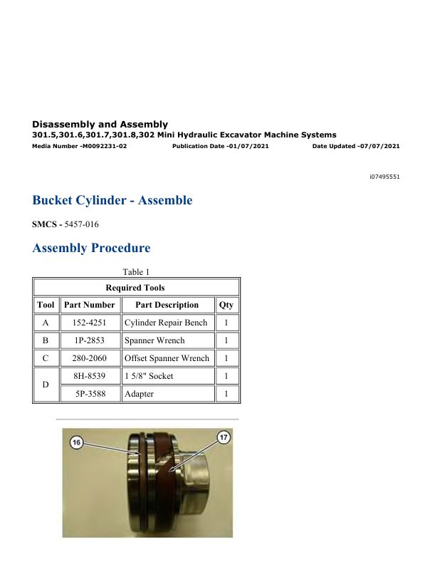
– Bucket Cylinder – Assemble
– Bucket Cylinder – Disassemble
– Bucket Cylinder – Remove and Install
– Bucket Linkage – Remove and Install
– Cab – Remove and Install
– Cab Heater – Remove and Install
– Canopy – Remove and Install
– Canopy – Remove and Install
– Counterweight – Remove and Install
– Final Drive – Assemble
– Final Drive – Disassemble
– Final Drive – Remove and Install
– Final Drive Sprocket – Remove and Install
– Front Idler and Track Adjuster – Remove
– Fuel Tank – Remove and Install
– Hydraulic Lockout Control – Remove and Install
– Hydraulic System Pressure – Release
– Hydraulic Tank – Remove and Install
– Main Control Valve – Assemble
– Main Control Valve – Disassemble
– Main Control Valve – Remove and Install
– Main Hydraulic Pump – Assemble
– Main Hydraulic Pump – Disassemble
– Main Hydraulic Pump – Remove and Install
– Piston Motor (Swing) – Assemble
– Piston Motor (Swing) – Disassemble
– Recoil Spring – Disassemble and Assemble
– Seat – Remove and Install
– Stick – Remove and Install
– Stick Cylinder – Assemble
– Stick Cylinder – Disassemble
– Stick Cylinder – Remove and Install
– Swing Drive – Remove and Install
– Swing Gear and Bearing – Remove and Install
– Swivel – Assemble
– Swivel – Disassemble
– Swivel – Remove and Install
– System Pressure – Release
– Track – Remove and Install
– Track Roller – Remove and Install
– Track Roller Frame – Remove and Install
– Undercarriage Cylinder (Adjustable Gauge) – Assemble
– Undercarriage Cylinder (Adjustable Gauge) – Disassemble
– Undercarriage Cylinder (Adjustable Gauge) – Remove and
– Upper Frame and Undercarriage Frame – Connect
– Upper Frame and Undercarriage Frame – Separate
– Window Wiper Motor – Remove and Install
Disassembly and Assembly C1.1, C1.5 and C2.2 Engines for Caterpillar Built Machines
– Alternator – Remove and Install – 14 Amp and 15 Amp
– Alternator – Remove and Install – 40 Amp Alternator
– Alternator – Remove and Install – 55 Amp Alternator
– Alternator – Remove and Install – 65 Amp and 85 Amp
– Bearing Clearance – Check
– Camshaft – Assemble
– Camshaft – Disassemble
– Camshaft – Install
– Camshaft – Remove
– Connecting Rod Bearings – Install – Connecting rods in position
– Connecting Rod Bearings – Remove – Connecting rods in
– Coolant Temperature Switch – Remove and Install
– Crankcase Breather – Remove and Install – Naturally Aspirated
– Crankcase Breather – Remove and Install – Turbocharged
– Crankshaft – Install
– Crankshaft – Remove
– Crankshaft Front Seal – Remove and Install
– Crankshaft Main Bearings – Install
– Crankshaft Main Bearings – Remove
– Crankshaft Pulley – Remove and Install
– Crankshaft Rear Seal – Remove and Install
– Crankshaft Wear Sleeve (Rear) – Remove and Install
– Cylinder Head – Install
– Cylinder Head – Install – C1.1 Engine
– Cylinder Head – Remove
– Cylinder Head – Remove – C1.1 Engine
– Electric Starting Motor – Remove and Install
– Engine Oil Cooler – Remove and Install
– Engine Oil Line – Remove and Install
– Engine Oil Pan – Remove and Install
– Engine Oil Pressure Switch – Remove and Install
– Engine Oil Pump – Install
– Engine Oil Pump – Remove – C1.1, C1.5, and C2.2 Engines
– Engine Oil Relief Valve – Remove and Install
– Exhaust Manifold – Remove and Install
– Fan – Remove and Install
– Flywheel – Install
– Flywheel – Remove
– Flywheel Housing – Remove and Install
– Flywheel Housing – Remove and Install – Engines with Flywheel
– Fuel Filter Base – Remove and Install
– Fuel Injection Lines – Remove and Install
– Fuel Injection Pump – Remove and Install
– Fuel Injector – Remove and Install
– Fuel Shutoff Solenoid – Remove and Install
– Fuel Transfer Pump – Remove and Install – Electrical Fuel
– Fuel Transfer Pump – Remove and Install – Mechanical Fuel
– Glow Plugs – Remove and Install
– Housing (Front) – Assemble
– Housing (Front) – Disassemble
– Housing (Front) – Install
– Housing (Front) – Remove
– Inlet and Exhaust Valve Springs – Remove and Install
– Inlet and Exhaust Valves – Remove and Install
– Lifter Group – Remove and Install
– Pistons and Connecting Rods – Assemble
– Pistons and Connecting Rods – Disassemble
– Pistons and Connecting Rods – Install
– Pistons and Connecting Rods – Remove
– Rocker Shaft – Assemble – C1.1 Engine
– Rocker Shaft – Assemble – C1.5 and C2.2 Engines
– Rocker Shaft – Disassemble – C1.1 Engine
– Rocker Shaft – Disassemble – C1.5 and C2.2 Engines
– Rocker Shaft and Pushrod – Install
– Rocker Shaft and Pushrod – Remove
– Turbocharger – Remove and Install
– V-Belts – Remove and Install
– Valve Mechanism Cover – Remove and Install
– Water Pump – Remove and Install – C1.1 Engine
– Water Pump – Remove and Install – C1.5 and C2.2 Engines
– Water Temperature Regulator – Remove and Install
– Water Temperature Regulator Housing – Remove and Install
Schematic Caterpillar 301.5, 301.6, 301.7 CR, 301.8, and 302 CR Mini Hydraulic Excavator Electrical System
Schematic Caterpillar 301.5, 301.6, 301.7CR, 301.8 and 302CR Mini Hydraulic Excavator Hydraulic System
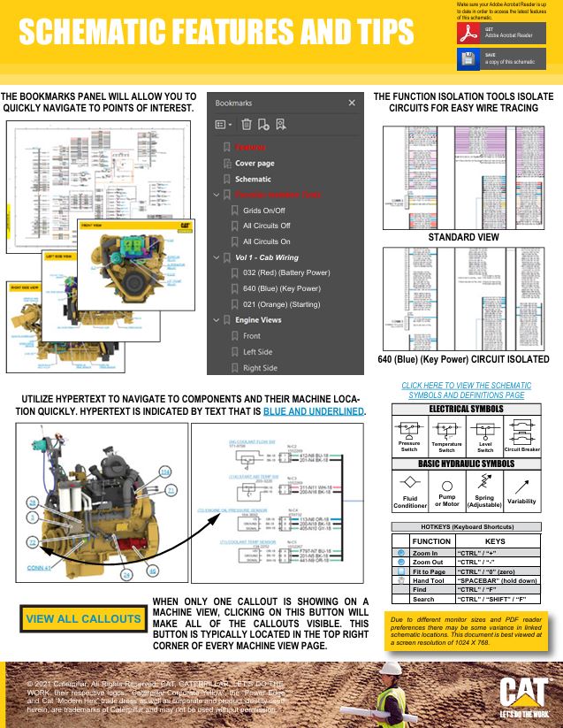
– Features
– Cover Page
– Information
– Component Location
– Tap Location
– Schematic
– Machine Views
– Machine – Front View
– Machine – Right Side View
– Machine – Left Side View
– Undercarriage – Top View
Schematic Caterpillar 301.5, 301.6, and 301.7 CR Mini Hydraulic Excavator Electrical System
– Features
– Cover Page
– Information
– Component Location
– Vol 1 – Cab Wiring
– Vol 2 – Canopy Wiring
– Connector Location
– Vol 1 – Cab Wiring
– Vol 2 – Canopy Wiring
– Schematics
– Function Isolation Tools
– Grids On/Off
– All Circuits Off
– All Circuits On
– Vol 1 – Cab Wiring
– Unspecified Circuit
– Black (Ground)
– 032 (Red) (Battery Power)
– 640 (Blue) (Key Power)
– 021 (Orange) (Starting)
– 190 (Dk Pink) (Start Aid)
– 258 (Dk Purple) (Machine Control)
– 346 (Med Green) (Monitor)
– 613 (Dk Yellow) (Heat/AC)
– 4665 (Tan) (Wiper Washer Circuit)
– CON 509 (J1939/1587 D.L.)
– CON 522 (CAN “B” D.L.)
– SUB 651 (Blue Gray) (Ethernet)
– Vol 2 – Canopy Wiring
– Unspecified Circuit
– Black (Ground)
– 032 (Red) (Battery Power)
– 640 (Blue) (Key Power)
– 021 (Orange) (Starting)
– 190 (Dk Pink) (Start Aid)
– 258 (Dk Purple) (Machine Control)
– 346 (Med Green) (Monitor)
– CON 509 (J1939/1587 D.L.)
– SUB 651 (Blue Gray) (Ethernet)
– Machine Views
– Vol 1 – Cab Wiring
– Front Linkage – Boom
– Fuse Block
– Machine – Front View
– Machine – Left Side View
– Machine – Rear View
– Vol 2 – Canopy Wiring
– Machine Front View
– Machine Front Left View
– Machine Left Side View
– Machine Rear View
Specifications 301.5, 301.6, 301.7CR, 301.8, 302CR Mini Hydraulic Excavators Machine System
– Air Conditioner and Mounting
– Air Conditioner Lines
– Blade Cylinder
– Blade Mounting
– Blade Mounting
– Boom
– Boom Cylinder
– Boom Cylinder
– Bucket Cylinder
– Bucket Cylinder
– Bucket Lines
– Bucket Linkage
– Cab Trim
– Cab Window
– Diverter Valve
– Frame (Undercarriage)
– Front Guard
– Hydraulic Cylinder
– Hydraulic Tank and Filter
– Joystick Control
– Main Hydraulic Pump and Mounting
– Pedal Control (Auxiliary)
– Pedal Control (Auxiliary)
– Pilot Lines
– Piston Pump
– Pump Control Valve
– Pump Lines
– Radiator and Hydraulic Oil Cooler
– Relief Valve
– Return Lines
– Rollover Protective Structure (ROPS) Mounting
– Seat Mounting
– Stick
– Stick Cylinder
– Stick Cylinder
– Stick Cylinder
– Swing Frame
– Travel Alarm
– Undercarriage Cylinder (Adjustable Gauge)
Specifications C1.1, C1.5 and C2.2 Engines for Caterpillar Built Machines
– Alternator and Regulator
– Belt Tension Chart
– Camshaft
– Connecting Rod
– Connecting Rod Bearing Journal
– Coolant Temperature Switch
– Crankshaft
– Crankshaft Pulley
– Cylinder Block
– Cylinder Head
– Cylinder Head Valves
– Electric Starting Motor
– Engine Design
– Engine Lifting Bracket
– Engine Oil Filter
– Engine Oil Lines
– Engine Oil Pan
– Engine Oil Pressure Switch
– Engine Oil Pump
– Engine Oil Relief Valve
– Exhaust Manifold
– Fan Drive
– Flywheel
– Flywheel Housing
– Fuel Injection Lines
– Fuel Injection Nozzles
– Fuel Injection Pump
– Fuel Shutoff Solenoid
– Fuel Transfer Pump
– Gear Group (Front)
– Glow Plugs
– Governor Control – Actuator
– Housing (Front)
– Lifter Group
– Main Bearing Journal
– Piston and Rings
– Rocker Shaft
– Turbocharger
– Valve Mechanism Cover
– Water Temperature Regulator
Systems Operation & Testing and Adjusting 301.5, 301.6, 301.7 CR, 301.8, and 302 CR Mini Hydraulic Excavator Machine System
– Accumulator (Pilot)
– Accumulator (Pilot) – Test and Charge
– Blade Cylinder
– Blade Hydraulic System
– Boom Cylinder
– Boom Cylinder – Swing Boom
– Boom System
– Bucket Cylinder
– Bucket System
– Check Valve (Return Makeup) – Bypass Check Valve
– Control Valve (Boom Lowering)
– Control Valve (Stick Lowering)
– Cutoff Pressure (Main Pump) – Test and Adjust
– Cylinder Drift – Check
– Cylinder Speed – Check
– Displacement Change Valve
– Electronic Control (Blade System)
– Electronic Control (Boom System)
– Electronic Control (Bucket System)
– Electronic Control (Machine System)
– Electronic Control (Main Control Valve)
– Electronic Control (Main Pump System)
– Electronic Control (Pilot System)
– Electronic Control (Stick System)
– Electronic Control (Swing System)
– Electronic Control (Travel System)
– Engine Control
– Engine Performance – Test – Engine Speed
– Final Drive
– General Calibration Information – Calibration of Travel Speed
– General Calibration Information – Cat ET
– General Information (Blade System)
– General Information (Boom System)
– General Information (Bucket System)
– General Information (Machine System)
– General Information (Main Control Valve)
– General Information (Main Pump System)
– General Information (Pilot System)
– General Information (Return System)
– General Information (Stick System)
– General Information (Swing System)
– General Information (Travel System)
– General Testing and Adjusting Information
– Graphic Color Codes
– Hydraulic Oil Cooler
– Hydraulic System Air – Purge
– Hydraulic Tank and Filter
– Joystick Control
– Machine Drift on a Slope – Check
– Machine System
– Main Control Valve
– Main Hydraulic Pump
– Main Hydraulic Pump Air – Purge
– Main Pump (Flow) – Test
– Margin Pressure – Test and Adjust
– Oil Makeup (Swing System)
– Oil Makeup (Travel System)
– Operational Checks
– Overload Warning – Set – If Equipped
– Pilot System
– Pilot Valve (Swing Parking Brake)
– Pressure Reducing Valve (Pilot Oil) – Test and Adjust
– Pump Control (Main Hydraulic)
– Quick Coupler System – Pilot Operated Quick Coupler (If
– Relief Valve (Line)
– Relief Valve (Line) – Test and Adjust
– Relief Valve (Swing)
– Relief Valve (Swing) – Test and Adjust
– Return Hydraulic System
– Solenoid Valve (Hydraulic Lockout)
– Specifications
– Stick Cylinder
– Stick System
– Swing Boom Hydraulic System
– Swing Drive
– Swing Motor
– Swing Motor – Test – Measurement of Case Drain Oil
– Swing Speed and Overswing on Level Ground – Check
– Swing Speed and Swing Drift on a Slope – Check
– Swing System
– Swivel
– System Pressure – Release
– Travel Counterbalance Valve
– Travel Motor
– Travel Motor – Test – Measurement of Case Drain Oil
– Travel on Level Ground – Test
– Travel on Level Ground – Test – Optional Test
– Travel Parking Brake
– Travel System
– Visual Inspection
– Work Tool Hydraulic System
Systems Operation & Testing and Adjusting C1.1, C1.5 and C2.2 Engines for Caterpillar Built Machines
– Air in Fuel – Test
– Air Inlet and Exhaust System
– Air Inlet and Exhaust System – Inspect
– Alternator – Test
– Basic Engine
– Battery – Test
– Charging System – Test
– Compression – Test
– Connecting Rod – Inspect
– Connecting Rod Bearings – Inspect
– Coolant Temperature Switch – Test
– Cooling System
– Cooling System – Check – Overheating
– Cooling System – Inspect
– Cooling System – Test
– Cylinder Block – Inspect
– Cylinder Head – Inspect
– Electric Starting System – Test
– Electrical System
– Engine Crankcase Pressure (Blowby) – Test
– Engine Oil Pressure – Test
– Engine Oil Pressure Switch – Test
– Engine Oil Pump – Inspect
– Engine Speed – Check
– Engine Valve Lash – Inspect/Adjust
– Excessive Bearing Wear – Inspect
– Excessive Engine Oil Consumption – Inspect
– Exhaust Temperature – Test
– Finding Top Center Position for No. 1 Piston
– Flywheel – Inspect
– Flywheel Housing – Inspect
– Fuel Injection Timing – Check
– Fuel Injector – Test
– Fuel Quality – Test
– Fuel Shutoff Solenoid – Test
– Fuel System
– Fuel System – Inspect
– Fuel System – Prime
– Fuel System Pressure – Test
– Fuel Transfer Pump – Test
– Gear Group (Front) – Time
– Gear Group – Inspect
– General Information
– Glow Plugs – Test
– Governor – Adjust
– Lubrication System
– Main Bearings – Inspect
– Piston Height – Inspect
– Piston Ring Groove – Inspect
– Troubleshooting
– Valve Depth – Inspect
– Valve Guide – Inspect
– Wastegate – Test
– Water Pump – Inspect
– Water Temperature Regulator – Test
Systems Operation Mini Hydraulic Excavator Monitoring System
– Prestart Monitoring Function
– Warning Operation
– Security System Password Entry
– Security System Password Entry
– Menu Outline
– System Schematic
– System Schematic
– General Information
Systems Operation Mini Hydraulic Excavator Monitoring System
– General Information
– Menu Outline
– Prestart Monitoring Function
– Security System Password Entry
– System Schematic
– Warning Operation
Troubleshooting 301.5, 301.6, 301.7 CR, 301.8, 302 CR, 306, 306.5, 307.5, 308, 308.5, 309, and 310 Mini Hydraulic Excavator
– Calibration Error Codes
– CAN Data Link – Test
– Connector Contact Description
– Connector Locations
– Determining Diagnostic Trouble Codes
– Diagnostic Capabilities
– Diagnostic Trouble Codes
– ECM – Configure
– ECM – Replace
– ECM Software – Install
– Electrical Connector – Inspect
– Emerging Symptom Information
– Ethernet Data Link – Test
– Event Codes
– General Information
– Joystick Control – Test
– Sensor Signal (Analog, Active) – Test
– Sensor Signal (Analog, Passive) – Test
– Sensor Signal (PWM) – Test
– Sensor Supply – Test
– Solenoid Valve – Test
– Switch Circuits – Test
– Symptom Troubleshooting
– System Schematic
– Wiring Harness (Open Circuit) – Test
– Wiring Harness (Short Circuit) – Test
Service manual Caterpillar 301.7CR Mini Hydraulic Excavator with C1.1 Engine | JH700001-UP
29,99 $
Format: PDF
Type: Service Manual
Pages: 2379
Size: 120 Mb
No.: JH700001-UP
-
 Service manual Caterpillar C9 Engines for Built Machines | RENR9579-22
14,99 $
ADD TO CART
Service manual Caterpillar C9 Engines for Built Machines | RENR9579-22
14,99 $
ADD TO CART -
 Service manual Caterpillar S4S Diesel Engine (Tier 2) | 99729-91100
12,99 $
ADD TO CART
Service manual Caterpillar S4S Diesel Engine (Tier 2) | 99729-91100
12,99 $
ADD TO CART -
 Service manual Caterpillar 320D2 & 320D2 L Excavators with C7.1 Engine | TMF00001-UP
29,99 $
ADD TO CART
Service manual Caterpillar 320D2 & 320D2 L Excavators with C7.1 Engine | TMF00001-UP
29,99 $
ADD TO CART -
 Schematic Caterpillar 320D2 Excavator Electrical System | UENR5969-03
9,99 $
ADD TO CART
Schematic Caterpillar 320D2 Excavator Electrical System | UENR5969-03
9,99 $
ADD TO CART -
 Service manual Caterpillar 938G II Wheel Loader with 3126B Engine | CRD00001-UP
29,99 $
ADD TO CART
Service manual Caterpillar 938G II Wheel Loader with 3126B Engine | CRD00001-UP
29,99 $
ADD TO CART -
 Schematic Caterpillar 320D2 Excavator Electrical System | UENR3604-03
4,99 $
ADD TO CART
Schematic Caterpillar 320D2 Excavator Electrical System | UENR3604-03
4,99 $
ADD TO CART
Reviews
There are no reviews yet.