308D, 314D, 321D and 328D Excavators Air Conditioning and Heating
– Actuator (Air Conditioner Control)
– Actuator Troubleshooting – Abnormal Detection
– Actuator Troubleshooting – Guide for Actuators
– Air Conditioner Lines
– Air Conditioner Lines
– Air Conditioner Lines
– Air Conditioner Lines
– Air Conditioner Lines
– Air Conditioning and Heating System Sensor Operation
– Air Conditioning System
– Air Conditioning System Troubleshooting – Guide for Sensors
– Blower Motor
– Blower Motor
– Control Module
– Control Module – Heater Only
– Control Panel
– Control Panel – Heater Only
– Evaporator Coil
– General Information
– General Troubleshooting Information
– Heater Core (Cab)
– Heater System (Cab) – Heater Only
– Machine Preparation for Troubleshooting
– Manifold Gauge Set (Refrigerant) – Install
– Manifold Gauge Set (Refrigerant) – Remove
– Pressure Switch (Refrigerant Pressure Cutoff)
– Pressure Switch (Refrigerant Pressure Cutoff)
– Refrigerant Compressor
– Refrigerant Compressor
– Refrigerant Compressor
– Refrigerant Compressor
– Refrigerant Compressor Oil – Check
– Refrigerant Condenser
– Refrigerant Condenser
– Refrigerant Expansion Valve
– Refrigerant Leakage – Test
– Refrigerant Receiver-Dryer
– Refrigerant Recovery
– Refrigerant System – Charge
– Refrigerant System – Evacuate
– Refrigerant System – Flush
– Required Tools
– Sensor Troubleshooting
– Speed Control – Power Transistor
– System Capacities for Refrigerant (Excavators) – 308D CR-
– Visual Inspection
4M40 DIESEL ENGINE SHOP MANUAL
– Cooling
– Electrical
– Engine
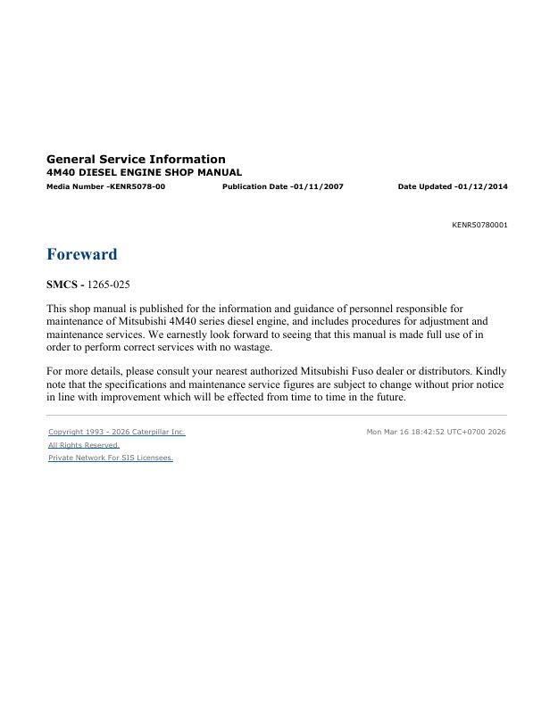
– Foreward
– Fuel and Engine Control
– General
– General
– General
– Intake And Exhaust
– Lubrication
– Systems Operation
– Testing and Adjusting
Air Conditioning and Heating R134a for All Caterpillar Machines
– Refrigerant Compressor
– System Capacities for Refrigerant (Off-Highway Trucks)
– General Information
– Identifying the Refrigerant
– Identifying the Air Conditioning System
– Identifying the Heating System
– Refrigerant Expansion Valve System
– Refrigerant Orifice Tube System
– Refrigerant Compressor
– Refrigerant Condenser
– Refrigerant Receiver-Dryer
– Refrigerant Compressor
– Refrigerant Expansion Valve
– In-line Refrigerant Dryer
– Refrigerant Orifice Tube Assembly
– Evaporator Coil
– Refrigerant Accumulator
– Refrigerant Compressor Protection System
– Temperature Control
– Pressure Switch (Refrigerant)
– Cab Pressurization and Filtration System
– Condensate Drainage System
– Refrigerant Compressor
– Service Intervals
– Glossary of Terms
– Required Tools
– Machine Preparation for Troubleshooting
– General Troubleshooting Information
– General Troubleshooting Information
– Visual Inspection (Troubleshooting)
– Air Conditioning System Troubleshooting
– Heating System Troubleshooting
– Automatic Temperature Control System (ECM Controlled)
– Refrigerant Compressor
– Troubleshooting Heating and Air Conditioning Control System
– Troubleshooting Heating and Air Conditioning Control System
– Automatic Temperature Control Panel Troubleshooting – 584
– Troubleshooting Condensate Drainage System
– Machine Preparation for Testing and Adjusting
– Air Conditioning Performance – Test
– Refrigerant Leakage – Test
– Manifold Gauge Set (Refrigerant) – Install
– Refrigerant Recovery
– Refrigerant System – Flush
– Refrigerant Compressor
– Refrigerant Oil – Test
– Refrigerant Compressor – Test
– Refrigerant System – Evacuate
– Refrigerant System – Charge
– Manifold Gauge Set (Refrigerant) – Remove
– Compressor Protection System – Test
– Electronic Heat Control – Test
– Heater Performance – Test
– Heating and Air Conditioning Service Publications
– General Information
– Refrigerant Compressor
– Machine Preparation for Disassembly and Assembly
– Air Conditioner Lines – Remove and Install
– Refrigerant Compressor – Remove and Install
– Refrigerant Accumulator – Remove and Install
– Refrigerant Expansion Valve – Remove and Install
– Refrigerant Receiver-Dryer – Remove and Install
– In-Line Refrigerant Dryer – Remove and Install
– Refrigerant Orifice Tube Assembly – Remove and Install
– Refrigerant Compressor
– System Capacities for Refrigerant (Motor Graders)
– System Capacities for Refrigerant (Off-Highway Trucks) –
– Refrigerant Compressor
Disassembly and Assembly 308D CR Excavator Engine Supplement
– Aftercooler – Remove and Install
– Air Cleaner – Remove and Install
– Alternator – Install
– Alternator – Remove
– Battery – Remove and Install
– Electric Starting Motor – Remove and Install
– Engine and Main Hydraulic Pump – Install
– Engine and Main Hydraulic Pump – Remove
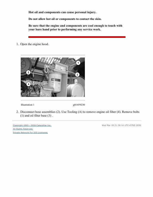
– Engine Oil Filter and Oil Filter Base – Install
– Engine Oil Filter and Oil Filter Base – Remove
– Engine Oil Filter Base – Assemble
– Engine Oil Filter Base – Disassemble
– Fuel Filter and Water Separator Base – Remove and Install
– Hood – Remove and Install
– Hydraulic Oil Cooler – Remove and Install
– Muffler – Remove and Install
– Radiator – Remove and Install
– Radiator and Hydraulic Oil Cooler – Install
– Radiator and Hydraulic Oil Cooler – Remove
– Refrigerant Compressor – Remove and Install
– Refrigerant Condenser – Remove and Install
– System Pressure – Release
– Turbocharger – Install
– Turbocharger – Remove
– Water Temperature Regulator – Remove and Install
Disassembly and Assembly 308D CR Excavator Machine Systems
– Accumulator – Remove and Install
– Blade – Remove and Install
– Blade Cylinder – Remove and Install
– Blower Motor (Air Conditioner, Heater) – Remove and Install
– Boom Cylinder – Remove and Install
– Bucket – Install
– Bucket – Remove
– Bucket Cylinder – Remove and Install
– Bucket Linkage – Install
– Bucket Linkage – Remove
– Cab – Install
– Cab – Remove
– Check Valve (Cooler Bypass) – Install
– Check Valve (Cooler Bypass) – Remove
– Check Valve (Slow Return) – Install
– Check Valve (Slow Return) – Remove
– Control Manifold (Pilot Oil) – Install
– Control Manifold (Pilot Oil) – Remove
– Counterweight – Remove and Install
– Duo-Cone Conventional Seals – Install
– Evaporator Coil – Install
– Evaporator Coil – Remove
– Final Drive and Travel Motor – Assemble
– Final Drive and Travel Motor – Disassemble
– Final Drive and Travel Motor – Install
– Final Drive and Travel Motor – Install
– Final Drive and Travel Motor – Remove
– Final Drive and Travel Motor – Remove
– Front Idler and Recoil Spring – Install
– Front Idler and Recoil Spring – Remove
– Fuel Tank – Install
– Fuel Tank – Remove
– Gear Pump (Pilot) – Install
– Gear Pump (Pilot) – Remove
– Heater Core – Install
– Heater Core – Remove
– Heating and Air Conditioning Unit – Install
– Heating and Air Conditioning Unit – Remove
– Hydraulic Lockout Control – Install
– Hydraulic Lockout Control – Remove
– Hydraulic Tank – Install
– Hydraulic Tank – Remove
– Hydraulic Track Adjusters – Install
– Hydraulic Track Adjusters – Remove
– Main Control Valve – Assemble
– Main Control Valve – Disassemble
– Main Control Valve – Install
– Main Control Valve – Remove
– Main Hydraulic Pump – Assemble
– Main Hydraulic Pump – Disassemble
– Main Hydraulic Pump – Install
– Main Hydraulic Pump – Remove
– Oil Filter and Base – Remove and Install
– Pilot Valve (Alternate Pattern Control) – Remove and Install
– Pilot Valve (Blade) – Assemble
– Pilot Valve (Blade) – Disassemble
– Pilot Valve (Blade) – Install
– Pilot Valve (Blade) – Remove
– Pilot Valve (Joystick) – Assemble
– Pilot Valve (Joystick) – Disassemble
– Pilot Valve (Joystick) – Install
– Pilot Valve (Joystick) – Remove
– Pilot Valve (Travel) – Assemble
– Pilot Valve (Travel) – Disassemble
– Pilot Valve (Travel) – Install
– Pilot Valve (Travel) – Remove
– Receiver Dryer (Refrigerant) – Remove and Install
– Recoil Spring – Assemble
– Recoil Spring – Disassemble
– Relief Valve (Pilot) – Remove and Install
– Seat – Remove and Install
– Seat Support – Remove and Install
– Seat Suspension – Remove and Install
– Solenoid Valve (Hydraulic Lockout) – Remove and Install
– Solenoid Valve (Swing Boom) – Assemble
– Solenoid Valve (Swing Boom) – Disassemble
– Solenoid Valve (Swing Boom) – Install
– Solenoid Valve (Swing Boom) – Remove
– Solenoid Valve (Travel Speed) – Remove and Install
– Solenoid Valve (Two-Way Flow and One Pump/Two Pump) –
– Solenoid Valve (Two-Way Flow and One Pump/Two Pump) –
– Solenoid Valve (Two-Way Flow and One Pump/Two Pump) –
– Solenoid Valve (Two-Way Flow and One Pump/Two Pump) –
– Sprocket – Remove and Install
– Stick – Install
– Stick – Remove
– Stick Cylinder – Remove and Install
– Support (Swing Boom) – Install
– Support (Swing Boom) – Remove
– Swing Boom – Install
– Swing Boom – Remove
– Swing Boom Cylinder – Remove and Install
– Swing Drive – Assemble
– Swing Drive – Disassemble
– Swing Drive – Install
– Swing Drive – Remove
– Swing Gear and Bearing – Remove and Install
– Swing Motor – Assemble
– Swing Motor – Disassemble
– Swing Motor – Install
– Swing Motor – Remove
– Swivel – Assemble
– Swivel – Disassemble
– Swivel – Install
– Swivel – Remove
– System Pressure – Release
– Track – Remove and Install
– Track Adjuster – Assemble
– Track Adjuster – Disassemble
– Track Carrier Roller – Remove and Install
– Track Roller – Remove and Install
– Undercarriage Frame – Install
– Undercarriage Frame – Remove
– Window Wiper Motor – Remove and Install
MSS3s Machine Security System
– Cat Data Link – Test
– Connector Contact Description
– Connector Locations
– Data Links
– Determining Diagnostic Trouble Codes
– Diagnostic Capabilities
– Diagnostic Operation
– Diagnostic Trouble Codes
– ECM – Configure
– ECM – Replace
– ECM Output Driver – Test
– ECM Software – Install
– Electrical Connector – Inspect
– Electrical Power Supply – Test
– Electronic Control Module (ECM)
– Emerging Symptom Information
– Engine Does Not Crank and Status Indicator Is Green
– Engine Does Not Start and Status Indicator Is Continuously
– Events
– Factory Password – Obtain
– General Information
– General Information
– General Information
– Glossary of Terms
– Key – Program
– Key Information
– Lost Key (MSS)
– Machine Preparation for Troubleshooting
– Normal Operation
– Operation of Status Indicator
– Product Identification Number – Program
– Protected Functions
– Scheduled Access – “Security System Bypass Times”
– Service Operation Using Machine Security System
– Service Operation Using Service Tool
– Service Tools
– Software – Uninstall – “Immobilizer” Feature
– Symptom Troubleshooting
– System Components
– System Disarm – Program – Security System Bypass
– System Overview
– System Schematic
– Time – Set
– Visual Inspection
– Wiring Harness (Open Circuit) – Test
– Wiring Harness (Short Circuit) – Test
Machine Security System (MSS3i) Integrated
– System Overview
– System Components
– Data Link
– General Information
– Troubleshooting
– Key – Program
– Scheduled Access – Program – Security System Bypass
– Time – Set
– Factory Password – Obtain
– Configuration
– Machine Security System – Uninstall
– Normal Operation
– Glossary of Terms
– System Schematic
– Operation of Status Indicator
– Key Information
– Scheduled Access – “Security System Bypass Times”
– Diagnostic Operation
– Protected Functions
– Service Operation Using Service Tool
– Electronic Control Module (ECM)
– General Information
Machine Security System
– Cat Data Link
– Diagnostic Code List
– Diagnostic Operation
– Electrical Component and Connector Locations
– Electrical Connector – Inspect
– Electronic Control Module (ECM)
– Electronic Control Module (ECM) – Flash Program
– Electronic Control Module (ECM) – Replace
– Emerging Symptom Information
– Engine Does Not Crank and Status Indicator Is Green
– Engine Does Not Start and Status Indicator Is Continuously
– Events
– Factory Password – Obtain
– General Information
– General Information
– General Information
– Glossary of Terms
– Key – Program
– Key Information
– Lost Key
– MID 124 – CID 0168 – FMI 00
– MID 124 – CID 0168 – FMI 01
– MID 124 – CID 0248 – FMI 12
– MID 124 – CID 0817 – FMI 04
– MID 124 – CID 1391 – FMI 03
– MID 124 – CID 1391 – FMI 04
– MID 124 – CID 1392 – FMI 03
– MID 124 – CID 1392 – FMI 04
– Normal Operation
– Operation of Status Indicator
– Product Identification Number – Program
– Protected Functions
– Scheduled Access – “Security System Bypass Times”
– Service Operation Using Machine Security System
– Service Operation Using Service Tool
– Service Tools
– Software – Uninstall – “Immobilizer” Feature
– Symptom Troubleshooting
– System Components
– System Disarm – Program – Security System Bypass
– System Overview
– System Schematic
– Time – Set
– Using Caterpillar Electronic Technician to Determine
Schematic Caterpillar 308D CR SB Excavator Electrical System
Schematic Caterpillar 308D CR, 314D CR, 321D CR and 328D CR Excavators Air Conditioning Electrical System
Schematic Caterpillar 308D Excavator Hydraulic System
– Features
– Cover Page
– Information
– Component Locations
– Page 1 of 2
– Page 2 of 2
– Tap Location
– Fluid Power Symbols
– Electrical Symbols
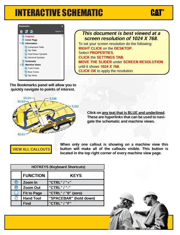
– Schematic
– Machines Views
– Machine Component Loaation
– Pilot Filter
– Control Valve
– Main Pump
Specifications 308D Excavator Machine System
– Accumulator (Pilot)
– Air Conditioner Lines
– Auxiliary Hydraulic Lines – Long Stick
– Auxiliary Hydraulic Lines – Medium Pressure Long Stick
– Auxiliary Hydraulic Lines – Medium Pressure Medium Stick
– Auxiliary Hydraulic Lines – Medium Stick
– Blade Cylinder Lines
– Blade Lift Cylinder
– Blade Mounting
– Boom – 3.39 m (11.1 ft)
– Boom – 3.7 m (12 ft)
– Boom Cylinder
– Boom Cylinder
– Boom Cylinder – Variable Angle
– Boom Cylinder Lines
– Boom Cylinder Lines
– Boom Lines
– Boom Lines
– Bucket Cylinder
– Bucket Cylinder
– Bucket Cylinder Lines
– Bucket Linkage
– Cab
– Check Valve (Hydraulic Oil Cooler Bypass)
– Control Manifold (Pilot Oil)
– Counterweight
– Cylinder (Thumb)
– Engine Mounting
– Fasteners
– Final Drive
– Front Idler
– Front Lines
– Front Lines
– Fuel Lines
– Fuel Lines
– Fuel Tank
– Fuel Tank
– Handle Control (Travel)
– Heater and Air Conditioner Mounting
– Hydraulic Tank and Filter
– Hydraulic Tank Mounting
– Joystick Control
– Joystick Control
– Joystick Control
– Main Hydraulic Pump
– Main Hydraulic Pump Mounting
– Operator Monitor
– Pilot Lines
– Pilot Valve (Joystick)
– Pilot Valve (Travel)
– Pump Coupling
– Recoil Spring
– Refrigerant Compressor Mounting
– Sprocket
– Stick – Long 2.21 m (7.3 ft)
– Stick – Medium 1.67 m (5.5 ft)
– Stick Cylinder
– Stick Cylinder
– Stick Cylinder Lines
– Stick Lines – Long
– Stick Lines – Medium
– Swing Boom Cylinder
– Swing Drive
– Swing Gear and Bearing
– Swivel
– Swivel
– Track
– Track Adjuster
– Track Carrier Roller
– Track Roller (Center Flange)
– Track Roller (Single Flange)
– Track Roller Mounting
– Track Roller Mounting
– Track Roller Mounting
– Travel Motor Guard
– Travel Motor Lines
– Travel Motor Lines
– Upper Frame
– Upper Frame – Swing
– Wiring (Battery)
– Wiring (Battery)
Systems Operation 308D CR Excavator Hydraulic System
– Accumulator (Pilot)
– Blade Hydraulic System
– Boom Hydraulic System
– Bucket Hydraulic System
– Bypass Valve (Return) – Bypass Check Valve
– Check Valve (Load)
– Check Valve (Return Makeup) – Slow Return Check Valve
– Control Valve (Boom Lowering)
– Control Valve (Stick Lowering)
– Cylinders (Boom, Stick and Bucket)
– Displacement Change Valve
– Final Drive
– Gear Pump (Pilot)
– General Information
– Hydraulic Filter (Pilot)
– Hydraulic Oil Cooler
– Hydraulic Tank and Filter
– Main Control Valve
– Main Hydraulic Pump
– Main Hydraulic System
– Medium Pressure Hydraulic System
– Oil Makeup (Swing System)
– Oil Makeup (Travel System)
– One-Way Flow Hydraulic System
– Pilot Hydraulic System
– Pilot Valve (Joystick)
– Pilot Valve (Swing Parking Brake)
– Pilot Valve (Travel)
– Proportional Priority Pressure Compensation System – Metered
– Pump Control (Main Hydraulic)
– Relief Valve (Cushion Crossover) – Anti-Reaction Valve
– Relief Valve (Line)
– Relief Valve (Main)
– Relief Valve (Pilot)
– Relief Valve (Swing)
– Return Hydraulic System
– Solenoid Valve (Hydraulic Lockout)
– Stick Hydraulic System
– Swing Boom Hydraulic System
– Swing Drive
– Swing Hydraulic System
– Swing Motor
– Swivel
– Travel Counterbalance Valve
– Travel Hydraulic System
– Travel Motor
– Travel Parking Brake
– Two-Way Flow Hydraulic System
Systems Operation D Series Excavator Monitoring System
– Input Components
– Performance Mode
– Service Mode
– Maintenance Mode
– Password Change Mode
– Diagnostic Mode
– ECM Information Mode
– Status Mode
– Calibration Mode
– Device Test Mode
– Override Mode
– Output Components
– Configuration Mode
– Tool Program Mode
– System Schematic
– Data Link
– Prestart Monitoring Function
– Warning Operation
– Menu Outline
– Password Entry
– Setting Mode
– Maintenance Information Mode
– General Information
Systems Operation EquipmentManager Dealer Administrator Manual
– Active Fleet
– Administration
– Asset Watch
– Enable Program
– Equipment Usage
– Fault Codes
– Fuel Results
– General Information
– Getting Started
– Health Watch
– Maintenance Watch
– Major Repair
– Manage Equipment Groups
– Manage Event Tracking
– Manage Hardware
– Manage Major Repair Tracking
– Manage Planned Maintenance
– Manage Time Fence and Geographic Fence
– Manage Users
– Operation and Maintenance Manual
– Planned Maintenance
– Preference Detail
– Preferences
– Product Link Installation
– Product Monitoring
– Product Usage
– Reports
– Setup Subscriptions
– Time Fence and Geographic Fence
– Upload Data
– Verify Machine Records and Ownership
Systems Operation EquipmentManager User Guide
– Getting Started
– Manage Major Repair Tracking
– Manage Time Fence and Geographic Fence
– Manage Planned Maintenance
– Preferences
– Preference Detail
– Asset Watch
– Time Fence and Geographic Fence
– Maintenance Watch
– Planned Maintenance
– Major Repair
– Verify Machine Records and Ownership
– Health Watch
– Fuel Results
– Fault Codes
– Reports
– Product Usage
– Product Monitoring
– Operation and Maintenance Manual
– Equipment Usage
– Manage Users
– Product Link Installation
– Administration
– Manage Equipment Groups
– Manage Hardware
– Manage Event Tracking
– Upload Data
– General Information
Systems Operation Troubleshooting Testing and Adjusting Product Link – PL522 523
– System Components
– Reports and Messages Not Available
– Position Reports Not Available
– Reporting Interval Erratic
– Diagnostics and Events Not Available
– Operating Hours Discrepancy
– Event Code List
– Diagnostic Code List
– MID 161 – CID 0168 – FMI 00
– MID 161 – CID 0168 – FMI 01
– MID 161 – CID 0254 – FMI 04
– Installation Parameters Configure
– MID 161 – CID 0254 – FMI 12
– MID 161 – CID 1250 – FMI 09
– MID 161 – CID 1251 – FMI 03
– MID 161 – CID 1888 – FMI 14
– MID 161 – CID 3766- FMI 14
– Electronic Control Module (ECM) – Flash Program
– Electronic Control Module (ECM) – Replace
– Electrical Connector – Inspect
– Wiring Harness (Open Circuit) – Test
– Wiring Harness (Short Circuit) – Test
– Configuration
– Specifications
– System Schematic
– Spare Input Configure
– Commands
– General Information
– Service Tools
– Diagnostic Capabilities
– Electronic Service Tool Does Not Communicate with ECM
– System Overview
Systems Operation Troubleshooting Testing and Adjusting Product Link 121S 300
– System Components
– Service Tools
– Diagnostic Capabilities
– Electronic Service Tool Does Not Communicate with ECM
– ECM Does Not Communicate with User Interface
– Position Reports Not Available
– Reporting Interval Erratic
– Diagnostics and Events Not Available
– Operating Hours Discrepancy
– Event Code List
– Diagnostic Code List
– Spare Inputs
– MID 122 – CID 0168 – FMI 00
– MID 122 – CID 0168 – FMI 01
– MID 122 – CID 0254 – FMI 04
– MID 122 – CID 0254 – FMI 12
– MID 122 – CID 0269 – FMI 03
– MID 122 – CID 0269 – FMI 04
– MID 122 – CID 1250 – FMI 09
– MID 122 – CID 1251 – FMI 03
– Electronic Control Module (ECM) – Flash Program
– Electronic Control Module (ECM) – Replace
– Configuration
– Electrical Connector – Inspect
– Wiring Harness (Open Circuit) – Test
– Wiring Harness (Short Circuit) – Test
– Specifications
– System Schematic
– Installation Parameters Configure
– Report Parameters Configure
– Wireless Service Configure
– Spare Input Configure
– Commands
– General Information
– System Overview
Testing and Adjusting 308D CR Mini Hydraulic Excavator Hydraulic System
– Accumulator (Pilot) – Test and Charge
– Cylinder Drift – Check – Blade (If Equipped)
– Cylinder Drift – Check – Empty Bucket
– Cylinder Drift – Check – Loaded Bucket
– Cylinder Speed – Check
– Cylinder Speed – Check
– Cylinder Speed – Check – Blade (If Equipped)
– Cylinder Speed – Check – Boom Swing
– Engine Performance – Test – Engine Speed
– Event Codes
– Gear Pump (Pilot) – Test
– General Testing and Adjusting Information
– Hydraulic System Air – Purge – Resonator Line
– Hydraulic System Pressure – Release
– Joystick Control – Calibrate – Slide Control
– Machine Drift on a Slope – Check
– Machine Tool Control System – Select
– Main Hydraulic Pump Air – Purge
– Main Pump (Flow) – Test
– Operational Checks
– Process for Setting Up the Work Tool
– Pump Control (Output Flow) – Adjust
– Relief Valve (Blade) – Test and Adjust – If Equipped
– Relief Valve (Blade) – Test and Adjust – If Equipped
– Relief Valve (Line) – Test and Adjust
– Relief Valve (Line) – Test and Adjust – Boom and Stick
– Relief Valve (Main) – Test and Adjust
– Relief Valve (Pilot) – Test and Adjust
– Relief Valve (Swing) – Test and Adjust
– Solenoid Valve (Proportional Reducing) – Calibrate
– Specifications
– Specifications
– Swing Motor – Test – Measurement of Case Drain Oil
– Swing Speed and Overswing on Level Ground – Check
– Swing Speed and Overswing on Level Ground – Check
– Swing Speed and Swing Drift on a Slope – Check
– Swing Speed and Swing Drift on a Slope – Check
– Travel Motor – Test – Measurement of Case Drain Oil
– Travel on Level Ground – Test
– Travel on Level Ground – Test – Optional Test
– Visual Inspection
– Work Tool – Select
– Work Tool Parameter – Default Values
– Work Tool Parameter – Program
Service manual Caterpillar 308D Mini Hydraulic Excavator with 4M40 Engine | FYC00001-UP
29,99 $
Format: PDF
Type: Service Manual
Pages: 3904
Size: 184 Mb
No.: FYC00001-UP
-
 Service manual Caterpillar 352F Excavators with C13 Engine | YEG00001-UP
29,99 $
ADD TO CART
Service manual Caterpillar 352F Excavators with C13 Engine | YEG00001-UP
29,99 $
ADD TO CART -
 Schematic Caterpillar 950L and 962L Wheel Loader Hydraulic System | M0099670-00
4,99 $
ADD TO CART
Schematic Caterpillar 950L and 962L Wheel Loader Hydraulic System | M0099670-00
4,99 $
ADD TO CART -
 Schematic Caterpillar 966M XE and 972M XE Wheel Loader Electrical System | UENR3832-05
9,99 $
ADD TO CART
Schematic Caterpillar 966M XE and 972M XE Wheel Loader Electrical System | UENR3832-05
9,99 $
ADD TO CART -
 Schematic Caterpillar D6 XE Bulldozer Electrical System | M0101049-07
9,99 $
ADD TO CART
Schematic Caterpillar D6 XE Bulldozer Electrical System | M0101049-07
9,99 $
ADD TO CART -
 Service manual Caterpillar 340F Excavators with C9.3 Engine | XBD00001-UP
29,99 $
ADD TO CART
Service manual Caterpillar 340F Excavators with C9.3 Engine | XBD00001-UP
29,99 $
ADD TO CART -
 Service manual Caterpillar 390F L Excavator with C18 Engine | HJD00001-UP
29,99 $
ADD TO CART
Service manual Caterpillar 390F L Excavator with C18 Engine | HJD00001-UP
29,99 $
ADD TO CART
Reviews
There are no reviews yet.