415F2, 415F2 IL, 416F2, 420F2, 420F2 IT, 420F2 ST, 430F2 IT and 430F2 ST Backhoe Loaders Transmission (Standard Shift)
– Flexible Coupling Drive
– Flexible Coupling Drive
– General Information
– Governor Control
– Governor Control
– Governor Control
– Governor Control
– Power Train Troubleshooting
– Pressure Taps – Standard Shift
– Pump Drive
– Pump Drive – Mounting
– Pump Lines
– Pump Lines
– Solenoid Valve (Standard Shift)
– Solenoid Valve (Standard Shift)
– Steering Lines
– Steering Lines
– Torque Converter
– Torque Converter
– Transmission (All-Wheel Drive)
– Transmission (Standard Shift)
– Transmission (Standard Shift)
– Transmission (Standard Shift)
– Transmission (Two-Wheel Drive)
– Transmission and Torque Converter – Test
– Transmission Case
– Transmission Case
– Transmission Case
– Transmission Case
– Transmission Control
– Transmission Control
– Transmission Control
– Transmission Hydraulic System
– Transmission Oil Pump
– Transmission Oil Pump
– Transmission Oil Pump
Disassembly and Assembly 415F2 Industrial Loader Machine Systems
– 3-Point Hitch – Remove and Install
– Air Conditioner and Heater – Remove and Install
– Bank Valve (3-Point Hitch) – Remove and Install
– Bank Valve (Loader) – Remove and Install
– Blade – Remove and Install
– Bucket – Remove and Install
– Bucket Positioner Control – Remove and Install – Single Tilt
– Cab – Install
– Cab – Remove
– Canopy – Remove and Install
– Counterweight – Remove and Install – Front
– Fuel Tank – Remove and Install
– Hitch Link (3-Point Hitch) – Remove and Install
– Hydraulic Tank – Remove and Install
– Lift Arm (3-Point Hitch) – Remove and Install
– Lift Arms – Remove and Install – Single Tilt
– Lift Cylinder (3-Point Hitch) – Remove and Install
– Lift Cylinder – Remove and Install – Single Tilt
– Link Arm (3-Point Hitch) – Remove and Install
– Pilot Valve (3-Point Hitch) – Remove and Install
– Piston Pump (Main Hydraulic) – Remove and Install
– Pitch Cylinder (3-Point Hitch) – Remove and Install
– Plates (3-Point Hitch) – Remove and Install
– Refrigerant Accumulator – Remove and Install
– Ride Control Accumulator – Remove and Install
– Scarifier – Remove and Install
– Scarifier Cylinder – Remove and Install
– Seat – Remove and Install
– Steering Metering Pump – Remove and Install
– Steering Wheel – Remove and Install
– System Pressure – Release
– Tilt Cylinder (3-Point Hitch) – Remove and Install
– Tilt Cylinder – Remove and Install – Single Tilt
– Window Wiper and Wiper Motor (Front) – Remove and Install
– Window Wiper and Wiper Motor (Rear) – Remove and Install
Disassembly and Assembly 415F2 Industrial Loader Power Train
– Axle Housing (Differential and Bevel Gear) (Front) –
– Axle Housing (Differential and Bevel Gear) (Front) – Assemble
– Axle Housing (Service Brakes, Differential and Bevel Gear) –
– Axle Housing (Service Brakes, Differential and Bevel Gear) –
– Axle Housing and Flange – Assemble
– Axle Housing and Flange – Disassemble
– Axle Housing and Flange – Install
– Axle Housing and Flange – Remove
– Axle Housing, Axle Shaft, and Wheel Flange – Assemble – Rear
– Axle Housing, Axle Shaft, and Wheel Flange – Disassemble –
– Axle Housing, Axle Shaft, and Wheel Flange – Install – Rear Axle
– Axle Housing, Axle Shaft, and Wheel Flange – Remove – Rear
– Axle Shaft – Remove and Install
– Drive and Steering Axle (Front) – Install
– Drive and Steering Axle (Front) – Remove
– Drive Shaft (Front) – Remove and Install
– Drive Shaft (Rear) – Remove and Install
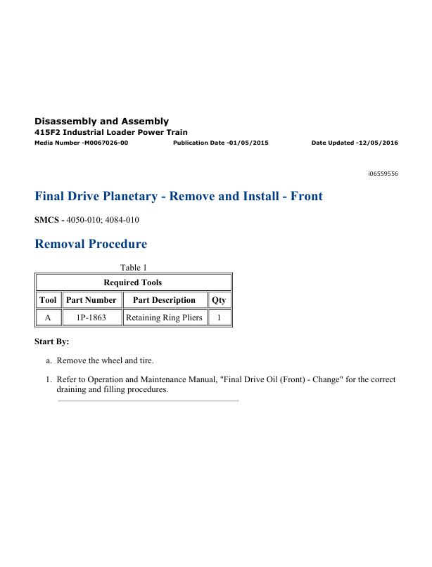
– Final Drive Planetary – Remove and Install
– Final Drive Planetary – Remove and Install – Front
– Rear Axle – Install
– Rear Axle – Remove
– Solenoid Valve (Transmission) – Remove and Install
– Steering Cylinder (Front) – Remove and Install
– System Pressure – Release
– Tie Rod (Steering)(Front) – Remove and Install
– Tire and Rim (Front) – Remove and Install
– Tire and Rim (Rear) – Remove and Install
– Transmission (Direct Drive) – Assemble
– Transmission (Direct Drive) – Disassemble
– Transmission (Direct Drive) – Install
– Transmission (Direct Drive) – Remove
Disassembly and Assembly C3.4B Engines for Caterpillar Built Machines
– Accessory Drive – Remove and Install
– Alternator – Install
– Alternator – Remove
– Alternator Belt – Remove and Install
– Balancer – Install
– Balancer – Remove
– Bearing Clearance – Check
– Camshaft – Remove and Install
– Camshaft Bearings – Remove and Install
– Camshaft Gear – Remove and Install
– Camshaft Position Sensor – Remove and Install
– Connecting Rod Bearings – Install – Connecting rods in position
– Connecting Rod Bearings – Remove – Connecting rods in
– Coolant Temperature Sensor – Remove and Install
– Crankcase Breather – Install
– Crankcase Breather – Remove
– Crankshaft – Install
– Crankshaft – Remove
– Crankshaft Front Seal – Remove and Install
– Crankshaft Main Bearings – Remove and Install
– Crankshaft Position Sensor – Remove and Install
– Crankshaft Pulley – Remove and Install
– Crankshaft Rear Seal – Remove and Install
– Crankshaft Timing Ring – Remove and Install
– Cylinder Head – Install
– Cylinder Head – Remove
– Diesel Particulate Filter – Install – Through Flow Diesel
– Diesel Particulate Filter – Install – Wall Flow Diesel Particulate
– Diesel Particulate Filter – Remove – Through Flow Diesel
– Diesel Particulate Filter – Remove – Wall Flow Diesel
– Electric Starting Motor – Remove and Install
– Electronic Unit Injector – Install
– Electronic Unit Injector – Remove
– Engine Lifting Bracket – Install
– Engine Lifting Bracket – Remove
– Engine Oil Cooler – Install
– Engine Oil Cooler – Remove
– Engine Oil Filter Base – Remove and Install
– Engine Oil Pan – Remove and Install – Cast Iron Engine Oil Pan
– Engine Oil Pan – Remove and Install – Pressed Steel Oil Pan
– Engine Oil Pressure Switch – Remove and Install
– Engine Oil Pump – Install
– Engine Oil Pump – Remove
– Engine Oil Relief Valve – Remove and Install
– Exhaust Cooler (NRS) – Remove and Install
– Exhaust Gas Recirculation Valve – Remove and Install
– Exhaust Manifold – Remove and Install
– Fan – Remove and Install
– Fan Drive – Remove and Install
– Flexible Exhaust Pipe – Remove and Install
– Flow Control Valve – Remove and Install
– Flywheel – Install
– Flywheel – Remove
– Flywheel Housing – Remove and Install – Non-Stressed Cylinder
– Flywheel Housing – Remove and Install – Stressed Cylinder
– Front Cover – Remove and Install
– Fuel Filter Base – Remove and Install
– Fuel Injection Lines – Install
– Fuel Injection Lines – Remove
– Fuel Injection Pump – Install
– Fuel Injection Pump – Remove
– Fuel Injection Pump Gear – Install
– Fuel Injection Pump Gear – Remove
– Fuel Manifold (Rail) – Remove and Install
– Fuel Priming Pump – Remove and Install
– Fuel Temperature Sensor – Remove and Install
– Glow Plugs – Remove and Install
– Housing (Front) – Install
– Housing (Front) – Remove
– Idler Gear – Install
– Idler Gear – Remove
– Idler Pulley – Remove and Install
– Inlet and Exhaust Valve Guides – Remove and Install
– Inlet and Exhaust Valve Springs – Remove and Install
– Inlet and Exhaust Valves – Remove and Install
– Inlet Manifold – Remove and Install
– Inlet Manifold Pressure Sensor – Remove and Install
– Inlet Manifold Temperature Sensor – Remove and Install
– Lifter Group – Remove and Install
– Oxygen Sensor – Remove and Install – Catalytic Converter
– Piston Cooling Jets – Remove and Install
– Pistons and Connecting Rods – Assemble
– Pistons and Connecting Rods – Disassemble
– Pistons and Connecting Rods – Install
– Pistons and Connecting Rods – Remove
– Power Take-Off Drive – Remove and Install
– Pressure Sensor (DPF) – Remove and Install
– Pressure Sensor (Exhaust Back Pressure) – Remove and Install
– Rocker Shaft – Assemble
– Rocker Shaft – Disassemble
– Rocker Shaft and Pushrod – Install
– Rocker Shaft and Pushrod – Remove
– Support and Mounting (CEM) – Remove and Install – Option 1
– Support and Mounting (CEM) – Remove and Install – Option 2
– Support and Mounting (CEM) – Remove and Install – Option 3
– Temperature Sensor (DPF) – Remove and Install
– Temperature Sensor (Exhaust) – Remove and Install
– Throttle Valve (Intake Air) – Remove and Install – Rear Facing
– Throttle Valve (Intake Air) – Remove and Install – Side Facing
– Turbocharger – Install – Side Mounted Turbochargers
– Turbocharger – Install – Top Mounted Turbochargers
– Turbocharger – Remove – Side Mounted Turbochargers
– Turbocharger – Remove – Top Mounted Turbochargers
– Valve Mechanism Cover – Remove and Install
– Wastegate Solenoid – Remove and Install
– Water Pump – Install
– Water Pump – Remove
– Water Separator and Fuel Filter (Primary) – Remove and
– Water Temperature Regulator – Remove and Install
F2 Series Backhoe Loaders Monitoring System
– Connector Contact Description
– Data Link
– Determining Diagnostic Trouble Codes
– Diagnostic Capabilities
– Diagnostic Trouble Codes
– Display Module
– Electrical Connector – Inspect
– Event Codes
– General Information
– Menu Navigation
– Menus
– Module – Flash Program
– Module – Replace
– Monitoring System
– Sensor Signal (Analog, Passive) – Test
– Service Menu
– Service Tools
– Settings Menu
– System Schematic
– Totals Menu
– Warning Operation
– Wiring Harness (Open Circuit) – Test
– Wiring Harness (Short Circuit) – Test
Schematic Caterpillar 415F2 Industrial Loader Hydraulic System
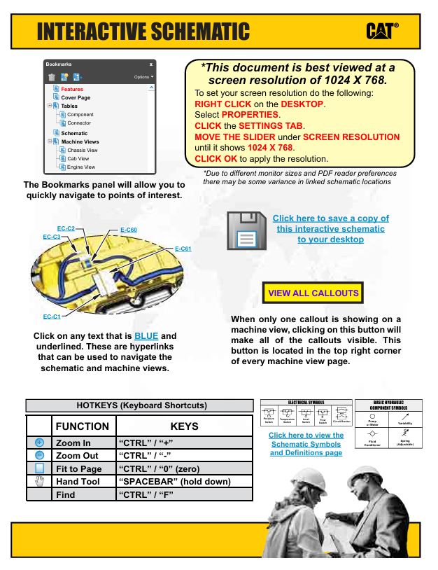
– Features
– Cover page
– Tables
– Components
– Taps
– Schematic
– Machine Views
– Top View
– Front Left
Schematic Caterpillar 415F2, 427F2 Backhoe Loader and 415F2 Industrial Loader Electrical System
– Features
– Cover page
– Tables
– Components
– Cab and Chassis
– Engine and Attachments
– Connectors
– Cab and Chassis
– Engine and Attachments
– Schematic
– Cab and Chassis
– Engine and Attachments
– Machine Views
– Cab and Chassis
– Transmission
– Side Console
– RH Chassis
– Return To Dig
– Headliner
– Front Dash
– Cab Front
– RH Cab/Chassis
– Engine and Attachments
– Side Console / Headliner
– RH Engine
– Rear End Configurations
– Rear Chassis
– Load Check Disable Wiring
– LH Engine
– HVAC
– Headliner
– Front Dash
– Differential Lock
Schematic Caterpillar 415F2, 427F2 Backhoe Loader and 415F2 Industrial Loader Electrical System
– Feature
– Cover Page
– Information
– Component Location
– Volume 1 of 2 – Cab And Chassis
– Volume 2 of 2 – Engine And Additional Attachments
– Connector Location
– Volume 1 of 2 – Cab And Chassis
– Volume 2 of 2 – Engine And Additional Attachments
– Schematics
– Volume 1 of 2 – Cab And Chassis
– Volume 2 of 2 – Engine And Additional Attachments
– Machine Views
– Volume 1 of 2 – Cab And Chassis
– Cab Front View
– Front Dash View
– Headliner View
– Return To DIG Switch Wiring
– RH Cab/Chassis View
– RH Chassis View
– Side Console View
– Transmission
– Volume 2 of 2 – Engine And Additional Attachments
– Cab Rightside View
– Differential Lock View
– Headliner View
– HVAC View
– LH Engine View
– Load Check Disable Wiring
– Rear Chassis View
– Rear End Configurations
– RH Engine View
– Side Console/Headliner View
Specifications 415F2 Backhoe Loaders Axles, Differential, and Brakes
– Axle (Front)
– Axle (Rear)
– Drive Shaft
– Drive Shaft
– Parking Brake Control
– Service Brake Control
– Wheel and Tire (Front)
– Wheel and Tire (Front)
– Wheel and Tire (Rear) Wheel and Tire (Rear)
Specifications 415F2 Backhoe Loaders Hydraulic and Steering System
– Bank Valve (Three)(Mechanically Operated)
– Bucket Positioner and Lift Kickout
– Check Valve
– Control Valve (Lift)(Mechanically Operated)
– Control Valve (Tilt)(Mechanically Operated)
– Hydraulic Accumulator (Pilot Oil)
– Hydraulic Hand Control
– Hydraulic Hand Control (Loader) (Mechanically Operated)
– Hydraulic Tank and Mounting
– Lift Arm
– Lift Cylinder
– Lift Cylinder Brace
– Lines (Hydraulic)
– Lines (Hydraulic) – Lift and Tilt Cylinder
– Lines (Hydraulic) – Return
– Multipurpose Bucket Cylinder
– Oil Filter (Hydraulic)
– Oil Filter (Hydraulic) – Mounting
– Piston Pump (Work Tool and Steering)
– Pump Control Valve (Pressure and Flow Compensator)
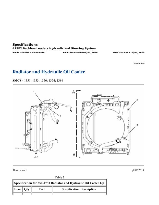
– Radiator and Hydraulic Oil Cooler
– Radiator and Hydraulic Oil Cooler
– Relief Valve
– Service Brake Control
– Steering Control Group
– Tilt Cylinder
– Tilt Cylinder
Specifications C3.4B Engines For Caterpillar Built Machines
– Alternator
– Boost Pressure Sensor – If equipped
– Camshaft
– Camshaft Bearings
– Connecting Rod
– Connecting Rod Bearing Journal
– Coolant Temperature Sensor
– Crankcase Breather
– Crankshaft
– Crankshaft Pulley
– Cylinder Block
– Cylinder Head
– Cylinder Head Valves
– Electronic Control Module
– Engine Design
– Engine Lifting Bracket
– Engine Oil Cooler
– Engine Oil Filter Base
– Engine Oil Pan – Pressed Steel Oil Pan
– Engine Oil Pressure
– Engine Oil Pump
– Exhaust Cooler (NRS)
– Exhaust Gas Valve (NRS)
– Exhaust Manifold
– Fan Drive
– Flywheel
– Flywheel Housing
– Front Housing and Covers
– Fuel Filter Base – Primary Fuel Filter Base
– Fuel Filter Base – Secondary Fuel Filter Base
– Fuel Injection Lines
– Fuel Injection Nozzles
– Fuel Injection Pump
– Fuel Manifold (Rail)
– Gear Group (Front)
– Glow Plugs
– Inlet Manifold Temperature and Pressure Sensor – If equipped
– Inlet Manifold Temperature Sensor – If equipped
– Lifter Group
– Main Bearing Journal
– Oxygen Sensor
– Piston and Rings
– Piston Cooling Jet
– Pressure Sensor (NOx Reduction System)
– Rocker Shaft
– Speed/Timing Sensor
– Starter Motor
– Temperature Sensor (DOC Inlet)
– Temperature Sensor (DPF Inlet)
– Temperature Sensor (NOx Reduction System)
– Turbocharger
– Valve Mechanism Cover
– Water Pump
– Water Temperature Regulator and Housing
Systems Operation, Testing and Adjusting 415F2 IL Backhoe Loader Axles, Differentials and Brakes
– Axle (Front)
– Axle (Front) – Adjust
– Axle (Rear)
– Axle Housing and Bearing Preload – Adjust
– Brake System Air – Purge
– Differential – Standard
– Differential Backlash and Bearings – Adjust
– Differential Pinion Bearing – Adjust
– Parking Brake Control – Adjust
– Service Brake Control
– Service Brake Control – Adjust
Systems Operation, Testing and Adjusting 415F2 IL Backhoe Loader Hydraulic and Steering Systems
– Bank Valve (3-Point Hitch)
– Bank Valve (Loader) – Single Tilt – Direct Operating
– Control Valve (Auxiliary)(Loader) – Mechanically Operated
– Control Valve (Tilt) – Mechanically Operated
– General Information (Hydraulic System)
– General Information (Steering)
– Hydraulic Oil Contamination – Test
– Hydraulic Pump – Test and Adjust
– Hydraulic Tank and Filter
– Pilot System Pressure – Test
– Piston Pump (Work Tool and Steering)
– Priority Valve – Inlet Manifold of the Loader
– Relief Valve (Line) – Test and Adjust
– Relief Valve (Loader) – Test and Adjust
– Ride Control – Test
– Ride Control Accumulator – Test and Charge
– Ride Control System
– System Pressure – Release
– Worksheets – Troubleshoot
Systems Operation, Testing and Adjusting C3.4B Engines for Caterpillar Built Machines
– Air in Fuel – Test
– Air Inlet and Exhaust System
– Air Inlet and Exhaust System – Inspect
– Alternator – Test
– Basic Engine
– Battery – Test
– Charging System – Test
– Clean Emissions Module
– Cleanliness of Fuel System Components
– Compression – Test
– Connecting Rod – Inspect
– Cooling System
– Cooling System – Check
– Cooling System – Inspect
– Cooling System – Test
– Crankshaft Pulley – Check
– Cylinder Block – Inspect
– Cylinder Head – Inspect
– Diesel Particulate Filter – Clean
– Electric Starting System – Test
– Electrical System
– Electronic Control System
– Engine Oil Cooler – Inspect
– Engine Oil Pressure – Test
– Engine Oil Pump – Inspect
– Engine Valve Lash – Inspect
– Excessive Bearing Wear – Inspect
– Excessive Engine Oil Consumption – Inspect
– Exhaust Cooler (NRS) – Test
– Finding Top Center Position for No. 1 Piston
– Flywheel – Inspect
– Flywheel Housing – Inspect
– Fuel Injection
– Fuel Injection Timing – Check
– Fuel Quality – Test
– Fuel System – Inspect
– Fuel System – Prime
– Fuel System Pressure – Test
– Gear Group (Front) – Time
– Gear Group – Inspect
– Glossary of Electronic Control Terms
– Increased Engine Oil Temperature – Inspect
– Introduction
– Lubrication System
– Piston Height – Inspect
– Piston Ring Groove – Inspect
– Position the Valve Mechanism Before Maintenance Procedures
– Power Sources
– Turbocharger – Inspect
– V-Belt – Test
– Valve Depth – Inspect
– Valve Guide – Inspect
– Water Pump – Inspect
– Water Temperature Regulator – Test
Troubleshooting C3.4B Engines
– Acceleration Is Poor or Throttle Response Is Poor
– Alternator Problem – Charging Problem and/or Noisy
– Battery Problem
– Component Location
– Configuration Parameters
– Coolant Contains Oil
– Coolant Level Is Low
– Coolant Temperature Is High
– Crankcase Breather Ejects Oil
– Cylinder Is Noisy
– Data Link – Test
– Diagnostic Capabilities
– Diagnostic Trouble Codes
– Diesel Particulate Filter Active Regeneration Occurrence Is
– Diesel Particulate Filter Active Regeneration Was Interrupted
– Diesel Particulate Filter Collects Excessive Soot
– Diesel Particulate Filter Has Differential Pressure Problem
– Diesel Particulate Filter Regeneration
– Diesel Particulate Filter Temperature Is Low
– ECM – Replace
– ECM Memory – Test
– ECM Software – Install
– Electrical Connectors
– Electrical Connectors – Inspect
– Electrical Power Supply – Test
– Electronic Service Tool Does Not Communicate
– Electronic Service Tools
– Engine Cranks but Does Not Start
– Engine Does Not Crank
– Engine Has Early Wear
– Engine Has Mechanical Noise (Knock)
– Engine Misfires, Runs Rough or Is Unstable
– Engine Monitoring System
– Engine Overspeeds
– Engine Shutdown Occurs Intermittently
– Engine Stalls at Low RPM
– Engine Top Speed Is Not Obtained
– Engine Vibration Is Excessive
– Exhaust Has Excessive Black Smoke
– Exhaust Has Excessive White Smoke
– Exhaust System Contains Coolant
– Exhaust System Contains Oil
– Fuel Consumption Is Excessive
– Fuel Contains Water
– Fuel Rail Pressure Problem
– Fuel Temperature Is High
– General Information
– Glow Plug Starting Aid – Test
– Idle Validation – Test
– Indicator Lamp – Test
– Injector Code – Calibrate
– Injector Data Incorrect – Test
– Injector Solenoid – Test
– Inlet Air Is Restricted
– Intake Manifold Air Pressure Is High
– Intake Manifold Air Pressure Is Low
– Intake Manifold Air Temperature Is High
– Mode Selection – Test
– Motorized Valve – Test
– NRS Mass Flow Rate Problem
– Oil Consumption Is Excessive
– Oil Contains Coolant
– Oil Contains Fuel
– Oil Pressure Is Low
– Oxygen Level – Test
– Power Is Intermittently Low or Power Cutout Is Intermittent
– Power Take-Off – Test
– Relay – Test – ECM Main Relay
– Relay – Test – Start Relay
– Sensor Signal (Analog, Active) – Test
– Sensor Signal (Analog, Active) – Test – Exhaust Gas Pressure
– Sensor Signal (Analog, Passive) – Test
– Sensor Supply – Test
– Service Information Report
– Service Tool Features
– Solenoid Valve – Test
– Speed Control – Test
– Speed/Timing – Test
– Switch Circuits – Test – Air Filter Restriction Switch
– Switch Circuits – Test – Engine Oil Pressure Switch
– Switch Circuits – Test – Throttle Switch
– System Overview
– Valve Lash Is Excessive
– Valve Position – Test
– Water in Fuel – Test
– Welding Precaution
Service manual Caterpillar 415F2 IL Backhoe Loader with C3.4 Engine | PF400001-UP
29,99 $
Format: PDF
Type: Service Manual
Pages: 2230
Size: 133 Mb
No.: PF400001-UP
-
 Service manual Caterpillar 962M Wheel Loader with C7.1 Engine | RKH00001-UP
29,99 $
ADD TO CART
Service manual Caterpillar 962M Wheel Loader with C7.1 Engine | RKH00001-UP
29,99 $
ADD TO CART -
 Service manual Caterpillar DP20NDS Forklift Lift Truck
19,99 $
ADD TO CART
Service manual Caterpillar DP20NDS Forklift Lift Truck
19,99 $
ADD TO CART -
 Schematic Caterpillar 336E H (Hybrid) Excavator (Electrical System) | UENR5470-02
9,99 $
ADD TO CART
Schematic Caterpillar 336E H (Hybrid) Excavator (Electrical System) | UENR5470-02
9,99 $
ADD TO CART -
 Schematic Caterpillar 349E Excavator 349E MHPU & 349E HVG UHD MHPU | KENR9607-10
4,99 $
ADD TO CART
Schematic Caterpillar 349E Excavator 349E MHPU & 349E HVG UHD MHPU | KENR9607-10
4,99 $
ADD TO CART -
 Service manual Caterpillar 320 GC Excavator with C4.4 Engine | DKJ00001-UP
29,99 $
ADD TO CART
Service manual Caterpillar 320 GC Excavator with C4.4 Engine | DKJ00001-UP
29,99 $
ADD TO CART -
 Schematic Caterpillar 236D, 242D, 246D, 262D, 257D, 277D, 287D, 259D, 279D, 289D | UENR7456-06
9,99 $
ADD TO CART
Schematic Caterpillar 236D, 242D, 246D, 262D, 257D, 277D, 287D, 259D, 279D, 289D | UENR7456-06
9,99 $
ADD TO CART
Reviews
There are no reviews yet.