414E, 416E, 420E, 422E, 428E, 430E, 432E, 434E, 442E and 444E Backhoe Loaders Axles, Differential and Brakes
– Axle (Front)
– Axle (Front) – Adjust
– Axle (Rear)
– Axle Housing and Bearing Preload – Adjust
– Brake System Air – Purge
– Brake System Air – Purge
– Differential
– Differential
– Differential
– Differential Backlash and Bearings – Adjust
– Differential Lock – If Equipped
– Differential Pinion Bearing – Adjust
– Drive and Steering Axle (Front)
– Drive and Steering Axle (Front) – Adjust
– Drive and Steering Axle (Rear)
– Drive and Steering Axle (Rear) – Adjust
– Parking Brake Control
– Parking Brake Control – Adjust
– Service Brake Control
– Service Brake Control – Adjust
– Service Brake Control – Power Assist
414E, 416E, 420E, 422E, 428E, 430E, 432E, 434E, 442E and 444E Backhoe Loaders Machine Systems
– All Wheel Steer
– Axle and Differential
– Backup Alarm Always Off
– Backup Alarm Always On
– Brake System
– Calibration
– Charging System
– Connector Contact Description
– Connector Locations
– Data Link
– Diagnostic Capabilities
– Diagnostic Code List
– Electrical Connector – Inspect
– Electrical Input Components
– Electrical Output Components
– Electronic Control Module
– Electronic Control Module (ECM) – Configure
– Electronic Control Module (ECM) – Flash Program
– Electronic Control Module (ECM) – Replace
– Event Code List
– Features
– General Information
– General Information
– Hydraulic System
– Location of Electrical Components
– MID 039 – CID 0041 – FMI 03
– MID 039 – CID 0041 – FMI 04
– MID 039 – CID 0168 – FMI 03
– MID 039 – CID 0168 – FMI 04
– MID 039 – CID 0191 – FMI 02
– MID 039 – CID 0367 – FMI 04
– MID 039 – CID 0368 – FMI 03
– MID 039 – CID 0368 – FMI 04
– MID 039 – CID 0368 – FMI 04
– MID 039 – CID 0490 – FMI 03
– MID 039 – CID 0490 – FMI 04
– MID 039 – CID 0600 – FMI 03
– MID 039 – CID 0600 – FMI 04
– MID 039 – CID 0626 – FMI 02
– MID 039 – CID 0629 – FMI 04
– MID 039 – CID 0668 – FMI 02
– MID 039 – CID 0668 – FMI 09
– MID 039 – CID 0668 – FMI 12
– MID 039 – CID 0702 – FMI 02
– MID 039 – CID 1187 – FMI 03
– MID 039 – CID 1187 – FMI 04
– MID 039 – CID 1251 – FMI 03
– MID 039 – CID 1251 – FMI 08
– MID 039 – CID 1401 – FMI 03
– MID 039 – CID 1401 – FMI 03
– MID 039 – CID 1401 – FMI 05
– MID 039 – CID 1401 – FMI 05
– MID 039 – CID 1401 – FMI 06
– MID 039 – CID 1401 – FMI 06
– MID 039 – CID 1402 – FMI 03
– MID 039 – CID 1402 – FMI 03
– MID 039 – CID 1402 – FMI 05
– MID 039 – CID 1402 – FMI 05
– MID 039 – CID 1402 – FMI 06
– MID 039 – CID 1402 – FMI 06
– MID 039 – CID 1403 – FMI 03
– MID 039 – CID 1403 – FMI 05
– MID 039 – CID 1403 – FMI 06
– MID 039 – CID 1404 – FMI 03
– MID 039 – CID 1404 – FMI 05
– MID 039 – CID 1404 – FMI 06
– MID 039 – CID 1405 – FMI 03
– MID 039 – CID 1405 – FMI 05
– MID 039 – CID 1405 – FMI 06
– MID 039 – CID 1406 – FMI 03
– MID 039 – CID 1406 – FMI 05
– MID 039 – CID 1406 – FMI 06
– MID 039 – CID 1482 – FMI 03
– MID 039 – CID 1482 – FMI 04
– MID 039 – CID 1529 – FMI 02
– MID 039 – CID 1529 – FMI 04
– MID 039 – CID 1956 – FMI 02
– MID 039 – CID 1956 – FMI 03
– MID 039 – CID 1956 – FMI 04
– MID 039 – CID 1956 – FMI 08
– MID 039 – CID 1957 – FMI 02
– MID 039 – CID 1957 – FMI 03
– MID 039 – CID 1957 – FMI 04
– MID 039 – CID 1957 – FMI 08
– MID 039 – CID 1958 – FMI 02
– MID 039 – CID 1958 – FMI 03
– MID 039 – CID 1958 – FMI 04
– MID 039 – CID 1958 – FMI 08
– MID 039 – CID 1959 – FMI 02
– MID 039 – CID 1959 – FMI 03
– MID 039 – CID 1959 – FMI 04
– MID 039 – CID 1959 – FMI 08
– MID 039 – CID 2108 – FMI 02
– MID 039 – CID 2108 – FMI 03
– MID 039 – CID 2108 – FMI 04
– MID 039 – CID 2108 – FMI 08
– MID 039 – CID 2108 – FMI 13
– MID 039 – CID 2236 – FMI 02
– MID 039 – CID 2236 – FMI 03
– MID 039 – CID 2236 – FMI 05
– MID 039 – CID 2236 – FMI 06
– MID 039 – CID 2237 – FMI 02
– MID 039 – CID 2237 – FMI 03
– MID 039 – CID 2237 – FMI 05
– MID 039 – CID 2237 – FMI 06
– MID 039 – CID 2242 – FMI 02
– MID 039 – CID 2242 – FMI 03
– MID 039 – CID 2242 – FMI 05
– MID 039 – CID 2242 – FMI 06
– MID 039 – CID 2243 – FMI 02
– MID 039 – CID 2243 – FMI 03
– MID 039 – CID 2243 – FMI 05
– MID 039 – CID 2243 – FMI 06
– MID 039 – CID 2244 – FMI 02
– MID 039 – CID 2244 – FMI 03
– MID 039 – CID 2244 – FMI 05
– MID 039 – CID 2244 – FMI 06
– MID 039 – CID 2245 – FMI 02
– MID 039 – CID 2245 – FMI 03
– MID 039 – CID 2245 – FMI 05
– MID 039 – CID 2245 – FMI 06
– MID 039 – CID 2529 – FMI 02
– MID 039 – CID 2529 – FMI 03
– MID 039 – CID 2529 – FMI 04
– MID 039 – CID 2529 – FMI 08
– MID 039 – CID 2529 – FMI 13
– MID 039 – CID 2530 – FMI 02
– MID 039 – CID 2530 – FMI 03
– MID 039 – CID 2530 – FMI 04
– MID 039 – CID 2530 – FMI 08
– MID 039 – CID 2530 – FMI 13
– MID 039 – CID 2531 – FMI 02
– MID 039 – CID 2531 – FMI 03
– MID 039 – CID 2531 – FMI 04
– MID 039 – CID 2531 – FMI 08
– MID 039 – CID 2531 – FMI 13
– MID 053 – CID 0820 – FMI 07
– MID 053 – CID 1603 – FMI 02
– MID 053 – CID 1603 – FMI 09
– MID 053 – CID 1603 – FMI 12
– MID 053 – CID 2402 – FMI 02
– MID 053 – CID 2402 – FMI 09
– MID 053 – CID 2403 – FMI 02
– MID 053 – CID 2403 – FMI 09
– MID 053 – CID 2403 – FMI 13
– MID 053 – CID 2652 – FMI 05
– MID 053 – CID 2652 – FMI 06
– MID 053 – CID 2735 – FMI 03
– MID 053 – CID 2735 – FMI 04
– MID 053 – CID 2736 – FMI 03
– MID 053 – CID 2736 – FMI 04
– Operational Checks (All Wheel Steer)
– Operational Checks (Axle, Differential)
– Operational Checks (Brake System)
– Operational Checks (Hydraulic System)
– Operational Checks (Steering System)
– Operational Checks (Transmission)
– Power Supply Circuit of Electronic Control Module
– Service Tools
– Steering System
– Switch Circuits
– System Schematic
– Transmission – Autoshift
– Transmission – Standard Shift
– Using Advisor to Determine Diagnostic Codes
– Using Caterpillar Electronic Technician to Determine
– Wiring Harness (Open Circuit) – Test
– Wiring Harness (Short Circuit) – Test
414E, 416E, 420E, 422E, 428E, 430E, 432E, 434E, 442E and 444E Backhoe Loaders Transmission (Standard Shift)
– General Information
– Machine Preparation for Troubleshooting
– Operational Checks
– Power Train Troubleshooting
– Pressure Taps
– Solenoid Valve (Standard Shift)
– Solenoid Valve (Standard Shift)
– Solenoid Valve (Standard Shift)
– Torque Converter
– Torque Converter
– Transmission (All-Wheel Drive)
– Transmission (Standard Shift)
– Transmission (Standard Shift)
– Transmission (Standard Shift)
– Transmission (Standard Shift)
– Transmission (Standard Shift)
– Transmission (Standard Shift)
– Transmission (Standard Shift) – All Wheel Drive
– Transmission (Standard Shift) – All Wheel Drive
– Transmission (Two-Wheel Drive)
– Transmission and Torque Converter – Test
– Transmission Control
– Transmission Hydraulic System
– Visual Inspection
416E, 422E and 428E Backhoe Loaders Hydraulic and Steering System
– Bank Valve (Backhoe)
– Bank Valve (Backhoe)
– Bank Valve (Backhoe) – Mechanically Operated
– Bank Valve (Loader) – Single Tilt
– Bank Valve (Loader) – Single Tilt – Direct Operating
– Control Manifold
– Control Manifold (Sideshift) – If Equipped
– Control Valve (Auxiliary)
– Control Valve (Auxiliary) – Mechanically Operated
– Control Valve (Auxiliary)(Loader)
– Control Valve (Auxiliary)(Loader) – Mechanically Operated
– Control Valve (Boom)
– Control Valve (Bucket)
– Control Valve (Bucket) – Mechanically Operated
– Control Valve (Extendable Stick)
– Control Valve (Extendable Stick) – Mechanically Operated
– Control Valve (Lift)
– Control Valve (Lift) – Mechanically Operated
– Control Valve (Stabilizer)
– Control Valve (Stabilizer) – Mechanically Operated
– Control Valve (Stick)
– Control Valve (Stick) – Mechanically Operated
– Control Valve (Swing)
– Control Valve (Swing) – Mechanically Operated
– Control Valve (Tilt)
– Control Valve (Tilt) – Mechanically Operated
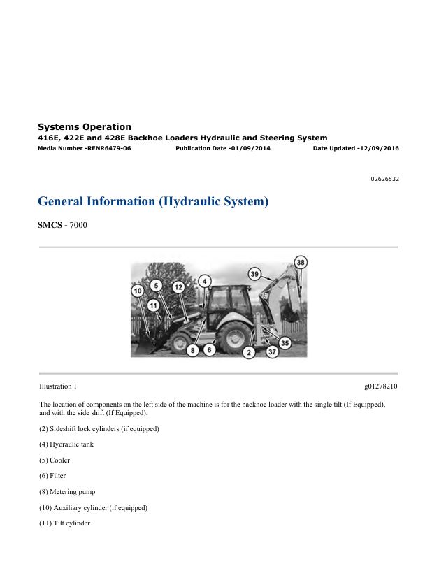
– General Information (Hydraulic System)
– General Information (Steering)
– Hydraulic Lockout Function
– Hydraulic Oil Contamination – Test
– Hydraulic Pump – Test and Adjust
– Hydraulic Pump – Test and Adjust
– Hydraulic Tank and Filter
– Load Check Valve
– Load Control Valve (Boom or Stick) – If Equipped
– Load Control Valve (Boom or Stick) – If Equipped
– Load Control Valve (Lift) – If Equipped
– Makeup and Relief Valve
– Metering Pump (Steering)
– Piston Pump (Work Tool and Steering)
– Pump Flow – Test
– Relief Valve (Line) – Test and Adjust
– Relief Valve (Steering Priority) – Test and Adjust
– Relief Valve (Steering) – Test
– Ride Control – Test
– Ride Control Accumulator – Test and Charge
– Ride Control System
– Sideshift Slide Lock Circuit – If Equipped
– Sideshift System – If Equipped
– Signal Resolver Network
– Signal Resolver Network – Check
– System Pressure – Release
– Worksheets – Troubleshoot
Air Conditioning and Heating R134a for All Caterpillar Machines
– Refrigerant Compressor
– System Capacities for Refrigerant (Off-Highway Trucks)
– General Information
– Identifying the Refrigerant
– Identifying the Air Conditioning System
– Identifying the Heating System
– Refrigerant Expansion Valve System
– Refrigerant Orifice Tube System
– Refrigerant Compressor
– Refrigerant Condenser
– Refrigerant Receiver-Dryer
– Refrigerant Compressor
– Refrigerant Expansion Valve
– In-line Refrigerant Dryer
– Refrigerant Orifice Tube Assembly
– Evaporator Coil
– Refrigerant Accumulator
– Refrigerant Compressor Protection System
– Temperature Control
– Pressure Switch (Refrigerant)
– Cab Pressurization and Filtration System
– Condensate Drainage System
– Refrigerant Compressor
– Service Intervals
– Glossary of Terms
– Required Tools
– Machine Preparation for Troubleshooting
– General Troubleshooting Information
– General Troubleshooting Information
– Visual Inspection (Troubleshooting)
– Air Conditioning System Troubleshooting
– Heating System Troubleshooting
– Automatic Temperature Control System (ECM Controlled)
– Refrigerant Compressor
– Troubleshooting Heating and Air Conditioning Control System
– Troubleshooting Heating and Air Conditioning Control System
– Automatic Temperature Control Panel Troubleshooting – 584
– Troubleshooting Condensate Drainage System
– Machine Preparation for Testing and Adjusting
– Air Conditioning Performance – Test
– Refrigerant Leakage – Test
– Manifold Gauge Set (Refrigerant) – Install
– Refrigerant Recovery
– Refrigerant System – Flush
– Refrigerant Compressor
– Refrigerant Oil – Test
– Refrigerant Compressor – Test
– Refrigerant System – Evacuate
– Refrigerant System – Charge
– Manifold Gauge Set (Refrigerant) – Remove
– Compressor Protection System – Test
– Electronic Heat Control – Test
– Heater Performance – Test
– Heating and Air Conditioning Service Publications
– General Information
– Refrigerant Compressor
– Machine Preparation for Disassembly and Assembly
– Air Conditioner Lines – Remove and Install
– Refrigerant Compressor – Remove and Install
– Refrigerant Accumulator – Remove and Install
– Refrigerant Expansion Valve – Remove and Install
– Refrigerant Receiver-Dryer – Remove and Install
– In-Line Refrigerant Dryer – Remove and Install
– Refrigerant Orifice Tube Assembly – Remove and Install
– Refrigerant Compressor
– System Capacities for Refrigerant (Motor Graders)
– System Capacities for Refrigerant (Off-Highway Trucks) –
– Refrigerant Compressor
Disassembly and Assembly 3054C Engines for Caterpillar Built Machines
– Fuel Injection Lines – Remove and Install
– Inlet and Exhaust Valves – Remove and Install
– Inlet and Exhaust Valve Guides – Remove and Install
– Inlet and Exhaust Valve Seat Inserts – Remove and Install
– Engine Oil Filter Base – Remove and Install
– Engine Oil Cooler – Remove
– Engine Oil Cooler – Install
– Engine Oil Relief Valve – Remove and Install – Engine without
– Engine Oil Pump – Remove – Engines Without a Balancer
– Engine Oil Pump – Install – Engines Without a Balancer
– Water Pump – Remove and Install
– Fuel Injection Nozzles – Remove
– Water Temperature Regulator – Remove and Install
– Flywheel – Remove
– Flywheel – Install
– Crankshaft Rear Seal – Remove
– Crankshaft Rear Seal – Install
– Crankshaft Wear Sleeve (Rear) – Remove
– Crankshaft Wear Sleeve (Rear) – Install
– Flywheel Housing – Remove and Install
– Crankshaft Pulley – Remove and Install
– Crankshaft Front Seal – Remove
– Fuel Injection Nozzles – Install
– Crankshaft Front Seal – Install
– Front Cover – Remove and Install
– Idler Gear – Remove and Install – Delphi DP210 Fuel Injection
– Housing (Front) – Remove
– Housing (Front) – Install
– Accessory Drive – Remove and Install
– Crankcase Breather – Remove and Install
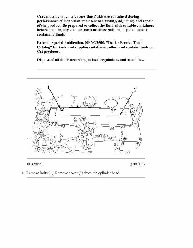
– Valve Mechanism Cover – Remove and Install
– Rocker Shaft and Pushrod – Remove
– Rocker Shaft – Disassemble
– Fuel Injection Pump – Remove – Delphi DP210
– Rocker Shaft – Assemble
– Rocker Shaft and Pushrod – Install
– Cylinder Head – Remove
– Cylinder Head – Install
– Lifter Group – Remove and Install
– Camshaft – Remove and Install
– Camshaft Bearings – Remove and Install
– Engine Oil Pan – Remove and Install
– Piston Cooling Jets – Remove and Install
– Pistons and Connecting Rods – Remove
– Fuel Injection Pump – Install – Delphi DP210
– Pistons and Connecting Rods – Disassemble
– Pistons and Connecting Rods – Assemble
– Pistons and Connecting Rods – Install
– Connecting Rod Bearings – Remove
– Connecting Rod Bearings – Install
– Crankshaft Main Bearings – Remove
– Crankshaft Main Bearings – Install
– Crankshaft – Remove
– Crankshaft – Install
– Crankshaft Gear – Remove and Install
– Turbocharger – Remove
– Bearing Clearance – Check
– Coolant Temperature Sensor – Remove and Install
– Engine Oil Pressure Sensor – Remove and Install
– Glow Plugs – Remove and Install
– V-Belts – Remove and Install
– Fan – Remove and Install
– Fan Drive – Remove and Install
– Alternator – Remove
– Alternator – Install
– Electric Starting Motor – Remove and Install
– Turbocharger – Install
– Exhaust Manifold – Remove and Install
– Inlet and Exhaust Valve Springs – Remove and Install
– Fuel Priming Pump and Fuel Filter Base – Remove and Install
Disassembly and Assembly 414E, 416E, 420E, 422E, 428E, 430E, 432E, 434E, 442E and 444E Backhoe Loaders Engine Supplement
– Air Cleaner – Remove and Install
– Alternator – Remove and Install
– Battery – Remove and Install
– Crankshaft Front Seal – Remove and Install
– Electric Starting Motor – Remove and Install
– Electric Starting Motor – Remove and Install
– Engine – Install
– Engine – Remove
– Fan – Remove and Install
– Fan Drive – Remove and Install
– Fan Drive – Remove and Install
– Fuel Priming Pump and Primary Filter (Water Separator) –
– Fuel Priming Pump and Primary Filter (Water Separator) –
– Hood – Remove and Install
– Hydraulic and Transmission Oil Cooler – Install
– Hydraulic and Transmission Oil Cooler – Remove
– Muffler – Remove and Install
– Radiator – Install
– Radiator – Remove
– Radiator, Refrig Condenser, and Hyd and TMSN Oil Cooler –
– Radiator, Refrig Condenser, and Hyd and TMSN Oil Cooler –
– Radiator, Refrig Condenser, and Hyd and TMSN Oil Cooler –
– Refrigerant Compressor – Remove and Install
– Refrigerant Condenser – Remove and Install
– Side Panel – Remove and Install
– System Pressure – Release
– Turbocharger – Remove and Install
– Turbocharger – Remove and Install
– Water Pump – Remove and Install
– Water Temperature Regulator – Remove and Install
Disassembly and Assembly 414E, 416E, 420E, 422E, 428E, 430E, 432E, 434E, 442E and 444E Backhoe Loaders Machine Systems
– Air Conditioner and Heater – Install
– Air Conditioner and Heater – Remove
– Backhoe Bucket Cylinder – Remove and Install
– Backhoe Bucket Linkage – Remove and Install
– Bank Valve (Backhoe) – Assemble
– Bank Valve (Backhoe) – Assemble – Mechanical 6 Bank, 7 Bank,
– Bank Valve (Backhoe) – Disassemble
– Bank Valve (Backhoe) – Disassemble – Mechanical 6 Bank, 7
– Bank Valve (Backhoe) – Install
– Bank Valve (Backhoe) – Install
– Bank Valve (Backhoe) – Install – Pilot Operated
– Bank Valve (Backhoe) – Remove
– Bank Valve (Backhoe) – Remove
– Bank Valve (Backhoe) – Remove – Pilot Operated
– Bank Valve (Loader) – Assemble – Mechanical 2 Bank Valve
– Bank Valve (Loader) – Assemble – Mechanical 2 Bank Valve
– Bank Valve (Loader) – Assemble – Mechanical 3 Bank Valve
– Bank Valve (Loader) – Assemble – Pilot Operated
– Bank Valve (Loader) – Disassemble – Mechanical 2 Bank Valve
– Bank Valve (Loader) – Disassemble – Mechanical 2 Bank Valve
– Bank Valve (Loader) – Disassemble – Mechanical 3 Bank Valve
– Bank Valve (Loader) – Disassemble – Pilot Operated
– Bank Valve (Loader) – Install
– Bank Valve (Loader) – Install – Mechanically Operated
– Bank Valve (Loader) – Install – Pilot Operated
– Bank Valve (Loader) – Remove
– Bank Valve (Loader) – Remove – Mechanically Operated
– Bank Valve (Loader) – Remove – Pilot Operated
– Boom – Remove and Install
– Boom Cylinder – Remove and Install
– Bucket – Remove and Install
– Bucket – Remove and Install – Loader
– Bucket Positioner Control – Remove and Install
– Bucket Positioner Control – Remove and Install
– Cab – Install
– Cab – Remove
– Counterweight – Remove and Install
– Counterweight – Remove and Install
– Extendable Stick – Remove and Install
– Extendable Stick Cylinder – Remove and Install
– Fuel Tank – Install
– Fuel Tank – Remove
– Hoe Bucket – Remove and Install
– Hydraulic Tank – Install
– Hydraulic Tank – Remove
– Lift Arms – Install
– Lift Arms – Install
– Lift Arms – Remove
– Lift Arms – Remove
– Lift Cylinder – Remove and Install
– Lift Cylinder – Remove and Install
– Multipurpose Bucket – Remove and Install
– Pilot Valve (Backhoe) – Assemble
– Pilot Valve (Backhoe) – Disassemble
– Pilot Valve (Backhoe) – Install
– Pilot Valve (Backhoe) – Remove
– Pilot Valve (Stabilizer) – Install
– Pilot Valve (Stabilizer) – Remove
– Piston Pump – Assemble
– Piston Pump – Assemble
– Piston Pump – Disassemble
– Piston Pump – Disassemble
– Piston Pump – Install
– Piston Pump – Remove
– Piston Pump – Remove and Install
– Quick Coupler – Remove and Install
– Refrigerant Accumulator – Remove and Install
– Ride Control Accumulator – Remove and Install
– Seat – Assemble
– Seat – Disassemble
– Seat – Install
– Seat – Remove
– Sensors – Remove and Install
– Sensors – Remove and Install
– Service Brake Control – Install
– Service Brake Control – Remove
– Sliding Frame and Bearing – Install
– Sliding Frame and Bearing – Remove
– Stabilizer – Remove and Install
– Stabilizer – Remove and Install
– Stabilizer Cylinder – Remove and Install
– Steering Metering Pump – Install
– Steering Metering Pump – Remove
– Steering Wheel – Remove and Install
– Stick – Remove and Install
– Stick Cylinder – Remove and Install
– Swing Cylinder – Remove and Install
– Swing Frame – Install
– Swing Frame – Remove
– System Pressure – Release
– Tilt Cylinder – Remove and Install
– Tilt Cylinder – Remove and Install
– Window Wiper and Wiper Motor (Front) – Install
– Window Wiper and Wiper Motor (Front) – Remove
– Window Wiper and Wiper Motor (Rear) – Install
– Window Wiper and Wiper Motor (Rear) – Remove
Disassembly and Assembly 414E, 416E, 420E, 422E, 428E, 430E, 432E, 434E, 442E and 444E Backhoe Loaders Power Train
– Axle Housing (Differential and Bevel Gear) (Front) –
– Axle Housing (Differential and Bevel Gear) (Front) –
– Axle Housing (Differential and Bevel Gear) (Front) – Assemble
– Axle Housing (Differential and Bevel Gear) (Front) – Assemble
– Axle Housing (Differential and Bevel Gear) (Front) – Install
– Axle Housing (Differential and Bevel Gear) (Front) – Install
– Axle Housing (Differential and Bevel Gear) (Front) – Remove
– Axle Housing (Service Brakes, Differential and Bevel Gear) –
– Axle Housing (Service Brakes, Differential and Bevel Gear) –
– Axle Housing (Service Brakes, Differential and Bevel Gear) –
– Axle Housing (Service Brakes, Differential and Bevel Gear) –
– Axle Housing (Service Brakes, Differential and Bevel Gear) –
– Axle Housing (Service Brakes, Differential and Bevel Gear) –
– Axle Housing and Flange – Assemble
– Axle Housing and Flange – Disassemble
– Axle Housing and Flange – Install
– Axle Housing and Flange – Install
– Axle Housing and Flange – Remove
– Axle Housing and Flange – Remove
– Axle Housing, Axle Shaft, and Wheel Flange – Assemble
– Axle Housing, Axle Shaft, and Wheel Flange – Assemble
– Axle Housing, Axle Shaft, and Wheel Flange – Assemble
– Axle Housing, Axle Shaft, and Wheel Flange – Disassemble
– Axle Housing, Axle Shaft, and Wheel Flange – Disassemble
– Axle Housing, Axle Shaft, and Wheel Flange – Install
– Axle Housing, Axle Shaft, and Wheel Flange – Install
– Axle Housing, Axle Shaft, and Wheel Flange – Install
– Axle Housing, Axle Shaft, and Wheel Flange – Remove
– Axle Housing, Axle Shaft, and Wheel Flange – Remove
– Axle Housing, Axle Shaft, and Wheel Flange – Remove
– Axle Shaft – Remove and Install
– Drive and Steering Axle (Front) – Install
– Drive and Steering Axle (Front) – Install
– Drive and Steering Axle (Front) – Install
– Drive and Steering Axle (Front) – Remove
– Drive and Steering Axle (Front) – Remove
– Drive and Steering Axle (Front) – Remove
– Drive Shaft (Front) – Remove and Install
– Drive Shaft (Rear) – Remove and Install
– Drive Shaft (Rear) – Remove and Install
– Drive Shaft – Remove and Install – Two-Wheel Drive
– Final Drive Planetary – Assemble
– Final Drive Planetary – Assemble
– Final Drive Planetary – Assemble
– Final Drive Planetary – Assemble
– Final Drive Planetary – Disassemble
– Final Drive Planetary – Disassemble
– Final Drive Planetary – Disassemble
– Final Drive Planetary – Disassemble
– Final Drive Planetary – Install
– Final Drive Planetary – Remove
– Front Axle – Assemble
– Front Axle – Disassemble
– Front Axle – Install
– Front Axle – Remove
– Parking Brake – Remove and Install
– Parking Brake – Remove and Install
– Parking Brake – Remove and Install
– Rear Axle – Install
– Rear Axle – Install
– Rear Axle – Install
– Rear Axle – Remove
– Rear Axle – Remove
– Rear Axle – Remove
– Solenoid Valve (Transmission) – Install
– Solenoid Valve (Transmission) – Install
– Solenoid Valve (Transmission) – Remove
– Solenoid Valve (Transmission) – Remove
– Steering Cylinder (Front) – Remove and Install
– Steering Cylinder (Front) – Remove and Install
– Steering Cylinder (Front) – Remove and Install – Two-Wheel
– System Pressure – Release
– Tie Rod (Steering)(Front) – Remove and Install
– Tie Rod (Steering)(Front) – Remove and Install
– Tie Rod (Steering)(Front) – Remove and Install – Two-Wheel
– Tire and Rim (Front) – Remove and Install
– Tire and Rim (Front) – Remove and Install
– Tire and Rim (Front) – Remove and Install
– Tire and Rim (Rear) – Remove and Install
– Tire and Rim (Rear) – Remove and Install
– Transmission (Direct Drive) – Assemble
– Transmission (Direct Drive) – Assemble
– Transmission (Direct Drive) – Disassemble
– Transmission (Direct Drive) – Disassemble
– Transmission (Direct Drive) – Disassemble
– Transmission (Power Shift) – Assemble
– Transmission (Power Shift) – Disassemble
– Transmission (Power Shift) – Install
– Transmission (Power Shift) – Remove
MSS3s Machine Security System
– Cat Data Link – Test
– Connector Contact Description
– Connector Locations
– Data Links
– Determining Diagnostic Trouble Codes
– Diagnostic Capabilities
– Diagnostic Operation
– Diagnostic Trouble Codes
– ECM – Configure
– ECM – Replace
– ECM Output Driver – Test
– ECM Software – Install
– Electrical Connector – Inspect
– Electrical Power Supply – Test
– Electronic Control Module (ECM)
– Emerging Symptom Information
– Engine Does Not Crank and Status Indicator Is Green
– Engine Does Not Start and Status Indicator Is Continuously
– Events
– Factory Password – Obtain
– General Information
– General Information
– General Information
– Glossary of Terms
– Key – Program
– Key Information
– Lost Key (MSS)
– Machine Preparation for Troubleshooting
– Normal Operation
– Operation of Status Indicator
– Product Identification Number – Program
– Protected Functions
– Scheduled Access – “Security System Bypass Times”
– Service Operation Using Machine Security System
– Service Operation Using Service Tool
– Service Tools
– Software – Uninstall – “Immobilizer” Feature
– Symptom Troubleshooting
– System Components
– System Disarm – Program – Security System Bypass
– System Overview
– System Schematic
– Time – Set
– Visual Inspection
– Wiring Harness (Open Circuit) – Test
– Wiring Harness (Short Circuit) – Test
Machine Security System (MSS) Integrated
– Configuration
– Data Link
– Diagnostic Operation
– Electronic Control Module (ECM)
– Factory Password – Obtain
– General Information
– General Information
– Glossary of Terms
– Key – Program
– Key Information
– Machine Security System – Uninstall
– Normal Operation
– Operation of Status Indicator
– Product Identification Number – Program
– Protected Functions
– Scheduled Access – “Security System Bypass Times”
– Scheduled Access – Program – Security System Bypass
– Service Operation Using Service Tool
– System Components
– System Overview
– System Schematic
– Time – Set
– Troubleshooting
Machine Security System
– Cat Data Link
– Diagnostic Code List
– Diagnostic Operation
– Electrical Component and Connector Locations
– Electrical Connector – Inspect
– Electronic Control Module (ECM)
– Electronic Control Module (ECM) – Flash Program
– Electronic Control Module (ECM) – Replace
– Emerging Symptom Information
– Engine Does Not Crank and Status Indicator Is Green
– Engine Does Not Start and Status Indicator Is Continuously
– Events
– Factory Password – Obtain
– General Information
– General Information
– General Information
– Glossary of Terms
– Key – Program
– Key Information
– Lost Key
– MID 124 – CID 0168 – FMI 00
– MID 124 – CID 0168 – FMI 01
– MID 124 – CID 0248 – FMI 12
– MID 124 – CID 0817 – FMI 04
– MID 124 – CID 1391 – FMI 03
– MID 124 – CID 1391 – FMI 04
– MID 124 – CID 1392 – FMI 03
– MID 124 – CID 1392 – FMI 04
– Normal Operation
– Operation of Status Indicator
– Product Identification Number – Program
– Protected Functions
– Scheduled Access – “Security System Bypass Times”
– Service Operation Using Machine Security System
– Service Operation Using Service Tool
– Service Tools
– Software – Uninstall – “Immobilizer” Feature
– Symptom Troubleshooting
– System Components
– System Disarm – Program – Security System Bypass
– System Overview
– System Schematic
– Time – Set
– Using Caterpillar Electronic Technician to Determine
Schematic Caterpillar 414E Industrial Loader and 416E, 422E, and 428E Mechanical Backhoe Loader Electrical System
– Features
– Cover Page
– Information
– Component Location
– Vol 1 – Cab and Platform Wiring
– Vol 2 – Engine and Attachment Wiring
– Page 1 of 2
– Page 2 of 2
– Vol 3 – 414E Machine Wiring
– Connector Location
– Vol 1 – Cab and Platform Wiring
– Vol 2 – Engine and Attachment Wiring
– Vol 3 – 414E Machine Wiring
– Schematics
– Vol 1 – Cab and Platform Wiring
– Vol 2 – Engine and Attachment Wiring
– Vol 3 – 414E Machine Wiring
– Machine Views
– Vol 1 – Cab and Platform Wiring
– Front Console Wiring
– Headliner Wiring
– Platform Wiring (Front Console)
– Platform Wiring (Side Console)
– Return To Dig / Ride Control Wiring
– Stabilizer Wiring
– Vol 2 – Engine and Attachment Wiring
– 414E Platform Wiring
– Accugrade Wiring
– Battery Wiring
– Engine Block Heater Wiring
– Engine Wiring
– HVAC Wiring
– Load Check Disable Wiring
– Machine Security System Wiring
– Power Sideshift Wiring
– Rear Machine Wiring
– Roof Wiring (EAME)
– Roof Wiring (NACD)
– Vol 3 – 414E Machine Wiring
– Platform Overlay Wiring (414E IL)
– Platform Wiring (414E IL)
– Rear End Wiring (414E IL)
– Side Console Overlay Wiring (414E IL)
– Side Console Wiring (414E IL)
Schematic Caterpillar 416E, 422E, and 428E Backhoe Loader Hydraulic System
– Features
– Cover Page
– Information
– Component Location
– Page 1 of 2
– Page 2 of 2
– Tap Location
– Schematic
– Machine Views
– Machine Component Locations
– Backhoe Valve
– Implement and Steering Pump
– Loader Valve
– Ride Control
Specifications 3054C Engines for Caterpillar Built Machines
– Fuel Injection Lines
– Cylinder Head
– Turbocharger
– Exhaust Manifold
– Camshaft
– Engine Oil Filter
– Engine Oil Pump
– Engine Oil Pressure
– Engine Oil Bypass Valve
– Engine Oil Pan
– Crankcase Breather
– Fuel Injection Pump
– Water Temperature Regulator
– Water Pump
– Cylinder Block
– Crankshaft – Spheroidal Graphite Iron (SGI) Crankshaft
– Crankshaft – Steel Crankshaft
– Crankshaft Seals
– Connecting Rod Bearing Journal – Spheroidal Graphite Iron
– Connecting Rod Bearing Journal – Steel Crankshaft
– Main Bearing Journal – Spheroidal Graphite Iron (SGI)
– Main Bearing Journal – Steel Crankshaft
– Fuel Injection Pump
– Connecting Rod – For Use With Spheroidal Graphite Iron
– Connecting Rod – For Use With Steel Crankshaft
– Piston and Rings
– Piston Cooling Jet
– Balancer – If Equipped
– Front Housing and Covers
– Gear Group (Front)
– Flywheel
– Flywheel Housing
– Crankshaft Pulley
– Fuel Injection Nozzles
– Fan Drive
– Engine Lifting Bracket
– Alternator and Regulator
– Electric Starting Motor
– Glow Plugs
– Fuel Transfer Pump
– Lifter Group
– Rocker Shaft
– Valve Mechanism Cover
– Cylinder Head Valves
– Engine Design
Specifications 414E, 416E, 420E, 422E, 428E, 430E, 432E, 434E, 442E and 444E Backhoe Loaders Axles, Differential and Brakes
– Axle (Front)
– Axle (Front) – Two-Wheel Drive
– Axle (Rear)
– Axle (Rear)
– Axle (Rear)
– Drive and Steering Axle (Front)
– Drive and Steering Axle (Rear)
– Drive Shaft
– Parking Brake Control
– Service Brake Control
– Service Brake Control
– Solenoid Valve (Differential Lock)
– Solenoid Valve (Differential Lock)
– Switch (Differential Lock)
– Wheel and Tire (Front)
– Wheel and Tire (Rear)
Specifications 414E, 416E, 420E, 422E, 428E, 430E, 432E, 434E, 442E and 444E Backhoe Loaders Hydraulic and Steering System
– Accumulator (Pilot)
– Bank Valve (Eight) (Mechanically Operated)
– Bank Valve (Eight) (Pilot Operated)
– Bank Valve (Eight) (Pilot Operated)
– Bank Valve (Four) (3-Point Hitch)
– Bank Valve (Seven) (Mechanically Operated)
– Bank Valve (Seven) (Mechanically Operated)
– Bank Valve (Seven) (Pilot Operated)
– Bank Valve (Seven) (Pilot Operated)
– Bank Valve (Seven) (Pilot Operated)
– Bank Valve (Six)(Mechanically Operated)
– Bank Valve (Six)(Mechanically Operated)
– Bank Valve (Six)(Pilot Operated)
– Bank Valve (Six)(Pilot Operated)
– Bank Valve (Three)(Mechanically Operated)
– Bank Valve (Three)(Mechanically Operated)
– Bank Valve (Three)(Pilot Operated)
– Bank Valve (Three)(Pilot Operated)
– Bank Valve (Three)(Pilot Operated)
– Bank Valve (Two)(Mechanically Operated)
– Bank Valve (Two)(Mechanically Operated)
– Bank Valve (Two)(Pilot Operated)
– Boom Cylinder
– Boom Cylinder
– Boom Cylinder
– Boom Cylinder
– Boom Cylinder
– Bucket Cylinder (Backhoe)
– Bucket Cylinder (Backhoe)
– Bucket Cylinder (Backhoe)
– Bucket Cylinder (Backhoe)
– Bucket Cylinder (Backhoe)
– Bucket Cylinder (Backhoe)
– Bucket Positioner and Lift Kickout
– Bucket Positioner and Lift Kickout
– Control Manifold (Mechanically Operated) – Inlet Manifold for
– Control Manifold (Mechanically Operated) – Inlet Manifold for
– Control Manifold (Pilot Operated)
– Control Manifold (Pilot Operated) – Inlet Manifold for the
– Control Manifold (Pilot Operated) – Inlet Manifold for the
– Control Manifold (Pilot Operated) – Inlet Manifold for the
– Control Manifold (Pilot Operated) – Inlet Manifold for the
– Control Manifold (Pilot Operated) – Inlet Manifold for the
– Control Manifold (Pilot Operated) – Inlet Manifold for the
– Control Manifold (Pilot Operated) – Outlet Manifold for the
– Control Manifold (Pilot Operated) – Pattern Pattern Control
– Control Valve (Auxiliary) (Mechanically Operated)
– Control Valve (Auxiliary) (Pilot Operated)
– Control Valve (Auxiliary)(Loader) (Mechanically Operated)
– Control Valve (Auxiliary)(Loader) (Mechanically Operated)
– Control Valve (Auxiliary)(Loader)(Pilot Operated)
– Control Valve (Auxiliary)(Loader)(Pilot Operated)
– Control Valve (Backhoe Bucket) (Pilot Operated)
– Control Valve (Backhoe Bucket) (Pilot Operated)
– Control Valve (Backhoe Bucket)(Mechanically Operated)
– Control Valve (Boom)(Mechanically Operated)
– Control Valve (Boom)(Pilot Operated)
– Control Valve (Boom)(Pilot Operated)
– Control Valve (Boom)(Pilot Operated)
– Control Valve (Extendable Stick) (Mechanically Operated)
– Control Valve (Extendable Stick) (Pilot Operated)
– Control Valve (Extendable Stick) (Pilot Operated)
– Control Valve (Extendable Stick) (Pilot Operated)
– Control Valve (Lift) (3-Point Hitch)
– Control Valve (Lift)(Mechanically Operated)
– Control Valve (Lift)(Mechanically Operated)
– Control Valve (Lift)(Pilot Operated)
– Control Valve (Lift)(Pilot Operated)
– Control Valve (Stabilizer) (Mechanically Operated)
– Control Valve (Stabilizer) (Pilot Operated)
– Control Valve (Stabilizer) (Pilot Operated)
– Control Valve (Stick)(Mechanically Operated)
– Control Valve (Stick)(Mechanically Operated)
– Control Valve (Stick)(Pilot Operated)
– Control Valve (Stick)(Pilot Operated)
– Control Valve (Stick)(Pilot Operated)
– Control Valve (Swing)(Mechanically Operated)
– Control Valve (Swing)(Pilot Operated)
– Control Valve (Swing)(Pilot Operated)
– Control Valve (Tilt)(Mechanically Operated)
– Control Valve (Tilt)(Mechanically Operated)
– Control Valve (Tilt)(Mechanically Operated)
– Control Valve (Tilt)(Mechanically Operated)
– Control Valve (Tilt)(Mechanically Operated)
– Control Valve (Tilt)(Pilot Operated)
– Control Valve (Tilt)(Pilot Operated)
– Control Valve (Tilt)(Pilot Operated)
– Control Valve (Tilt)(Pilot Operated)
– Control Valve (Tilt, Pitch, Auxiliary) (3-Point Hitch)
– Crossover Relief Valve (Swing Cushion)
– Extendable Stick Cylinder
– Extendable Stick Cylinder
– Hydraulic Hand Control (Backhoe)
– Hydraulic Hand Control (Backhoe)
– Hydraulic Hand Control (Backhoe)
– Hydraulic Hand Control (Backhoe)
– Hydraulic Hand Control (Backhoe)
– Hydraulic Hand Control (Loader) (Mechanically Operated)
– Hydraulic Hand Control (Loader) (Mechanically Operated)
– Hydraulic Pedal Control
– Hydraulic Pedal Control
– Hydraulic Tank and Mounting
– Joystick Control (Backhoe)
– Lift Arm
– Lift Arm
– Lift Arm
– Lift Cylinder
– Lift Cylinder
– Lift Cylinder
– Lift Cylinder
– Lift Cylinder
– Lift Cylinder
– Lift Cylinder
– Lift Cylinder (3-Point Hitch)
– Loader Bucket Linkage
– Loader Bucket Linkage
– Metering Pump (Steering)
– Metering Pump (Steering)
– Multipurpose Bucket Cylinder
– Multipurpose Bucket Cylinder
– Oil Filter (Hydraulic)
– Oil Filter (Hydraulic)
– Pilot Valve (Joystick)
– Piston Pump (Implement and Steering)
– Piston Pump (Implement and Steering)
– Pitch Cylinder (3-Point Hitch)
– Priority Valve
– Priority Valve
– Priority Valve
– Priority Valve
– Priority Valve
– Priority Valve
– Ride Control Accumulator
– Ride Control Accumulator
– Sideshift Cylinder
– Solenoid Valve and Mounting (Ride Control)
– Stabilizer Cylinder
– Stabilizer Cylinder
– Steering Cylinder (2WD)
– Steering Valve and Mounting (AWS)
– Stick Cylinder
– Stick Cylinder
– Stick Cylinder
– Stick Cylinder
– Stick Cylinder
– Stick Cylinder
– Stick Cylinder
– Stick Cylinder
– Swing Cylinder
– Swing Cylinder
– Tilt Cylinder
– Tilt Cylinder
– Tilt Cylinder
– Tilt Cylinder
– Tilt Cylinder (3-Point Hitch) – Implement
– Transport Lock
– Transport Lock
– Transport Lock
– Transport Lock
Systems Operation & Troubleshooting & Testing and Adjusting AccuGrade® Laser
– Connector Contact Description
– Cylinder Position Sensor – Adjust
– Cylinder Position Sensor – Calibrate
– Cylinder Position Sensor – Test
– Data Link
– Diagnostic Capabilities
– Diagnostic Code List
– Display
– Electric Mast
– Electrical Connector – Inspect
– Electrical Power Supply
– Electronic Control Module (ECM)
– General Information
– General Information
– Inclinometer – Calibrate (Construction Laser Method)
– Inclinometer – Calibrate (Visible Laser Method)
– Laser Receiver
– Mast – Manual Calibrate
– Menus
– Modes of Operation
– Module – Flash Program
– Module – Replace
– Operational Problems
– Power Supply Module
– Service Tools
– Swing Position Sensor – Calibrate
– System Schematic
– System Setup – “AccuGrade Main Menu”
– System Setup – Service Mode
– Wiring Harness (Open Circuit) – Test
– Wiring Harness (Short Circuit) – Test
Systems Operation, Testing and Adjusting 3054C Engines for Caterpillar Built Machines
– Fuel System
– Finding Top Center Position for No. 1 Piston
– Fuel Injection Nozzle – Test
– Fuel Injection Pump Timing – Adjust
– Fuel Quality – Test
– Fuel System – Prime
– Fuel System Pressure – Test
– Air Inlet and Exhaust System – Inspect
– Turbocharger – Inspect
– Exhaust Temperature – Test
– Engine Crankcase Pressure (Blowby) – Test
– Air Inlet and Exhaust System
– Compression – Test
– Engine Valve Lash – Inspect/Adjust
– Valve Depth – Inspect
– Valve Guide – Inspect
– Engine Oil Pressure – Test
– Engine Oil Pump – Inspect
– Excessive Bearing Wear – Inspect
– Excessive Engine Oil Consumption – Inspect
– Increased Engine Oil Temperature – Inspect
– Cooling System – Check – Overheating
– Lubrication System
– Cooling System – Inspect
– Cooling System – Test
– Engine Oil Cooler – Inspect
– Water Temperature Regulator – Test
– Piston Ring Groove – Inspect
– Connecting Rod – Inspect
– Connecting Rod Bearings – Inspect
– Main Bearings – Inspect
– Cylinder Block – Inspect
– Cylinder Head – Inspect
– Cooling System
– Piston Height – Inspect
– Flywheel – Inspect
– Flywheel Housing – Inspect
– Gear Group – Inspect
– Alternator – Test
– Battery – Test
– Electric Starting System – Test
– Glow Plugs – Test
– Basic Engine
– Electrical System
– Troubleshooting
– Fuel System – Inspect
– Air in Fuel – Test
– General Information
Service manual Caterpillar 416E Backhoe Loader Single Tilt Center Pivot with 3054C Engine | SHA00001-UP
29,99 $
Format: PDF
Type: Service Manual
Pages: 5406
Size: 251 Mb
No.: SHA00001-UP
-
 Service manual Caterpillar D6R SERIES II TRACK-TYPE TRACTOR with C-9 Engine | BMY00001-UP
29,99 $
ADD TO CART
Service manual Caterpillar D6R SERIES II TRACK-TYPE TRACTOR with C-9 Engine | BMY00001-UP
29,99 $
ADD TO CART -
 Service manual Caterpillar 308E Mini Hydraulic Excavator with C3.3B Engine | TAZ00001-UP
29,99 $
ADD TO CART
Service manual Caterpillar 308E Mini Hydraulic Excavator with C3.3B Engine | TAZ00001-UP
29,99 $
ADD TO CART -
 Schematic Caterpillar 924K and 930K Wheel Loader Hydraulic System | UENR0288-01
4,99 $
ADD TO CART
Schematic Caterpillar 924K and 930K Wheel Loader Hydraulic System | UENR0288-01
4,99 $
ADD TO CART -
 Service manual Caterpillar 313F LGC Excavator with C3.4B Engine | ZGS00001-UP
29,99 $
ADD TO CART
Service manual Caterpillar 313F LGC Excavator with C3.4B Engine | ZGS00001-UP
29,99 $
ADD TO CART -
 Schematic Caterpillar 414E, 416E, 422E, 428E Electrical System | RENR6449-07
4,99 $
ADD TO CART
Schematic Caterpillar 414E, 416E, 422E, 428E Electrical System | RENR6449-07
4,99 $
ADD TO CART -
 Service manual Caterpillar 950M Wheel Loader with C7 Engine | FTR00001-UP
29,99 $
ADD TO CART
Service manual Caterpillar 950M Wheel Loader with C7 Engine | FTR00001-UP
29,99 $
ADD TO CART
Reviews
There are no reviews yet.