416F, 420F, 422F, 428F, 430F, 432F, 434F and 444F Backhoe Loaders Transmission (Autoshift)
– 28.pdf
– Flexible Coupling Drive
– General Information
– Governor Control
– Governor Control
– Machine Preparation for Troubleshooting
– Operational Checks
– Power Train Troubleshooting
– Pressure Taps
– Pump Drive
– Solenoid Valve (Autoshift)
– Solenoid Valve (Autoshift)
– Solenoid Valve (Autoshift)
– Solenoid Valve (Autoshift)
– Steering Lines
– Steering Lines
– Torque Converter
– Torque Converter
– Torque Converter
– Transmission
– Transmission (Autoshift) – All Wheel Drive
– Transmission (Autoshift) – All Wheel Drive
– Transmission (Autoshift) – Lockup Clutch
– Transmission (Autoshift) – Lockup Clutch
– Transmission and Torque Converter – Test
– Transmission and Torque Converter – Test
– Transmission Control
– Transmission Control
– Visual Inspection
416F, 420F, 422F, 428F, 430F, 432F, 434F and 444F Backhoe Loaders Transmission (Standard Shift)
– Flexible Coupling Drive
– General Information
– Governor Control
– Governor Control
– Machine Preparation for Troubleshooting
– Machine Preparation for Troubleshooting
– Operational Checks
– Power Train Troubleshooting
– Pressure Taps
– Pump Drive
– Solenoid Valve (Standard Shift)
– Solenoid Valve (Standard Shift)
– Steering Lines
– Steering Lines
– Torque Converter
– Torque Converter
– Torque Converter
– Transmission (All-Wheel Drive)
– Transmission (Standard Shift) – All Wheel Drive
– Transmission (Standard Shift) – All Wheel Drive
– Transmission (Standard Shift) – Two Wheel Drive
– Transmission (Standard Shift) – Two Wheel Drive
– Transmission (Two-Wheel Drive)
– Transmission and Torque Converter – Test
– Transmission Control
– Transmission Control
– Transmission Hydraulic System
– Visual Inspection
416F, 420F, 422F, 428F, 430F, 432F, 434F, 444F and 450F Backhoe Loaders Monitoring System
– Connector Contact Description
– Data Link
– Diagnostic Operation
– Display Module
– Electrical Connector – Inspect
– General Information
– Input Components
– Menus
– Module – Configure
– Module – Flash Program
– Module – Replace
– Monitoring System
– Output Components
– Self Test
– System Schematic
– Warning Operation
– Wiring Harness (Open Circuit) – Test
– Wiring Harness (Short Circuit) – Test
422F, 428F, 432F, 434F and 444F Backhoe Loaders Hydraulic and Steering System
– Bank Valve (Backhoe) – Mechanically Operated
– Bank Valve (Backhoe) – Pilot Operated
– Bank Valve (Loader) – Pilot Operated
– Bank Valve (Loader) – Single Tilt – Direct Operating
– Bucket Positioner and Kickout – Adjust
– Control Manifold (Sideshift) – If Equipped
– Control Manifold (Sideshift) – Powered Sideshift (If Equipped)
– Control Valve (Auxiliary)
– Control Valve (Auxiliary) – Mechanically Operated
– Control Valve (Auxiliary)(Loader) – Mechanically Operated
– Control Valve (Auxiliary)(Loader) – Pilot Operated
– Control Valve (Boom) – Mechanically Operated
– Control Valve (Boom) – Mechanically Operated
– Control Valve (Bucket) – Mechanically Operated
– Control Valve (Bucket) – Pilot Operated
– Control Valve (Extendable Stick) – Mechanically Operated
– Control Valve (Extendable Stick) – Pilot Operated
– Control Valve (Lift) – Mechanically Operated
– Control Valve (Lift) – Pilot Operated
– Control Valve (Stabilizer) – Mechanically Operated
– Control Valve (Stabilizer) – Pilot Operated
– Control Valve (Stick) – Mechanically Operated
– Control Valve (Stick) – Pilot Operated
– Control Valve (Swing) – Mechanically Operated
– Control Valve (Swing) – Pilot Operated
– Control Valve (Tilt) – Mechanically Operated
– Control Valve (Tilt) – Pilot Operated
– Crossover Relief Valve (Swing Cushion) – If Equipped
– General Information (Hydraulic System)
– General Information (Steering)
– Hydraulic Oil Contamination – Test
– Hydraulic Pump – Test and Adjust
– Hydraulic Pump – Test and Adjust
– Hydraulic System Lockout
– Hydraulic Tank and Filter
– Load Control Valve (Boom or Stick) – If Equipped
– Load Control Valve (Lift) – If Equipped
– Metering Pump (Steering)
– Pilot Oil Accumulator – Test and Charge
– Pilot System Pressure – Test
– Piston Pump (Work Tool and Steering)
– Piston Pump (Work Tool and Steering)
– Priority Valve – Inlet Manifold of the Loader
– Pump Flow – Test
– Relief Valve (Line) – Test and Adjust
– Relief Valve (Loader) – Test and Adjust
– Relief Valve (Steering Priority) – Test and Adjust
– Relief Valve (Steering) – Test and Adjust
– Ride Control – Test
– Ride Control Accumulator – Test and Charge
– Ride Control System
– Sideshift Slide Lock Circuit – If Equipped
– Sideshift Slide Lock Circuit – If Equipped
– Sideshift System – If Equipped
– System Pressure – Release
– Worksheets – Troubleshoot
Air Conditioning and Heating R134a for All Caterpillar Machines
– Refrigerant Compressor
– System Capacities for Refrigerant (Off-Highway Trucks)
– General Information
– Identifying the Refrigerant
– Identifying the Air Conditioning System
– Identifying the Heating System
– Refrigerant Expansion Valve System
– Refrigerant Orifice Tube System
– Refrigerant Compressor
– Refrigerant Condenser
– Refrigerant Receiver-Dryer
– Refrigerant Compressor
– Refrigerant Expansion Valve
– In-line Refrigerant Dryer
– Refrigerant Orifice Tube Assembly
– Evaporator Coil
– Refrigerant Accumulator
– Refrigerant Compressor Protection System
– Temperature Control
– Pressure Switch (Refrigerant)
– Cab Pressurization and Filtration System
– Condensate Drainage System
– Refrigerant Compressor
– Service Intervals
– Glossary of Terms
– Required Tools
– Machine Preparation for Troubleshooting
– General Troubleshooting Information
– General Troubleshooting Information
– Visual Inspection (Troubleshooting)
– Air Conditioning System Troubleshooting
– Heating System Troubleshooting
– Automatic Temperature Control System (ECM Controlled)
– Refrigerant Compressor
– Troubleshooting Heating and Air Conditioning Control System
– Troubleshooting Heating and Air Conditioning Control System
– Automatic Temperature Control Panel Troubleshooting – 584
– Troubleshooting Condensate Drainage System
– Machine Preparation for Testing and Adjusting
– Air Conditioning Performance – Test
– Refrigerant Leakage – Test
– Manifold Gauge Set (Refrigerant) – Install
– Refrigerant Recovery
– Refrigerant System – Flush
– Refrigerant Compressor
– Refrigerant Oil – Test
– Refrigerant Compressor – Test
– Refrigerant System – Evacuate
– Refrigerant System – Charge
– Manifold Gauge Set (Refrigerant) – Remove
– Compressor Protection System – Test
– Electronic Heat Control – Test
– Heater Performance – Test
– Heating and Air Conditioning Service Publications
– General Information
– Refrigerant Compressor
– Machine Preparation for Disassembly and Assembly
– Air Conditioner Lines – Remove and Install
– Refrigerant Compressor – Remove and Install
– Refrigerant Accumulator – Remove and Install
– Refrigerant Expansion Valve – Remove and Install
– Refrigerant Receiver-Dryer – Remove and Install
– In-Line Refrigerant Dryer – Remove and Install
– Refrigerant Orifice Tube Assembly – Remove and Install
– Refrigerant Compressor
– System Capacities for Refrigerant (Motor Graders)
– System Capacities for Refrigerant (Off-Highway Trucks) –
– Refrigerant Compressor
Disassembly and Assembly 416F, 420F, 422F, 428F, 430F, 432F, 434F and 444F Backhoe Loaders Engine Supplement
– Air Cleaner – Remove and Install
– Alternator – Remove and Install
– Alternator – Remove and Install
– Battery – Remove and Install
– Diesel Particulate Filter – Remove and Install
– Electric Starting Motor – Remove and Install
– Electric Starting Motor – Remove and Install – 434F and 444F
– Engine – Install
– Engine – Install
– Engine – Remove
– Engine – Remove
– Fan – Remove and Install
– Fan Drive – Remove and Install
– Fuel Filter and Water Separator – Remove and Install
– Fuel Priming Pump and Primary Filter (Water Separator) –
– Hood – Remove and Install
– Hydraulic and Transmission Oil Cooler – Remove and Install
– Muffler – Remove and Install
– Radiator – Remove and Install
– Radiator, Fuel Cooler, After Cooler, and Hydraulic and XMSN
– Refrigerant Compressor – Remove and Install
– Refrigerant Condenser – Remove and Install
– Side Panel – Remove and Install
– System Pressure – Release
– Turbocharger – Remove and Install
– Turbocharger – Remove and Install
– Water Pump – Remove and Install
– Water Temperature Regulator – Remove and Install
Disassembly and Assembly 416F, 420F, 422F, 428F, 430F, 432F, 434F and 444F Backhoe Loaders Power Train
– Axle Housing (Differential and Bevel Gear) (Front) –
– Axle Housing (Differential and Bevel Gear) (Front) – Assemble
– Axle Housing (Differential and Bevel Gear) (Front) – Remove
– Axle Housing (Service Brakes, Differential and Bevel Gear) –
– Axle Housing (Service Brakes, Differential and Bevel Gear) –
– Axle Housing (Service Brakes, Differential and Bevel Gear) –
– Axle Housing (Service Brakes, Differential and Bevel Gear) –
– Axle Housing and Flange – Assemble
– Axle Housing and Flange – Disassemble
– Axle Housing and Flange – Install
– Axle Housing and Flange – Remove
– Axle Housing, Axle Shaft, and Wheel Flange – Assemble
– Axle Housing, Axle Shaft, and Wheel Flange – Disassemble
– Axle Housing, Axle Shaft, and Wheel Flange – Install
– Axle Housing, Axle Shaft, and Wheel Flange – Install
– Axle Housing, Axle Shaft, and Wheel Flange – Remove
– Axle Housing, Axle Shaft, and Wheel Flange – Remove
– Axle Shaft – Remove and Install
– Drive and Steering Axle (Front) – Install
– Drive and Steering Axle (Front) – Remove
– Drive Shaft (Front) – Remove and Install
– Drive Shaft (Rear) – Remove and Install
– Final Drive Planetary – Remove and Install
– Parking Brake – Remove and Install
– Rear Axle – Install
– Rear Axle – Install
– Rear Axle – Remove
– Rear Axle – Remove
– Solenoid Valve (Transmission) – Remove and Install
– Steering Cylinder (Front) – Remove and Install
– System Pressure – Release
– Tie Rod (Steering)(Front) – Remove and Install
– Tire and Rim (Front) – Remove and Install
– Tire and Rim (Rear) – Remove and Install
– Transmission (Direct Drive) – Assemble
– Transmission (Direct Drive) – Disassemble
– Transmission (Direct Drive) – Install
– Transmission (Direct Drive) – Remove
– Transmission (Power Shift) – Assemble
– Transmission (Power Shift) – Disassemble
– Transmission (Power Shift) – Install
– Transmission (Power Shift) – Install – 434F & 444F
– Transmission (Power Shift) – Remove
– Transmission (Power Shift) – Remove – 434F & 444F
Disassembly and Assembly 422F, 428F, 432F, 434F and 444F Backhoe Loaders Machine Systems
– Air Conditioner and Heater – Remove and Install
– Backhoe Bucket Cylinder – Remove and Install
– Backhoe Bucket Linkage – Remove and Install
– Bank Valve (Backhoe) – Install – Mechanical Operated
– Bank Valve (Backhoe) – Install – Pilot Operated
– Bank Valve (Backhoe) – Remove – Mechanical Operated
– Bank Valve (Backhoe) – Remove – Pilot Operated
– Bank Valve (Loader) – Install – Mechanical Operated
– Bank Valve (Loader) – Install – Pilot Operated
– Bank Valve (Loader) – Remove – Mechanical Operated
– Bank Valve (Loader) – Remove – Pilot Operated
– Boom – Remove and Install
– Boom Cylinder – Remove and Install
– Bucket – Remove and Install
– Bucket Positioner Control – Remove and Install – Parallel Lift
– Bucket Positioner Control – Remove and Install – Single Tilt
– Cab – Install
– Cab – Remove
– Counterweight – Remove and Install
– Extendable Stick – Remove and Install
– Extendable Stick – Remove and Install
– Extendable Stick Cylinder – Remove and Install
– Fuel Tank – Remove and Install
– Hoe Bucket – Remove and Install
– Hydraulic Tank – Remove and Install
– Lift Arms – Remove and Install – Single Tilt
– Lift Arms – Remove and Install – Single Tilt
– Lift Cylinder – Remove and Install – Parallel Lift
– Lift Cylinder – Remove and Install – Single Tilt
– Piston Pump (Main Hydraulic) – Remove and Install
– Piston Pump – Assemble – Main Hydraulic
– Piston Pump – Disassemble – Main Hydraulic
– Quick Coupler – Remove and Install – Parallel Lift
– Refrigerant Accumulator – Remove and Install
– Ride Control Accumulator – Remove and Install
– Seat – Remove and Install
– Service Brake Control – Remove and Install
– Sliding Frame and Bearing – Install
– Sliding Frame and Bearing – Remove
– Stabilizer – Remove and Install
– Stabilizer Control Lever – Remove and Install – Mechanical
– Stabilizer Control Lever – Remove and Install – Pilot
– Stabilizer Cylinder – Remove and Install
– Steering Metering Pump – Remove and Install
– Steering Wheel – Remove and Install
– Stick – Remove and Install
– Stick Cylinder – Remove and Install
– Swing Cylinder – Remove and Install
– Swing Frame – Install
– Swing Frame – Remove
– System Pressure – Release
– Tilt Cylinder – Remove and Install – Parallel Lift
– Tilt Cylinder – Remove and Install – Single Tilt
– Window Wiper and Wiper Motor (Front) – Remove and Install
– Window Wiper and Wiper Motor (Rear) – Remove and Install
Disassembly and Assembly C4.4 (Mech) Engines for Caterpillar Built Machines
– Fuel Injection Lines – Remove and Install
– Turbocharger – Install
– Exhaust Manifold – Remove and Install
– Exhaust Manifold – Remove and Install – Type 2 Exhaust
– Exhaust Elbow – Remove and Install
– Inlet and Exhaust Valve Springs – Remove and Install
– Inlet and Exhaust Valves – Remove and Install
– Inlet and Exhaust Valve Guides – Remove and Install
– Engine Oil Filter Base – Remove and Install
– Engine Oil Cooler – Remove
– Engine Oil Cooler – Install
– Fuel Injector Cover – Remove and Install
– Engine Oil Relief Valve – Remove and Install – Engines with a
– Engine Oil Relief Valve – Remove and Install – Engines Without
– Engine Oil Pump – Remove and Install – Engines Without a
– Water Pump – Remove
– Water Pump – Install
– Water Temperature Regulator – Remove and Install
– Flywheel – Remove
– Flywheel – Install
– Crankshaft Rear Seal – Remove
– Crankshaft Rear Seal – Install
– Fuel Injection Pump – Remove
– Flywheel Housing – Remove and Install
– Crankshaft Pulley – Remove and Install – Engines Without an
– Crankshaft Pulley – Remove and Install – Engines With an
– Crankshaft Front Seal – Remove and Install
– Crankshaft Wear Sleeve (Front) – Remove and Install
– Front Cover – Remove and Install
– Gear Group (Front) – Remove and Install
– Idler Gear – Remove
– Idler Gear – Install
– Housing (Front) – Remove
– Fuel Injection Pump – Install
– Housing (Front) – Install
– Accessory Drive – Remove and Install
– Crankcase Breather – Remove and Install – Naturally Aspirated
– Crankcase Breather – Remove and Install – Turbocharged
– Crankcase Breather – Remove and Install – Turbocharged
– Valve Mechanism Cover – Remove and Install
– Rocker Shaft and Pushrod – Remove
– Rocker Shaft – Disassemble
– Rocker Shaft – Assemble
– Rocker Shaft and Pushrod – Install
– Fuel Injection Pump Gear – Remove
– Cylinder Head – Remove
– Cylinder Head – Install
– Lifter Group – Remove and Install
– Camshaft – Remove and Install
– Camshaft Gear – Remove and Install
– Camshaft Bearings – Remove and Install
– Engine Oil Pan – Remove and Install – Cast Iron Oil Pan
– Balancer – Remove
– Balancer – Install
– Piston Cooling Jets – Remove and Install
– Fuel Injection Pump Gear – Install
– Pistons and Connecting Rods – Remove
– Pistons and Connecting Rods – Remove – Engines with a
– Pistons and Connecting Rods – Disassemble
– Pistons and Connecting Rods – Assemble
– Pistons and Connecting Rods – Install
– Pistons and Connecting Rods – Install – Engines with a
– Connecting Rod Bearings – Remove – Connecting rods in
– Connecting Rod Bearings – Install – Connecting rods in position
– Connecting Rod Bearings – Install – Connecting rods in position
– Crankshaft Main Bearings – Remove and Install – Crankshaft
– Fuel Injector – Remove
– Crankshaft – Remove
– Crankshaft – Install
– Crankshaft Gear – Remove and Install
– Bearing Clearance – Check
– Glow Plugs – Remove and Install
– V-Belts – Remove and Install – Engines Without an Automatic
– Alternator Belt – Remove and Install – Engines With an
– Fan – Remove and Install
– Fan Drive – Remove and Install
– Alternator – Remove – Engines Without an Automatic Belt
– Fuel Injector – Install
– Alternator – Remove – Engines With an Automatic Belt
– Alternator – Install – Engines Without an Automatic Belt
– Alternator – Install – Engines With an Automatic Belt Tensioner
– Electric Starting Motor – Remove and Install
– Air Compressor – Remove and Install
– Vacuum Pump – Remove and Install
– Turbocharger – Remove
– Fuel Priming Pump and Fuel Filter Base – Remove and Install
Machine Security System (MSS3i) Integrated
– System Overview
– System Components
– Data Link
– General Information
– Troubleshooting
– Key – Program
– Scheduled Access – Program – Security System Bypass
– Time – Set
– Factory Password – Obtain
– Configuration
– Machine Security System – Uninstall
– Normal Operation
– Glossary of Terms
– System Schematic
– Operation of Status Indicator
– Key Information
– Scheduled Access – “Security System Bypass Times”
– Diagnostic Operation
– Protected Functions
– Service Operation Using Service Tool
– Electronic Control Module (ECM)
– General Information
Schematic Caterpillar 416F, 422F, 428F, and 434F Backhoe Loader Electrical System
Schematic Caterpillar 416F, 422F, and 428F Backhoe Loader Electrical System
Schematic Caterpillar 422F and 428F Backhoe Loader Hydraulic System
– Features
– Cover Page
– Information
– Component Location
– Tap Location
– Fluid Power Symbols
– Electrical Symbols
– Schematic
– Machine Views
– 422F Front
– 428F Front View
– Boom with E-Stick
– Quick Coupler
– Rear Machine View
– Sideshift
– Under Cab View
Specifications 416F, 420F, 422F, 428F, 430F, 432F, 434F and 444F Backhoe Loaders Axles, Differential and Brakes
– Axle (Front)
– Axle (Front) – Two-Wheel Drive
– Axle (Rear)
– Axle (Rear)
– Drive and Steering Axle (Front)
– Drive and Steering Axle (Rear)
– Drive Shaft
– Parking Brake Control
– Service Brake Control
– Service Brake Control
– Solenoid Valve and Mounting (Differential Lock)
– Switch (Differential Lock)
– Wheel and Tire (Front)
– Wheel and Tire (Rear) Wheel and Tire (Rear)
Specifications 422F, 428F, 432F, 434F and 444F Backhoe Loaders Hydraulic and Steering System
– Backhoe Control Mounting
– Bank Valve (Seven) (Mechanically Operated)
– Bank Valve (Seven) (Pilot Operated)
– Bank Valve (Three)(Mechanically Operated)
– Bank Valve (Three)(Mechanically Operated)
– Bank Valve (Three)(Pilot Operated)
– Bank Valve (Two)(Mechanically Operated)
– Boom Cylinder
– Boom Cylinder
– Bucket Cylinder (Backhoe)
– Bucket Linkage
– Bucket Linkage
– Bucket Linkage
– Bucket Linkage
– Bucket Positioner and Lift Kickout
– Control Manifold and Solenoid (Boom, Stick, Pattern Switch)
– Control Valve (Stabilizer) (Mechanically Operated)
– Control Valve (Stabilizer) (Pilot Operated)
– Crossover Relief Valve (Swing Cushion)
– Extendable Stick Cylinder
– Hydraulic Accumulator (Pilot Oil)
– Hydraulic Accumulator (Pilot Oil)
– Hydraulic Hand Control
– Hydraulic Hand Control (Loader) (Mechanically Operated)
– Hydraulic Pedal Control
– Hydraulic Tank and Mounting
– Joystick Control Mounting
– Lift Arm
– Lift Arm
– Lift Arm
– Lift Cylinder
– Lift Cylinder
– Lift Cylinder Brace
– Limit Switch (Service Brake)
– Metering Pump (Steering)
– Multipurpose Bucket Cylinder
– Oil Filter (Hydraulic)
– Pin Coupler Cylinder
– Piston Pump (Work Tool and Steering)
– Piston Pump (Work Tool and Steering)
– Radiator and Hydraulic Oil Cooler
– Ride Control Accumulator
– Ride Control Accumulator
– Ride Control Manifold
– Service Brake Control
– Service Brake Control
– Stabilizer Control
– Stabilizer Cylinder
– Steering Control
– Steering Cylinder (2WD)
– Steering Cylinder (2WD)
– Steering Valve and Mounting (AWS)
– Stick Cylinder
– Stick Cylinder
– Swing Cylinder
– Tilt Cylinder
– Tilt Cylinder
– Tilt Cylinder
– Transport Lock
– Transport Lock
Specifications C4.4 (Mech) Engines for Caterpillar Built Machines
– Fuel Injection Lines
– Turbocharger
– Exhaust Manifold
– Camshaft
– Camshaft Bearings
– Engine Oil Filter
– Engine Oil Cooler
– Engine Oil Pump
– Engine Oil Pressure
– Engine Oil Pan
– Crankcase Breather
– Fuel Injection Pump
– Water Temperature Regulator
– Water Pump
– Cylinder Block
– Crankshaft – Spheroidal Graphite Iron (SGI) Crankshaft
– Crankshaft Seals
– Connecting Rod Bearing Journal – Spheroidal Graphite Iron
– Main Bearing Journal – Spheroidal Graphite Iron (SGI)
– Connecting Rod – For Use With Spheroidal Graphite Iron
– Piston and Rings
– Piston Cooling Jet
– Fuel Injectors
– Front Housing and Covers
– Gear Group (Front)
– Flywheel
– Flywheel Housing
– Crankshaft Pulley
– Fan Drive
– Engine Lifting Bracket
– Alternator and Regulator
– Electric Starting Motor
– Glow Plugs
– Fuel Transfer Pump
– Lifter Group
– Rocker Shaft
– Valve Mechanism Cover
– Cylinder Head Valves
– Cylinder Head
– Engine Design
Systems Operation & Testing and Adjusting 416F, 420F, 422F, 428F, 430F, 432F, 434F and 444F Backhoe Loaders Axles, Differential and Brakes
– Axle (Front)
– Axle (Front) – Adjust
– Axle (Rear)
– Axle Housing and Bearing Preload – Adjust
– Brake System Air – Purge
– Differential (Standard)
– Differential Backlash and Bearings – Adjust
– Differential Lock – If Equipped
– Differential Pinion Bearing – Adjust
– Drive and Steering Axle (Front)
– Drive and Steering Axle (Front) – Adjust
– Drive and Steering Axle (Rear)
– Drive and Steering Axle (Rear) – Adjust
– Parking Brake Control
– Service Brake Control
– Service Brake Control – Adjust
Systems Operation C4.4 (Mech) Engines for Caterpillar Built Machines
– Fuel System
– Finding Top Center Position for No. 1 Piston
– Fuel Injection Nozzle – Test
– Fuel Quality – Test
– Fuel System – Prime
– Fuel System Pressure – Test
– Air Inlet and Exhaust System – Inspect
– Turbocharger – Inspect
– Exhaust Temperature – Test
– Engine Crankcase Pressure (Blowby) – Test
– Compression – Test
– Air Inlet and Exhaust System
– Engine Valve Lash – Inspect/Adjust
– Valve Depth – Inspect
– Valve Guide – Inspect
– Engine Oil Pressure – Test
– Engine Oil Pump – Inspect
– Excessive Bearing Wear – Inspect
– Excessive Engine Oil Consumption – Inspect
– Increased Engine Oil Temperature – Inspect
– Cooling System – Check – Overheating
– Cooling System – Inspect
– Lubrication System
– Cooling System – Test
– Engine Oil Cooler – Inspect
– Water Temperature Regulator – Test
– Piston Ring Groove – Inspect
– Connecting Rod – Inspect
– Connecting Rod Bearings – Inspect
– Main Bearings – Inspect
– Cylinder Block – Inspect
– Cylinder Head – Inspect
– Piston Height – Inspect
– Cooling System
– Flywheel – Inspect
– Flywheel Housing – Inspect
– Gear Group – Inspect
– Alternator – Test
– Battery – Test
– Electric Starting System – Test
– Glow Plugs – Test
– V-Belt – Test
– Basic Engine
– Electrical System
– Troubleshooting
– Fuel System – Inspect
– Air in Fuel – Test
– General Information
Systems Operation, Troubleshooting, Testing and Adjusting 420F, 428F, 430F, 432F, 434F and 444F Backhoe Loaders
– All Wheel Steer
– Axle and Differential
– Backup Alarm Always Off
– Backup Alarm Always On
– Brake System
– Calibration
– Charging System
– Connector Contact Description
– Connector Locations
– Data Link
– Diagnostic Capabilities
– Diagnostic Code List
– Electrical Connector – Inspect
– Electrical Input Components
– Electrical Output Components
– Electronic Control Module
– Electronic Control Module (ECM) – Configure
– Electronic Control Module (ECM) – Flash Program
– Electronic Control Module (ECM) – Replace
– Emerging Symptom Information
– Event Code List
– Features
– General Information
– General Information
– Hydraulic System
– MID 039 – CID 0041 – FMI 03
– MID 039 – CID 0041 – FMI 04
– MID 039 – CID 0168 – FMI 03
– MID 039 – CID 0168 – FMI 04
– MID 039 – CID 0191 – FMI 02
– MID 039 – CID 0268 – FMI 02
– MID 039 – CID 0367 – FMI 04
– MID 039 – CID 0368 – FMI 03
– MID 039 – CID 0368 – FMI 04
– MID 039 – CID 0490 – FMI 03
– MID 039 – CID 0490 – FMI 04
– MID 039 – CID 0517 – FMI 02
– MID 039 – CID 0597 – FMI 03
– MID 039 – CID 0597 – FMI 04
– MID 039 – CID 0597 – FMI 08
– MID 039 – CID 0600 – FMI 03
– MID 039 – CID 0600 – FMI 04
– MID 039 – CID 0626 – FMI 02
– MID 039 – CID 0629 – FMI 04
– MID 039 – CID 0637 – FMI 06
– MID 039 – CID 0679 – FMI 03
– MID 039 – CID 0679 – FMI 05
– MID 039 – CID 0679 – FMI 06
– MID 039 – CID 0702 – FMI 02
– MID 039 – CID 0769 – FMI 03
– MID 039 – CID 0769 – FMI 04
– MID 039 – CID 0769 – FMI 08
– MID 039 – CID 0882 – FMI 03
– MID 039 – CID 0882 – FMI 05
– MID 039 – CID 0882 – FMI 06
– MID 039 – CID 1251 – FMI 08
– MID 039 – CID 1401 – FMI 03
– MID 039 – CID 1401 – FMI 05
– MID 039 – CID 1401 – FMI 06
– MID 039 – CID 1402 – FMI 03
– MID 039 – CID 1402 – FMI 05
– MID 039 – CID 1402 – FMI 06
– MID 039 – CID 1403 – FMI 03
– MID 039 – CID 1403 – FMI 05
– MID 039 – CID 1403 – FMI 06
– MID 039 – CID 1404 – FMI 03
– MID 039 – CID 1404 – FMI 05
– MID 039 – CID 1404 – FMI 06
– MID 039 – CID 1405 – FMI 03
– MID 039 – CID 1405 – FMI 05
– MID 039 – CID 1405 – FMI 06
– MID 039 – CID 1406 – FMI 03
– MID 039 – CID 1406 – FMI 05
– MID 039 – CID 1406 – FMI 06
– MID 039 – CID 1529 – FMI 02
– MID 039 – CID 1529 – FMI 04
– MID 039 – CID 2236 – FMI 02
– MID 039 – CID 2236 – FMI 03
– MID 039 – CID 2236 – FMI 03
– MID 039 – CID 2236 – FMI 05
– MID 039 – CID 2236 – FMI 06
– MID 039 – CID 2236 – FMI 06
– MID 039 – CID 2237 – FMI 02
– MID 039 – CID 2237 – FMI 03
– MID 039 – CID 2237 – FMI 05
– MID 039 – CID 2237 – FMI 06
– MID 039 – CID 2242 – FMI 02
– MID 039 – CID 2242 – FMI 03
– MID 039 – CID 2242 – FMI 05
– MID 039 – CID 2242 – FMI 06
– MID 039 – CID 2243 – FMI 02
– MID 039 – CID 2243 – FMI 03
– MID 039 – CID 2243 – FMI 05
– MID 039 – CID 2243 – FMI 06
– MID 039 – CID 2244 – FMI 02
– MID 039 – CID 2244 – FMI 03
– MID 039 – CID 2244 – FMI 05
– MID 039 – CID 2244 – FMI 06
– MID 039 – CID 2245 – FMI 02
– MID 039 – CID 2245 – FMI 03
– MID 039 – CID 2245 – FMI 05
– MID 039 – CID 2245 – FMI 06
– MID 039 – CID 2529 – FMI 02
– MID 039 – CID 2529 – FMI 03
– MID 039 – CID 2529 – FMI 04
– MID 039 – CID 2529 – FMI 08
– MID 039 – CID 2529 – FMI 13
– MID 039 – CID 2530 – FMI 02
– MID 039 – CID 2530 – FMI 03
– MID 039 – CID 2530 – FMI 04
– MID 039 – CID 2530 – FMI 08
– MID 039 – CID 2530 – FMI 13
– MID 039 – CID 2531 – FMI 02
– MID 039 – CID 2531 – FMI 03
– MID 039 – CID 2531 – FMI 04
– MID 039 – CID 2531 – FMI 08
– MID 039 – CID 2531 – FMI 13
– MID 039 – CID 2735 – FMI 03
– MID 039 – CID 2735 – FMI 04
– MID 039 – CID 2736 – FMI 03
– MID 039 – CID 2736 – FMI 04
– MID 039 – CID 3709 – FMI 03
– MID 039 – CID 3709 – FMI 05
– MID 039 – CID 3709 – FMI 06
– MID 039 – CID 3742 – FMI 03
– MID 039 – CID 3742 – FMI 05
– MID 039 – CID 3742 – FMI 06
– Operational Checks (All Wheel Steer)
– Operational Checks (Axle, Differential)
– Operational Checks (Brake System)
– Operational Checks (Hydraulic System)
– Operational Checks (Steering System)
– Operational Checks (Transmission)
– Power Supply Circuit of Electronic Control Module
– Service Tools
– Steering System
– Switch Circuits
– Symptom Troubleshooting
– System Schematic
– Transmission – Standard Shift
– Using Caterpillar Electronic Technician to Determine
– Wiring Harness (Open Circuit) – Test
– Wiring Harness (Short Circuit) – Test

Service manual Caterpillar 428F Backhoe Loader with C4.4 Engine | SJW00001-UP
29,99 $
Format: PDF
Type: Service Manual
Pages: 4044
Size: 175 Mb
No.: SJW00001-UP
-
 Service manual Caterpillar 320E RR & 320E LRR Excavators with C6.6 Engine | LHN00001-UP
29,99 $
ADD TO CART
Service manual Caterpillar 320E RR & 320E LRR Excavators with C6.6 Engine | LHN00001-UP
29,99 $
ADD TO CART -
 Service manual Caterpillar 320D RR & 320D LRR Excavators with 3066 Engine | FXK00001-UP
29,99 $
ADD TO CART
Service manual Caterpillar 320D RR & 320D LRR Excavators with 3066 Engine | FXK00001-UP
29,99 $
ADD TO CART -
 Service manual Caterpillar 320D Excavator with C6.4 Engine | BZP00001-UP
29,99 $
ADD TO CART
Service manual Caterpillar 320D Excavator with C6.4 Engine | BZP00001-UP
29,99 $
ADD TO CART -
 Service manual Caterpillar 908M Compact Wheel Loader with C3.3B Engine | K5800001-UP
29,99 $
ADD TO CART
Service manual Caterpillar 908M Compact Wheel Loader with C3.3B Engine | K5800001-UP
29,99 $
ADD TO CART -
 Schematic Caterpillar 325D and 329D Excavator Hydraulic System – Attachment | RENR7238-05
9,99 $
ADD TO CART
Schematic Caterpillar 325D and 329D Excavator Hydraulic System – Attachment | RENR7238-05
9,99 $
ADD TO CART -
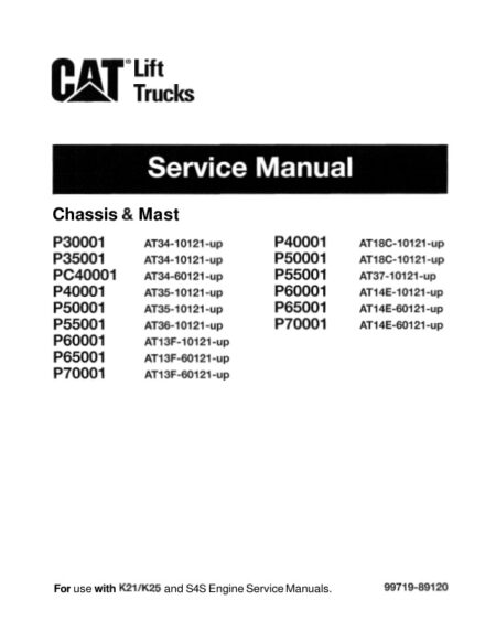 Service manual Caterpillar Cat Lift Trucks Chassis & Mast
4,99 $
ADD TO CART
Service manual Caterpillar Cat Lift Trucks Chassis & Mast
4,99 $
ADD TO CART
Reviews
There are no reviews yet.