


416F, 420F, 422F, 428F, 430F, 432F, 434F and 444F Backhoe Loaders Transmission (Autoshift)
– 28.pdf
– Flexible Coupling Drive
– General Information
– Governor Control
– Governor Control
– Machine Preparation for Troubleshooting
– Operational Checks
– Power Train Troubleshooting
– Pressure Taps
– Pump Drive
– Solenoid Valve (Autoshift)
– Solenoid Valve (Autoshift)
– Solenoid Valve (Autoshift)
– Solenoid Valve (Autoshift)
– Steering Lines
– Steering Lines
– Torque Converter
– Torque Converter
– Torque Converter
– Transmission
– Transmission (Autoshift) – All Wheel Drive
– Transmission (Autoshift) – All Wheel Drive
– Transmission (Autoshift) – Lockup Clutch
– Transmission (Autoshift) – Lockup Clutch
– Transmission and Torque Converter – Test
– Transmission and Torque Converter – Test
– Transmission Control
– Transmission Control
– Visual Inspection
416F, 420F, 422F, 428F, 430F, 432F, 434F and 444F Backhoe Loaders Transmission (Standard Shift)
– Flexible Coupling Drive
– General Information
– Governor Control
– Governor Control
– Machine Preparation for Troubleshooting
– Machine Preparation for Troubleshooting
– Operational Checks
– Power Train Troubleshooting
– Pressure Taps
– Pump Drive
– Solenoid Valve (Standard Shift)
– Solenoid Valve (Standard Shift)
– Steering Lines
– Steering Lines
– Torque Converter
– Torque Converter
– Torque Converter
– Transmission (All-Wheel Drive)
– Transmission (Standard Shift) – All Wheel Drive
– Transmission (Standard Shift) – All Wheel Drive
– Transmission (Standard Shift) – Two Wheel Drive
– Transmission (Standard Shift) – Two Wheel Drive
– Transmission (Two-Wheel Drive)
– Transmission and Torque Converter – Test
– Transmission Control
– Transmission Control
– Transmission Hydraulic System
– Visual Inspection
416F, 420F, 422F, 428F, 430F, 432F, 434F, 444F and 450F Backhoe Loaders Monitoring System
– Connector Contact Description
– Data Link
– Diagnostic Operation
– Display Module
– Electrical Connector – Inspect
– General Information
– Input Components
– Menus
– Module – Configure
– Module – Flash Program
– Module – Replace
– Monitoring System
– Output Components
– Self Test
– System Schematic
– Warning Operation
– Wiring Harness (Open Circuit) – Test
– Wiring Harness (Short Circuit) – Test
420F, 428F, 430F, 432F, 434F, 444F and 450F Backhoe Loaders Machine Electronic Control System
– Axle and Differential
– Backup Alarm Always Off
– Backup Alarm Always On
– Brake System
– Calibration
– Charging System
– Connector Contact Description
– Connector Locations
– Data Link
– Diagnostic Capabilities
– Diagnostic Code List
– Electrical Connector – Inspect
– Electrical Input Components
– Electrical Output Components
– Electronic Control Module
– Electronic Control Module (ECM) – Configure
– Electronic Control Module (ECM) – Flash Program
– Electronic Control Module (ECM) – Replace
– Emerging Symptom Information
– Event Code List
– Features
– General Information
– General Information
– Hydraulic System
– MID 039 – CID 0041 – FMI 03
– MID 039 – CID 0041 – FMI 04
– MID 039 – CID 0168 – FMI 03
– MID 039 – CID 0168 – FMI 04
– MID 039 – CID 0191 – FMI 02
– MID 039 – CID 0247 – FMI 09
– MID 039 – CID 0268 – FMI 02
– MID 039 – CID 0367 – FMI 04
– MID 039 – CID 0368 – FMI 03
– MID 039 – CID 0368 – FMI 04
– MID 039 – CID 0490 – FMI 03
– MID 039 – CID 0490 – FMI 04
– MID 039 – CID 0517 – FMI 02
– MID 039 – CID 0586 – FMI 02
– MID 039 – CID 0590 – FMI 09
– MID 039 – CID 0597 – FMI 03
– MID 039 – CID 0597 – FMI 04
– MID 039 – CID 0597 – FMI 08
– MID 039 – CID 0600 – FMI 03
– MID 039 – CID 0600 – FMI 04
– MID 039 – CID 0626 – FMI 02
– MID 039 – CID 0629 – FMI 04
– MID 039 – CID 0637 – FMI 06
– MID 039 – CID 0679 – FMI 03
– MID 039 – CID 0679 – FMI 05
– MID 039 – CID 0679 – FMI 06
– MID 039 – CID 0702 – FMI 02
– MID 039 – CID 0769 – FMI 03
– MID 039 – CID 0769 – FMI 04
– MID 039 – CID 0769 – FMI 08
– MID 039 – CID 0882 – FMI 03
– MID 039 – CID 0882 – FMI 05
– MID 039 – CID 0882 – FMI 06
– MID 039 – CID 1401 – FMI 03
– MID 039 – CID 1401 – FMI 05
– MID 039 – CID 1401 – FMI 06
– MID 039 – CID 1402 – FMI 03
– MID 039 – CID 1402 – FMI 05
– MID 039 – CID 1402 – FMI 06
– MID 039 – CID 1403 – FMI 03
– MID 039 – CID 1403 – FMI 05
– MID 039 – CID 1403 – FMI 06
– MID 039 – CID 1404 – FMI 03
– MID 039 – CID 1404 – FMI 05
– MID 039 – CID 1404 – FMI 06
– MID 039 – CID 1405 – FMI 03
– MID 039 – CID 1405 – FMI 05
– MID 039 – CID 1405 – FMI 06
– MID 039 – CID 1406 – FMI 03
– MID 039 – CID 1406 – FMI 05
– MID 039 – CID 1406 – FMI 06
– MID 039 – CID 1529 – FMI 02
– MID 039 – CID 1529 – FMI 04
– MID 039 – CID 1960 – FMI 09
– MID 039 – CID 2236 – FMI 02
– MID 039 – CID 2236 – FMI 03
– MID 039 – CID 2236 – FMI 05
– MID 039 – CID 2236 – FMI 06
– MID 039 – CID 2237 – FMI 02
– MID 039 – CID 2237 – FMI 03
– MID 039 – CID 2237 – FMI 05
– MID 039 – CID 2237 – FMI 06
– MID 039 – CID 2242 – FMI 02
– MID 039 – CID 2242 – FMI 03
– MID 039 – CID 2242 – FMI 05
– MID 039 – CID 2242 – FMI 06
– MID 039 – CID 2243 – FMI 02
– MID 039 – CID 2243 – FMI 03
– MID 039 – CID 2243 – FMI 05
– MID 039 – CID 2243 – FMI 06
– MID 039 – CID 2244 – FMI 02
– MID 039 – CID 2244 – FMI 03
– MID 039 – CID 2244 – FMI 05
– MID 039 – CID 2244 – FMI 06
– MID 039 – CID 2245 – FMI 02
– MID 039 – CID 2245 – FMI 03
– MID 039 – CID 2245 – FMI 05
– MID 039 – CID 2245 – FMI 06
– MID 039 – CID 2529 – FMI 02
– MID 039 – CID 2529 – FMI 03
– MID 039 – CID 2529 – FMI 04
– MID 039 – CID 2529 – FMI 08
– MID 039 – CID 2529 – FMI 13
– MID 039 – CID 2530 – FMI 02
– MID 039 – CID 2530 – FMI 03
– MID 039 – CID 2530 – FMI 04
– MID 039 – CID 2530 – FMI 08
– MID 039 – CID 2530 – FMI 13
– MID 039 – CID 2531 – FMI 02
– MID 039 – CID 2531 – FMI 03
– MID 039 – CID 2531 – FMI 04
– MID 039 – CID 2531 – FMI 08
– MID 039 – CID 2531 – FMI 13
– MID 039 – CID 2735 – FMI 03
– MID 039 – CID 2735 – FMI 04
– MID 039 – CID 2736 – FMI 03
– MID 039 – CID 2736 – FMI 04
– MID 039 – CID 2977 – FMI 03
– MID 039 – CID 2977 – FMI 04
– MID 039 – CID 2977 – FMI 07
– MID 039 – CID 3084 – FMI 03
– MID 039 – CID 3084 – FMI 04
– MID 039 – CID 3709 – FMI 03
– MID 039 – CID 3709 – FMI 05
– MID 039 – CID 3709 – FMI 06
– MID 039 – CID 3742 – FMI 03
– MID 039 – CID 3742 – FMI 05
– MID 039 – CID 3742 – FMI 06
– MID 122 – CID 0168 – FMI 01
– MID 122 – CID 1250 – FMI 09
– MID 416 – CID 0168 – FMI 03
– MID 416 – CID 0168 – FMI 04
– MID 416 – CID 0271 – FMI 05
– MID 416 – CID 0271 – FMI 06
– Operational Checks (All Wheel Steer)
– Operational Checks (Axle, Differential)
– Operational Checks (Brake System)
– Operational Checks (Hydraulic System)
– Operational Checks (Steering System)
– Operational Checks (Transmission)
– Power Supply Circuit of Electronic Control Module
– Service Tools
– Steering System
– Switch Circuits
– Symptom Troubleshooting
– System Schematic
– Transmission – Standard Shift
– Using Caterpillar Electronic Technician to Determine
– Using the Operator Monitor to Determine Diagnostic Codes
– Wiring Harness (Open Circuit) – Test
– Wiring Harness (Short Circuit) – Test
422F, 428F, 432F, 434F and 444F Backhoe Loaders Hydraulic and Steering System
– Bank Valve (Backhoe) – Mechanically Operated
– Bank Valve (Backhoe) – Pilot Operated
– Bank Valve (Loader) – Pilot Operated
– Bank Valve (Loader) – Single Tilt – Direct Operating
– Bucket Positioner and Kickout – Adjust
– Control Manifold (Sideshift) – If Equipped
– Control Manifold (Sideshift) – Powered Sideshift (If Equipped)
– Control Valve (Auxiliary)
– Control Valve (Auxiliary) – Mechanically Operated
– Control Valve (Auxiliary)(Loader) – Mechanically Operated
– Control Valve (Auxiliary)(Loader) – Pilot Operated
– Control Valve (Boom) – Mechanically Operated
– Control Valve (Boom) – Mechanically Operated
– Control Valve (Bucket) – Mechanically Operated
– Control Valve (Bucket) – Pilot Operated
– Control Valve (Extendable Stick) – Mechanically Operated
– Control Valve (Extendable Stick) – Pilot Operated
– Control Valve (Lift) – Mechanically Operated
– Control Valve (Lift) – Pilot Operated
– Control Valve (Stabilizer) – Mechanically Operated
– Control Valve (Stabilizer) – Pilot Operated
– Control Valve (Stick) – Mechanically Operated
– Control Valve (Stick) – Pilot Operated
– Control Valve (Swing) – Mechanically Operated
– Control Valve (Swing) – Pilot Operated
– Control Valve (Tilt) – Mechanically Operated
– Control Valve (Tilt) – Pilot Operated
– Crossover Relief Valve (Swing Cushion) – If Equipped
– General Information (Hydraulic System)
– General Information (Steering)
– Hydraulic Oil Contamination – Test
– Hydraulic Pump – Test and Adjust
– Hydraulic Pump – Test and Adjust
– Hydraulic System Lockout
– Hydraulic Tank and Filter
– Load Control Valve (Boom or Stick) – If Equipped
– Load Control Valve (Lift) – If Equipped
– Metering Pump (Steering)
– Pilot Oil Accumulator – Test and Charge
– Pilot System Pressure – Test
– Piston Pump (Work Tool and Steering)
– Piston Pump (Work Tool and Steering)
– Priority Valve – Inlet Manifold of the Loader
– Pump Flow – Test
– Relief Valve (Line) – Test and Adjust
– Relief Valve (Loader) – Test and Adjust
– Relief Valve (Steering Priority) – Test and Adjust
– Relief Valve (Steering) – Test and Adjust
– Ride Control – Test
– Ride Control Accumulator – Test and Charge
– Ride Control System
– Sideshift Slide Lock Circuit – If Equipped
– Sideshift Slide Lock Circuit – If Equipped
– Sideshift System – If Equipped
– System Pressure – Release
– Worksheets – Troubleshoot
Air Conditioning and Heating R134a for All Caterpillar Machines
– Refrigerant Compressor
– System Capacities for Refrigerant (Off-Highway Trucks)
– General Information
– Identifying the Refrigerant
– Identifying the Air Conditioning System
– Identifying the Heating System
– Refrigerant Expansion Valve System
– Refrigerant Orifice Tube System
– Refrigerant Compressor
– Refrigerant Condenser
– Refrigerant Receiver-Dryer
– Refrigerant Compressor
– Refrigerant Expansion Valve
– In-line Refrigerant Dryer
– Refrigerant Orifice Tube Assembly
– Evaporator Coil
– Refrigerant Accumulator
– Refrigerant Compressor Protection System
– Temperature Control
– Pressure Switch (Refrigerant)
– Cab Pressurization and Filtration System
– Condensate Drainage System
– Refrigerant Compressor
– Service Intervals
– Glossary of Terms
– Required Tools
– Machine Preparation for Troubleshooting
– General Troubleshooting Information
– General Troubleshooting Information
– Visual Inspection (Troubleshooting)
– Air Conditioning System Troubleshooting
– Heating System Troubleshooting
– Automatic Temperature Control System (ECM Controlled)
– Refrigerant Compressor
– Troubleshooting Heating and Air Conditioning Control System
– Troubleshooting Heating and Air Conditioning Control System
– Automatic Temperature Control Panel Troubleshooting – 584
– Troubleshooting Condensate Drainage System
– Machine Preparation for Testing and Adjusting
– Air Conditioning Performance – Test
– Refrigerant Leakage – Test
– Manifold Gauge Set (Refrigerant) – Install
– Refrigerant Recovery
– Refrigerant System – Flush
– Refrigerant Compressor
– Refrigerant Oil – Test
– Refrigerant Compressor – Test
– Refrigerant System – Evacuate
– Refrigerant System – Charge
– Manifold Gauge Set (Refrigerant) – Remove
– Compressor Protection System – Test
– Electronic Heat Control – Test
– Heater Performance – Test
– Heating and Air Conditioning Service Publications
– General Information
– Refrigerant Compressor
– Machine Preparation for Disassembly and Assembly
– Air Conditioner Lines – Remove and Install
– Refrigerant Compressor – Remove and Install
– Refrigerant Accumulator – Remove and Install
– Refrigerant Expansion Valve – Remove and Install
– Refrigerant Receiver-Dryer – Remove and Install
– In-Line Refrigerant Dryer – Remove and Install
– Refrigerant Orifice Tube Assembly – Remove and Install
– Refrigerant Compressor
– System Capacities for Refrigerant (Motor Graders)
– System Capacities for Refrigerant (Off-Highway Trucks) –
– Refrigerant Compressor
Disassembly and Assembly 416F, 420F, 422F, 428F, 430F, 432F, 434F and 444F Backhoe Loaders Engine Supplement
– Air Cleaner – Remove and Install
– Alternator – Remove and Install
– Alternator – Remove and Install
– Battery – Remove and Install
– Diesel Particulate Filter – Remove and Install
– Electric Starting Motor – Remove and Install
– Electric Starting Motor – Remove and Install – 434F and 444F
– Engine – Install
– Engine – Install
– Engine – Remove
– Engine – Remove
– Fan – Remove and Install
– Fan Drive – Remove and Install
– Fuel Filter and Water Separator – Remove and Install
– Fuel Priming Pump and Primary Filter (Water Separator) –
– Hood – Remove and Install
– Hydraulic and Transmission Oil Cooler – Remove and Install
– Muffler – Remove and Install
– Radiator – Remove and Install
– Radiator, Fuel Cooler, After Cooler, and Hydraulic and XMSN
– Refrigerant Compressor – Remove and Install
– Refrigerant Condenser – Remove and Install
– Side Panel – Remove and Install
– System Pressure – Release
– Turbocharger – Remove and Install
– Turbocharger – Remove and Install
– Water Pump – Remove and Install
– Water Temperature Regulator – Remove and Install
Disassembly and Assembly 416F, 420F, 422F, 428F, 430F, 432F, 434F and 444F Backhoe Loaders Power Train
– Axle Housing (Differential and Bevel Gear) (Front) –
– Axle Housing (Differential and Bevel Gear) (Front) – Assemble
– Axle Housing (Differential and Bevel Gear) (Front) – Remove
– Axle Housing (Service Brakes, Differential and Bevel Gear) –
– Axle Housing (Service Brakes, Differential and Bevel Gear) –
– Axle Housing (Service Brakes, Differential and Bevel Gear) –
– Axle Housing (Service Brakes, Differential and Bevel Gear) –
– Axle Housing and Flange – Assemble
– Axle Housing and Flange – Disassemble
– Axle Housing and Flange – Install
– Axle Housing and Flange – Remove
– Axle Housing, Axle Shaft, and Wheel Flange – Assemble
– Axle Housing, Axle Shaft, and Wheel Flange – Disassemble
– Axle Housing, Axle Shaft, and Wheel Flange – Install
– Axle Housing, Axle Shaft, and Wheel Flange – Install
– Axle Housing, Axle Shaft, and Wheel Flange – Remove
– Axle Housing, Axle Shaft, and Wheel Flange – Remove
– Axle Shaft – Remove and Install
– Drive and Steering Axle (Front) – Install
– Drive and Steering Axle (Front) – Remove
– Drive Shaft (Front) – Remove and Install
– Drive Shaft (Rear) – Remove and Install
– Final Drive Planetary – Remove and Install
– Parking Brake – Remove and Install
– Rear Axle – Install
– Rear Axle – Install
– Rear Axle – Remove
– Rear Axle – Remove
– Solenoid Valve (Transmission) – Remove and Install
– Steering Cylinder (Front) – Remove and Install
– System Pressure – Release
– Tie Rod (Steering)(Front) – Remove and Install
– Tire and Rim (Front) – Remove and Install
– Tire and Rim (Rear) – Remove and Install
– Transmission (Direct Drive) – Assemble
– Transmission (Direct Drive) – Disassemble
– Transmission (Direct Drive) – Install
– Transmission (Direct Drive) – Remove
– Transmission (Power Shift) – Assemble
– Transmission (Power Shift) – Disassemble
– Transmission (Power Shift) – Install
– Transmission (Power Shift) – Install – 434F & 444F
– Transmission (Power Shift) – Remove
– Transmission (Power Shift) – Remove – 434F & 444F
Disassembly and Assembly 422F, 428F, 432F, 434F and 444F Backhoe Loaders Machine Systems
– Air Conditioner and Heater – Remove and Install
– Backhoe Bucket Cylinder – Remove and Install
– Backhoe Bucket Linkage – Remove and Install
– Bank Valve (Backhoe) – Install – Mechanical Operated
– Bank Valve (Backhoe) – Install – Pilot Operated
– Bank Valve (Backhoe) – Remove – Mechanical Operated
– Bank Valve (Backhoe) – Remove – Pilot Operated
– Bank Valve (Loader) – Install – Mechanical Operated
– Bank Valve (Loader) – Install – Pilot Operated
– Bank Valve (Loader) – Remove – Mechanical Operated
– Bank Valve (Loader) – Remove – Pilot Operated
– Boom – Remove and Install
– Boom Cylinder – Remove and Install
– Bucket – Remove and Install
– Bucket Positioner Control – Remove and Install – Parallel Lift
– Bucket Positioner Control – Remove and Install – Single Tilt
– Cab – Install
– Cab – Remove
– Counterweight – Remove and Install
– Extendable Stick – Remove and Install
– Extendable Stick – Remove and Install
– Extendable Stick Cylinder – Remove and Install
– Fuel Tank – Remove and Install
– Hoe Bucket – Remove and Install
– Hydraulic Tank – Remove and Install
– Lift Arms – Remove and Install – Single Tilt
– Lift Arms – Remove and Install – Single Tilt
– Lift Cylinder – Remove and Install – Parallel Lift
– Lift Cylinder – Remove and Install – Single Tilt
– Piston Pump (Main Hydraulic) – Remove and Install
– Piston Pump – Assemble – Main Hydraulic
– Piston Pump – Disassemble – Main Hydraulic
– Quick Coupler – Remove and Install – Parallel Lift
– Refrigerant Accumulator – Remove and Install
– Ride Control Accumulator – Remove and Install
– Seat – Remove and Install
– Service Brake Control – Remove and Install
– Sliding Frame and Bearing – Install
– Sliding Frame and Bearing – Remove
– Stabilizer – Remove and Install
– Stabilizer Control Lever – Remove and Install – Mechanical
– Stabilizer Control Lever – Remove and Install – Pilot
– Stabilizer Cylinder – Remove and Install
– Steering Metering Pump – Remove and Install
– Steering Wheel – Remove and Install
– Stick – Remove and Install
– Stick Cylinder – Remove and Install
– Swing Cylinder – Remove and Install
– Swing Frame – Install
– Swing Frame – Remove
– System Pressure – Release
– Tilt Cylinder – Remove and Install – Parallel Lift
– Tilt Cylinder – Remove and Install – Single Tilt
– Window Wiper and Wiper Motor (Front) – Remove and Install
– Window Wiper and Wiper Motor (Rear) – Remove and Install
Disassembly and Assembly C4.4 Engines for Caterpillar Built Machines
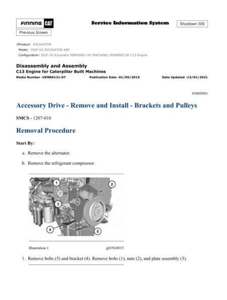
– Accessory Drive – Remove and Install – Accessory Drive SAE
– Accessory Drive – Remove and Install – Accessory Drive SAE
– Air Compressor – Remove and Install – Single Cylinder
– Air Compressor – Remove and Install – Twin Cylinder
– Alternator – Install
– Alternator – Remove
– Alternator Belt – Remove and Install
– Atmospheric Pressure Sensor – Remove and Install
– Balancer – Install
– Balancer – Remove
– Bearing Clearance – Check
– Belt Tensioner – Remove and Install
– Boost Pressure Sensor – Remove and Install
– Camshaft – Remove and Install
– Camshaft Bearings – Remove and Install
– Camshaft Gear – Remove and Install
– Camshaft Position Sensor – Remove and Install
– Connecting Rod Bearings – Install – Connecting Rods in
– Connecting Rod Bearings – Remove – Connecting Rods in
– Coolant Temperature Sensor – Remove and Install
– Crankcase Breather – Install
– Crankcase Breather – Remove
– Crankshaft – Install
– Crankshaft – Remove
– Crankshaft Front Seal – Remove and Install
– Crankshaft Front Seal – Remove and Install – Crankshaft Front
– Crankshaft Gear (Balancer Drive) – Remove and Install
– Crankshaft Gear – Remove and Install
– Crankshaft Main Bearings – Remove and Install – Crankshaft
– Crankshaft Position Sensor – Remove and Install
– Crankshaft Pulley – Remove and Install
– Crankshaft Rear Seal – Install
– Crankshaft Rear Seal – Remove
– Crankshaft Timing Ring – Remove and Install
– Cylinder Head – Install
– Cylinder Head – Remove
– Diesel Particulate Filter – Install
– Diesel Particulate Filter – Remove
– Electric Starting Motor – Remove and Install
– Electronic Control Module – Install
– Electronic Control Module – Remove
– Electronic Unit Injector – Install
– Electronic Unit Injector – Remove
– Engine Oil Cooler – Install
– Engine Oil Cooler – Remove
– Engine Oil Filter Base – Remove and Install
– Engine Oil Pan – Remove and Install – Aluminum and Pressed
– Engine Oil Pan – Remove and Install – Cast Iron Oil Pan
– Engine Oil Pressure Sensor – Remove and Install
– Engine Oil Pump – Install
– Engine Oil Pump – Remove
– Exhaust Back Pressure Valve – Remove and Install
– Exhaust Cooler (NRS) – Remove and Install – Side mounted
– Exhaust Cooler (NRS) – Remove and Install – Top mounted
– Exhaust Cooler (NRS) – Remove and Install – Twin
– Exhaust Elbow – Remove and Install
– Exhaust Elbow – Remove and Install – Top Mounted and Side
– Exhaust Manifold – Remove and Install – Single Turbocharger
– Exhaust Manifold – Remove and Install – Twin Turbocharger
– Fan – Remove and Install
– Fan Drive – Remove and Install
– Flexible Exhaust Pipe – Remove and Install
– Flow Control Valve – Remove and Install
– Flywheel – Install
– Flywheel – Remove
– Flywheel Housing – Remove and Install – Standard Housing
– Flywheel Housing – Remove and Install – Wet Back End
– Front Cover – Remove and Install
– Front Cover – Remove and Install – Heavy Duty Front Cover
– Fuel Filter Base – Remove and Install – Single Secondary Fuel
– Fuel Injection Lines – Install
– Fuel Injection Lines – Remove
– Fuel Injection Pump – Install
– Fuel Injection Pump – Remove
– Fuel Injection Pump Gear – Install
– Fuel Injection Pump Gear – Remove
– Fuel Manifold (Rail) – Remove and Install
– Fuel Pressure Sensor – Remove and Install
– Fuel Priming Pump – Remove and Install – Electric Fuel Lift
– Fuel Temperature Sensor – Remove and Install
– Gear Group (Front) – Remove and Install
– Gear Group (Front) – Remove and Install – Heavy Duty Gear
– Glow Plugs – Remove and Install
– Housing (Front) – Install
– Housing (Front) – Install – Heavy Duty Housing (Front)
– Housing (Front) – Remove
– Housing (Front) – Remove – Heavy Duty Housing (Front)
– Idler Gear – Install
– Idler Gear – Remove
– Idler Pulley – Remove and Install – Flat Idler Pulley
– Idler Pulley – Remove and Install – Grooved Idler Pulley
– Inlet Air Control – Install – NRS Induction Mixer
– Inlet Air Control – Remove – NRS Induction Mixer
– Inlet and Exhaust Valve Springs – Remove and Install
– Inlet and Exhaust Valves – Remove and Install
– Inlet Manifold Temperature Sensor – Remove and Install
– Lifter Group – Remove and Install – Hydraulic Lifter Group
– Piston Cooling Jets – Remove and Install
– Pistons and Connecting Rods – Assemble
– Pistons and Connecting Rods – Disassemble
– Pistons and Connecting Rods – Install
– Pistons and Connecting Rods – Remove
– Pressure Sensor (Cooled Exhaust Gas) – Remove and Install –
– Refrigerant Compressor – Remove and Install
– Relief Valve (Fuel) – Remove and Install
– Rocker Shaft – Assemble
– Rocker Shaft – Disassemble
– Rocker Shaft and Pushrod – Install
– Rocker Shaft and Pushrod – Remove
– Soot Antenna – Remove and Install
– Temperature Sensor (Cooled Exhaust Gas) – Remove and
– Temperature Sensor (DPF) – Remove and Install
– Turbocharger – Install – First Stage Turbocharger
– Turbocharger – Install – Second Stage Turbocharger
– Turbocharger – Install – Side Mounted Turbochargers
– Turbocharger – Install – Top Mounted Turbocharger
– Turbocharger – Remove – First Stage Turbocharger
– Turbocharger – Remove – Second Stage Turbocharger
– Turbocharger – Remove – Side Mounted Turbochargers
– Turbocharger – Remove – Top Mounted Turbocharger
– Valve Mechanism Cover – Remove and Install
– Wastegate Solenoid – Remove and Install
– Water Pump – Install
– Water Pump – Remove
– Water Separator and Fuel Filter (Primary) – Remove and
– Water Temperature Regulator – Remove and Install
Machine Security System (MSS3i) Integrated
– System Overview
– System Components
– Data Link
– General Information
– Troubleshooting
– Key – Program
– Scheduled Access – Program – Security System Bypass
– Time – Set
– Factory Password – Obtain
– Configuration
– Machine Security System – Uninstall
– Normal Operation
– Glossary of Terms
– System Schematic
– Operation of Status Indicator
– Key Information
– Scheduled Access – “Security System Bypass Times”
– Diagnostic Operation
– Protected Functions
– Service Operation Using Service Tool
– Electronic Control Module (ECM)
– General Information
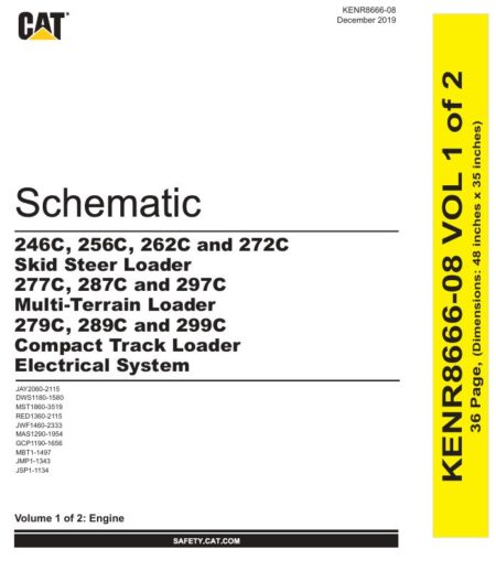
Schematic Caterpillar 432F and 444F Backhoe Loader Electrical System
– Features
– Cover page
– Tables
– Components
– Cab Wiring
– Chassis Wiring
– Engine Wiring
– Connector
– Cab Wiring
– Chassis Wiring
– Engine Wiring
– CID MID FMI
– Cab Wiring
– Chassis Wiring
– Related Manuals
– Schematic
– Cab Wiring
– Chassis Wiring
– Engine Wiring
– Machine Views
– Cab Wiring
– Rear Auxiliary Handle
– Left Console Wiring
– Left Console Wiring
– Dash Wiring
– Bucket Position Wiring
– Chassis Wiring
– Transmission Wiring – Standard
– Transmission Wiring – Automatic
– Rear End Wiring
– Quick Coupler Wiring – Left, Rear View
– Product Link Wiring
– Powered Sideshift Wiring
– Powered Sideshift Wiring
– Object Handling Wiring
– HVAC Wiring – Right Console
– Hoe Quick Coupler Wiring
– Headliner Wiring – Left, Rear View
– AWS Wiring – Left, Rear View
– Engine Wiring
– Right Side Engine Wiring
– Left Side Engine Wiring
Schematic Caterpillar 432F and 444F Backhoe Loader Hydraulic System
– Features
– Cover Page
– Information
– Component Location
– Page 1 of 2
– Page 2 of 2
– Tap Location
– Fluid Power Symbols
– Electrical Symbols
– Schematic
– Machine Views
– Machine View – Bottom
– Machine View – Left
– Machine View – Right Side
– Stick + E Stick
Specifications 416F, 420F, 422F, 428F, 430F, 432F, 434F and 444F Backhoe Loaders Axles, Differential and Brakes
– Axle (Front)
– Axle (Front) – Two-Wheel Drive
– Axle (Rear)
– Axle (Rear)
– Drive and Steering Axle (Front)
– Drive and Steering Axle (Rear)
– Drive Shaft
– Parking Brake Control
– Service Brake Control
– Service Brake Control
– Solenoid Valve and Mounting (Differential Lock)
– Switch (Differential Lock)
– Wheel and Tire (Front)
– Wheel and Tire (Rear) Wheel and Tire (Rear)
Specifications 422F, 428F, 432F, 434F and 444F Backhoe Loaders Hydraulic and Steering System
– Backhoe Control Mounting
– Bank Valve (Seven) (Mechanically Operated)
– Bank Valve (Seven) (Pilot Operated)
– Bank Valve (Three)(Mechanically Operated)
– Bank Valve (Three)(Mechanically Operated)
– Bank Valve (Three)(Pilot Operated)
– Bank Valve (Two)(Mechanically Operated)
– Boom Cylinder
– Boom Cylinder
– Bucket Cylinder (Backhoe)
– Bucket Linkage
– Bucket Linkage
– Bucket Linkage
– Bucket Linkage
– Bucket Positioner and Lift Kickout
– Control Manifold and Solenoid (Boom, Stick, Pattern Switch)
– Control Valve (Stabilizer) (Mechanically Operated)
– Control Valve (Stabilizer) (Pilot Operated)
– Crossover Relief Valve (Swing Cushion)
– Extendable Stick Cylinder
– Hydraulic Accumulator (Pilot Oil)
– Hydraulic Accumulator (Pilot Oil)
– Hydraulic Hand Control
– Hydraulic Hand Control (Loader) (Mechanically Operated)
– Hydraulic Pedal Control
– Hydraulic Tank and Mounting
– Joystick Control Mounting
– Lift Arm
– Lift Arm
– Lift Arm
– Lift Cylinder
– Lift Cylinder
– Lift Cylinder Brace
– Limit Switch (Service Brake)
– Metering Pump (Steering)
– Multipurpose Bucket Cylinder
– Oil Filter (Hydraulic)
– Pin Coupler Cylinder
– Piston Pump (Work Tool and Steering)
– Piston Pump (Work Tool and Steering)
– Radiator and Hydraulic Oil Cooler
– Ride Control Accumulator
– Ride Control Accumulator
– Ride Control Manifold
– Service Brake Control
– Service Brake Control
– Stabilizer Control
– Stabilizer Cylinder
– Steering Control
– Steering Cylinder (2WD)
– Steering Cylinder (2WD)
– Steering Valve and Mounting (AWS)
– Stick Cylinder
– Stick Cylinder
– Swing Cylinder
– Tilt Cylinder
– Tilt Cylinder
– Tilt Cylinder
– Transport Lock
– Transport Lock
Specifications C4.4 Engines for Caterpillar Built Machines
– Accessory Drive
– Alternator
– Atmospheric Pressure Sensor
– Belt Tensioner
– Boost Pressure Sensor
– Camshaft
– Camshaft Bearings
– Connecting Rod
– Connecting Rod Bearing Journal
– Coolant Temperature Sensor
– Crankcase Breather
– Crankshaft
– Crankshaft Pulley
– Crankshaft Seals
– Cylinder Block
– Cylinder Head
– Cylinder Head Valves
– Diesel Particulate Filter
– Electronic Control Module
– Engine Design
– Engine Lifting Bracket
– Engine Oil Cooler
– Engine Oil Filter Base
– Engine Oil Pan
– Engine Oil Pressure
– Engine Oil Pressure Sensor
– Engine Oil Pump
– Exhaust Cooler (NRS)
– Exhaust Gas Valve (NRS)
– Exhaust Manifold
– Exhaust Sensor and Lines (NRS)
– Fan Drive
– Flexible Exhaust Pipe
– Flywheel
– Flywheel Housing
– Front Housing and Covers
– Fuel Filter Base – Primary Fuel Filter Base
– Fuel Filter Base – Single Secondary Fuel Filter Base
– Fuel Injection Lines
– Fuel Injection Nozzles
– Fuel Injection Pump
– Fuel Manifold (Rail)
– Fuel Transfer Pump
– Gear Group (Front)
– Glow Plugs
– Inlet Manifold Temperature Sensor
– Lifter Group
– Main Bearing Journal
– Piston and Rings
– Piston Cooling Jet
– Pressure Sensor (NOx Reduction System)
– Refrigerant Compressor
– Rocker Shaft
– Speed/Timing Sensor
– Starter Motor
– Temperature Sensor (DPF Inlet)
– Temperature Sensor (NOx Reduction System)
– Turbocharger – Series Turbochargers
– Turbocharger – Single Turbocharger
– Valve Mechanism Cover
– Water Pump
– Water Temperature Regulator and Housing
Systems Operation & Testing and Adjusting 416F, 420F, 422F, 428F, 430F, 432F, 434F and 444F Backhoe Loaders Axles, Differential and Brakes
– Axle (Front)
– Axle (Front) – Adjust
– Axle (Rear)
– Axle Housing and Bearing Preload – Adjust
– Brake System Air – Purge
– Differential (Standard)
– Differential Backlash and Bearings – Adjust
– Differential Lock – If Equipped
– Differential Pinion Bearing – Adjust
– Drive and Steering Axle (Front)
– Drive and Steering Axle (Front) – Adjust
– Drive and Steering Axle (Rear)
– Drive and Steering Axle (Rear) – Adjust
– Parking Brake Control
– Service Brake Control
– Service Brake Control – Adjust
Systems Operation & Testing and Adjusting C4.4 Engines for Caterpillar Built Machines
– Air in Fuel – Test
– Air Inlet and Exhaust System – Inspect
– Air Inlet and Exhaust System – Series Turbochargers
– Air Inlet and Exhaust System – Series Turbochargers
– Air Inlet and Exhaust System – Single Turbocharger
– Air Inlet and Exhaust System – Single Turbocharger
– Alternator – Test
– Basic Engine
– Battery – Test
– Charging System – Test
– Clean Emissions Module
– Cleanliness of Fuel System Components
– Compression – Test
– Connecting Rod – Inspect
– Cooling System
– Cooling System – Check
– Cooling System – Inspect
– Cooling System – Test
– Crankshaft Pulley – Check
– Cylinder Block – Inspect
– Cylinder Head – Inspect
– Electric Starting System – Test
– Electrical System
– Electronic Control System
– Engine Oil Cooler – Inspect
– Engine Oil Pressure – Test
– Engine Oil Pump – Inspect
– Engine Valve Lash – Inspect
– Excessive Bearing Wear – Inspect
– Excessive Engine Oil Consumption – Inspect
– Exhaust Cooler (NRS) – Test
– Finding Top Center Position for No. 1 Piston
– Flywheel – Inspect
– Flywheel Housing – Inspect
– Fuel Injection
– Fuel Injection Timing – Check
– Fuel Quality – Test
– Fuel System – Inspect
– Fuel System – Prime
– Gear Group (Front) – Time
– Gear Group – Inspect
– Glossary of Electronic Control Terms
– Increased Engine Oil Temperature – Inspect
– Introduction
– Lubrication System
– Piston Height – Inspect
– Piston Ring Groove – Inspect
– Position the Valve Mechanism Before Maintenance Procedures
– Power Sources
– Turbocharger – Inspect – Series Turbochargers
– Turbocharger – Inspect – Single Turbocharger
– V-Belt – Test
– Valve Depth – Inspect
– Valve Guide – Inspect
– Water Pump – Inspect
– Water Temperature Regulator – Test
Systems Operation, Troubleshooting, Testing and Adjusting 420F, 428F, 430F, 432F, 434F and 444F Backhoe Loaders
– All Wheel Steer
– Axle and Differential
– Backup Alarm Always Off
– Backup Alarm Always On
– Brake System
– Calibration
– Charging System
– Connector Contact Description
– Connector Locations
– Data Link
– Diagnostic Capabilities
– Diagnostic Code List
– Electrical Connector – Inspect
– Electrical Input Components
– Electrical Output Components
– Electronic Control Module
– Electronic Control Module (ECM) – Configure
– Electronic Control Module (ECM) – Flash Program
– Electronic Control Module (ECM) – Replace
– Emerging Symptom Information
– Event Code List
– Features
– General Information
– General Information
– Hydraulic System
– MID 039 – CID 0041 – FMI 03
– MID 039 – CID 0041 – FMI 04
– MID 039 – CID 0168 – FMI 03
– MID 039 – CID 0168 – FMI 04
– MID 039 – CID 0191 – FMI 02
– MID 039 – CID 0268 – FMI 02
– MID 039 – CID 0367 – FMI 04
– MID 039 – CID 0368 – FMI 03
– MID 039 – CID 0368 – FMI 04
– MID 039 – CID 0490 – FMI 03
– MID 039 – CID 0490 – FMI 04
– MID 039 – CID 0517 – FMI 02
– MID 039 – CID 0597 – FMI 03
– MID 039 – CID 0597 – FMI 04
– MID 039 – CID 0597 – FMI 08
– MID 039 – CID 0600 – FMI 03
– MID 039 – CID 0600 – FMI 04
– MID 039 – CID 0626 – FMI 02
– MID 039 – CID 0629 – FMI 04
– MID 039 – CID 0637 – FMI 06
– MID 039 – CID 0679 – FMI 03
– MID 039 – CID 0679 – FMI 05
– MID 039 – CID 0679 – FMI 06
– MID 039 – CID 0702 – FMI 02
– MID 039 – CID 0769 – FMI 03
– MID 039 – CID 0769 – FMI 04
– MID 039 – CID 0769 – FMI 08
– MID 039 – CID 0882 – FMI 03
– MID 039 – CID 0882 – FMI 05
– MID 039 – CID 0882 – FMI 06
– MID 039 – CID 1251 – FMI 08
– MID 039 – CID 1401 – FMI 03
– MID 039 – CID 1401 – FMI 05
– MID 039 – CID 1401 – FMI 06
– MID 039 – CID 1402 – FMI 03
– MID 039 – CID 1402 – FMI 05
– MID 039 – CID 1402 – FMI 06
– MID 039 – CID 1403 – FMI 03
– MID 039 – CID 1403 – FMI 05
– MID 039 – CID 1403 – FMI 06
– MID 039 – CID 1404 – FMI 03
– MID 039 – CID 1404 – FMI 05
– MID 039 – CID 1404 – FMI 06
– MID 039 – CID 1405 – FMI 03
– MID 039 – CID 1405 – FMI 05
– MID 039 – CID 1405 – FMI 06
– MID 039 – CID 1406 – FMI 03
– MID 039 – CID 1406 – FMI 05
– MID 039 – CID 1406 – FMI 06
– MID 039 – CID 1529 – FMI 02
– MID 039 – CID 1529 – FMI 04
– MID 039 – CID 2236 – FMI 02
– MID 039 – CID 2236 – FMI 03
– MID 039 – CID 2236 – FMI 03
– MID 039 – CID 2236 – FMI 05
– MID 039 – CID 2236 – FMI 06
– MID 039 – CID 2236 – FMI 06
– MID 039 – CID 2237 – FMI 02
– MID 039 – CID 2237 – FMI 03
– MID 039 – CID 2237 – FMI 05
– MID 039 – CID 2237 – FMI 06
– MID 039 – CID 2242 – FMI 02
– MID 039 – CID 2242 – FMI 03
– MID 039 – CID 2242 – FMI 05
– MID 039 – CID 2242 – FMI 06
– MID 039 – CID 2243 – FMI 02
– MID 039 – CID 2243 – FMI 03
– MID 039 – CID 2243 – FMI 05
– MID 039 – CID 2243 – FMI 06
– MID 039 – CID 2244 – FMI 02
– MID 039 – CID 2244 – FMI 03
– MID 039 – CID 2244 – FMI 05
– MID 039 – CID 2244 – FMI 06
– MID 039 – CID 2245 – FMI 02
– MID 039 – CID 2245 – FMI 03
– MID 039 – CID 2245 – FMI 05
– MID 039 – CID 2245 – FMI 06
– MID 039 – CID 2529 – FMI 02
– MID 039 – CID 2529 – FMI 03
– MID 039 – CID 2529 – FMI 04
– MID 039 – CID 2529 – FMI 08
– MID 039 – CID 2529 – FMI 13
– MID 039 – CID 2530 – FMI 02
– MID 039 – CID 2530 – FMI 03
– MID 039 – CID 2530 – FMI 04
– MID 039 – CID 2530 – FMI 08
– MID 039 – CID 2530 – FMI 13
– MID 039 – CID 2531 – FMI 02
– MID 039 – CID 2531 – FMI 03
– MID 039 – CID 2531 – FMI 04
– MID 039 – CID 2531 – FMI 08
– MID 039 – CID 2531 – FMI 13
– MID 039 – CID 2735 – FMI 03
– MID 039 – CID 2735 – FMI 04
– MID 039 – CID 2736 – FMI 03
– MID 039 – CID 2736 – FMI 04
– MID 039 – CID 3709 – FMI 03
– MID 039 – CID 3709 – FMI 05
– MID 039 – CID 3709 – FMI 06
– MID 039 – CID 3742 – FMI 03
– MID 039 – CID 3742 – FMI 05
– MID 039 – CID 3742 – FMI 06
– Operational Checks (All Wheel Steer)
– Operational Checks (Axle, Differential)
– Operational Checks (Brake System)
– Operational Checks (Hydraulic System)
– Operational Checks (Steering System)
– Operational Checks (Transmission)
– Power Supply Circuit of Electronic Control Module
– Service Tools
– Steering System
– Switch Circuits
– Symptom Troubleshooting
– System Schematic
– Transmission – Standard Shift
– Using Caterpillar Electronic Technician to Determine
– Wiring Harness (Open Circuit) – Test
– Wiring Harness (Short Circuit) – Test
Troubleshooting C4.4 and C6.6 Engines
– Welding Precaution
– Diagnostic Trouble Codes
– Electrical Connectors – Inspect
– Cooling Fan – Calibrate – If Applicable
– Injector Code – Calibrate
– Event Codes
– Acceleration Is Poor or Throttle Response Is Poor
– Alternator Problem
– Battery Problem
– Belt Tensioner Noise
– Coolant Contains Oil
– Coolant Level Is Low
– Coolant Temperature Is High
– Coolant Temperature Is Low
– Electronic Service Tools
– Cooling Fan Is Always ON
– Crankcase Breather Ejects Oil
– Crankcase Fumes Disposal Tube Has Oil Draining
– Cylinder Is Noisy
– Diesel Particulate Filter Collects Excessive Soot
– Diesel Particulate Filter Temperature Is Low
– Engine Cranks but Does Not Start
– Engine Does Not Crank
– Engine Has Early Wear
– Engine Has Mechanical Noise (Knock)
– Service Information Report
– Engine Misfires, Runs Rough or Is Unstable
– Engine Overcrank Occurrence
– Engine Overspeeds
– Engine Shutdown Occurrence
– Engine Shutdown Occurs Intermittently
– Engine Stalls at Low RPM
– Engine Top Speed Is Not Obtained
– Engine Vibration Is Excessive
– Exhaust Has Excessive Black Smoke
– Exhaust Has Excessive White Smoke
– System Overview
– Exhaust System Contains Coolant
– Exhaust System Contains Oil
– Fuel Consumption Is Excessive
– Fuel Contains Water
– Fuel Rail Pressure Problem
– Fuel Temperature Is High
– Inlet Air Is Restricted
– Intake Manifold Air Pressure Is High
– Intake Manifold Air Pressure Is Low
– Intake Manifold Air Temperature Is High
– Component Location
– NRS Exhaust Gas Temperature Is High
– NRS Mass Flow Rate Problem
– Oil Consumption Is Excessive
– Oil Contains Coolant
– Oil Contains Fuel
– Oil Level Is Low
– Oil Pressure Is Low
– Power Is Intermittently Low or Power Cutout Is Intermittent
– Valve Lash Is Excessive
– Aftertreatment Identification Module – Test
– Engine Monitoring System
– CAN Data Link – Test
– Coolant Level – Test
– Cooling Fan Control – Test
– Cooling Fan Reversing – Test
– Cooling Fan Speed – Test
– Data Link – Test
– Data Link Configuration Status – Test
– Electrical Power Supply – Test
– Ether Starting Aid – Test
– Fuel Transfer Pump – Test
– Diagnostic Capabilities
– Glow Plug Starting Aid – Test
– Idle Validation – Test
– Indicator Lamp – Test
– Injector Data Incorrect – Test
– Injector Solenoid – Test
– Mode Selection – Test
– Motorized Valve – Test
– Power Take-Off – Test
– Relay – Test – Start Relay
– Sensor Calibration Required – Test
– Electrical Connectors
– Sensor Signal (Analog, Active) – Test
– Sensor Signal (Analog, Passive) – Test
– Sensor Supply – Test
– Shutdown (Ground Level) – Test
– Solenoid Valve – Test
– Soot Sensor – Test
– Speed Control (Analog) – Test
– Speed Control (PWM) – Test
– Speed/Timing – Test
– Switch Circuits – Test – Multiposition Throttle Switch
– Configuration Parameters
– Switch Circuits – Test – Air Filter Restriction Switch
– Valve Position – Test
– Water in Fuel – Test
– Customer Passwords
– Factory Passwords
– ECM Will Not Accept Factory Passwords
– Electronic Service Tool Does Not Communicate
– Test ECM Mode
– ECM Software – Install
– ECM – Replace
– General Information



Reviews
There are no reviews yet.