450E Backhoe Loader Axles, Differential and Brakes
– Axle (Rear)
– Axle Housing and Bearing Preload – Adjust
– Axle, Differential and Brake Troubleshooting
– Brake System Air – Purge
– Differential – Front
– Differential – Rear
– Differential Backlash and Bearings – Adjust
– Differential Lock – Rear Axle
– Differential Pinion Bearing – Adjust
– Drive and Steering Axle (Front)
– Drive and Steering Axle (Front) – Adjust
– General Information
– Parking Brake Control
– Parking Brake Control – Adjust
– Service Brake Control – Adjust
– Service Brake Control – Power Assist
– Service Brake Discs – Check
– Service Brakes – Test
– Visual Inspection
450E Backhoe Loader Hydraulic and Steering System
– Bank Valve (Backhoe) (Mechanically Operated)
– Bank Valve (Backhoe) (Pilot Operated)
– Bank Valve (Loader) (Mechanically Operated)
– Control Manifold
– Control Valve (Auxiliary) (Loader) (Mechanically Operated)
– Control Valve (Auxiliary) (Mechanically Operated)
– Control Valve (Auxiliary) (Pilot Operated)
– Control Valve (Boom) (Mechanically Operated)
– Control Valve (Boom) (Pilot Operated)
– Control Valve (Bucket) (Mechanically Operated)
– Control Valve (Bucket) (Pilot Operated)
– Control Valve (Extendable Stick) (Mechanically Operated)
– Control Valve (Extendable Stick) (Mechanically Operated)
– Control Valve (Extendable Stick) (Pilot Operated)
– Control Valve (Lift) (Mechanically Operated)
– Control Valve (Stabilizer) (Pilot Operated)
– Control Valve (Stick) (Mechanically Operated)
– Control Valve (Stick) (Pilot Operated)
– Control Valve (Swing) (Mechanically Operated)
– Control Valve (Swing) (Mechanically Operated)
– Control Valve (Swing) (Mechanically Operated)
– Control Valve (Swing) (Pilot Operated)
– Control Valve (Tilt) (Mechanically Operated)
– Crossover Relief Valve (Swing Cushion) – If Equipped
– Gear Pump (Implement) – Supplemental
– Gear Pump Flow – Test
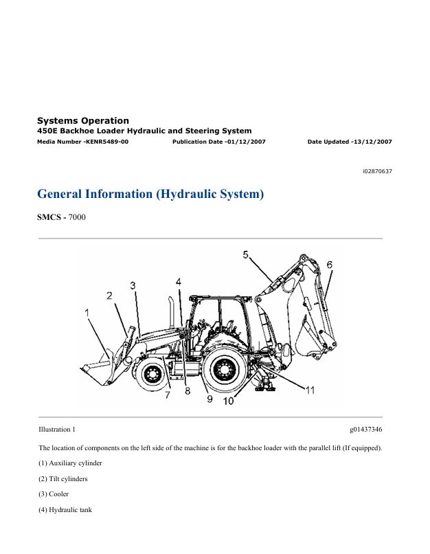
– General Information (Hydraulic System)
– General Information (Steering)
– Hydraulic Lockout Function
– Hydraulic Oil Contamination – Test
– Hydraulic Pump – Test and Adjust
– Hydraulic System Lockout
– Hydraulic System Troubleshooting
– Hydraulic Tank and Filter
– Load Check Valve
– Load Control Valve (Boom or Stick) – If Equipped
– Load Control Valve (Lift) – If Equipped
– Machine Preparation for Troubleshooting
– Makeup and Relief Valve
– Metering Pump (Steering)
– Operational Checks
– Pilot System Pressure – Test
– Piston Pump (Implement and Steering)
– Priority Valve – Inlet Manifold of the Loader
– Pump Flow – Test
– Relief Valve (Backhoe) – Test and Adjust
– Relief Valve (Line)
– Relief Valve (Line) – Test and Adjust
– Relief Valve (Loader) – Test and Adjust
– Relief Valve (Steering) – Test
– Ride Control – Test
– Ride Control Accumulator – Test and Charge
– Ride Control System
– Steering System Troubleshooting
– System Pressure – Release
– Visual Inspection
– Worksheets – Troubleshoot
450E Backhoe Loader Transmission (Autoshift)
– General Information
– Machine Preparation for Troubleshooting
– Operational Checks
– Power Train Troubleshooting
– Pressure Taps
– Solenoid Valve (Autoshift)
– Solenoid Valve (Autoshift)
– Solenoid Valve (Autoshift)
– Solenoid Valve (Autoshift)
– Torque Converter
– Torque Converter
– Transmission
– Transmission (Autoshift)
– Transmission and Torque Converter – Test
– Transmission Control
– Transmission Hydraulic System
– Visual Inspection
Air Conditioning and Heating R134a for All Caterpillar Machines
– Refrigerant Compressor
– System Capacities for Refrigerant (Off-Highway Trucks)
– General Information
– Identifying the Refrigerant
– Identifying the Air Conditioning System
– Identifying the Heating System
– Refrigerant Expansion Valve System
– Refrigerant Orifice Tube System
– Refrigerant Compressor
– Refrigerant Condenser
– Refrigerant Receiver-Dryer
– Refrigerant Compressor
– Refrigerant Expansion Valve
– In-line Refrigerant Dryer
– Refrigerant Orifice Tube Assembly
– Evaporator Coil
– Refrigerant Accumulator
– Refrigerant Compressor Protection System
– Temperature Control
– Pressure Switch (Refrigerant)
– Cab Pressurization and Filtration System
– Condensate Drainage System
– Refrigerant Compressor
– Service Intervals
– Glossary of Terms
– Required Tools
– Machine Preparation for Troubleshooting
– General Troubleshooting Information
– General Troubleshooting Information
– Visual Inspection (Troubleshooting)
– Air Conditioning System Troubleshooting
– Heating System Troubleshooting
– Automatic Temperature Control System (ECM Controlled)
– Refrigerant Compressor
– Troubleshooting Heating and Air Conditioning Control System
– Troubleshooting Heating and Air Conditioning Control System
– Automatic Temperature Control Panel Troubleshooting – 584
– Troubleshooting Condensate Drainage System
– Machine Preparation for Testing and Adjusting
– Air Conditioning Performance – Test
– Refrigerant Leakage – Test
– Manifold Gauge Set (Refrigerant) – Install
– Refrigerant Recovery
– Refrigerant System – Flush
– Refrigerant Compressor
– Refrigerant Oil – Test
– Refrigerant Compressor – Test
– Refrigerant System – Evacuate
– Refrigerant System – Charge
– Manifold Gauge Set (Refrigerant) – Remove
– Compressor Protection System – Test
– Electronic Heat Control – Test
– Heater Performance – Test
– Heating and Air Conditioning Service Publications
– General Information
– Refrigerant Compressor
– Machine Preparation for Disassembly and Assembly
– Air Conditioner Lines – Remove and Install
– Refrigerant Compressor – Remove and Install
– Refrigerant Accumulator – Remove and Install
– Refrigerant Expansion Valve – Remove and Install
– Refrigerant Receiver-Dryer – Remove and Install
– In-Line Refrigerant Dryer – Remove and Install
– Refrigerant Orifice Tube Assembly – Remove and Install
– Refrigerant Compressor
– System Capacities for Refrigerant (Motor Graders)
– System Capacities for Refrigerant (Off-Highway Trucks) –
– Refrigerant Compressor
Disassembly and Assembly 450E Backhoe Loader Engine Supplement
– Aftercooler – Remove and Install
– Air Cleaner – Remove and Install
– Alternator – Remove and Install
– Belt Tensioner – Remove and Install
– Cooling System Package (Radiator, Aftercooler, Hydraulic Oil
– Cooling System Package (Radiator, Aftercooler, Hydraulic Oil
– Crankshaft Pulley – Remove and Install
– Electric Starting Motor – Remove and Install
– Engine – Install
– Engine – Remove
– Engine Oil Filter and Base – Remove and Install
– Fan – Remove and Install
– Fan Drive – Remove and Install
– Fan Guard – Remove and Install
– Fuel Cooler – Remove and Install
– Fuel Filter and Base – Remove and Install
– Fuel Priming Pump and Primary Filter (Water Separator) –
– Hood – Remove and Install
– Hydraulic Oil Cooler – Remove and Install
– Muffler – Remove and Install
– Radiator – Remove and Install
– Refrigerant Compressor – Remove and Install
– Refrigerant Condenser – Remove and Install
– Side Panel – Remove and Install
– System Pressure – Release
– Transmission Oil Cooler – Remove and Install
– Turbocharger – Remove and Install
– Water Pump – Remove and Install
– Water Temperature Regulator – Remove and Install
Disassembly and Assembly 450E Backhoe Loader Machine Systems
– Air Conditioner and Heater – Install
– Air Conditioner and Heater – Remove
– Backhoe Bucket Cylinder – Remove and Install
– Backhoe Bucket Linkage – Remove and Install
– Bank Valve (Backhoe) – Assemble
– Bank Valve (Backhoe) – Disassemble
– Bank Valve (Backhoe) – Install
– Bank Valve (Backhoe) – Remove
– Bank Valve (Loader) – Assemble – Mechanical 2 Bank Valve
– Bank Valve (Loader) – Disassemble – Mechanical 2 Bank Valve
– Bank Valve (Loader) – Install
– Bank Valve (Loader) – Remove
– Boom – Remove and Install
– Boom Cylinder – Remove and Install
– Bucket Cylinder – Remove and Install
– Cab – Install
– Cab – Remove
– Counterweight – Remove and Install
– Disconnecting Snap To Connect Fittings
– Electronic Control Module (ECM) – Remove and Install
– Extendable Stick – Remove and Install
– Extendable Stick Cylinder – Remove and Install
– Gear Pump – Assemble
– Gear Pump – Disassemble
– Gear Pump – Install
– Gear Pump – Remove
– Hoe Bucket – Remove and Install
– Hydraulic Tank – Remove and Install
– Kickout and Positioner – Remove and Install
– Lift Arms – Install
– Lift Arms – Remove
– Lift Cylinder – Remove and Install
– Multipurpose Bucket – Remove and Install
– Pilot Valve (Backhoe) – Assemble
– Pilot Valve (Backhoe) – Disassemble
– Pilot Valve (Backhoe) – Install
– Pilot Valve (Backhoe) – Remove
– Pilot Valve (Stabilizer) – Install
– Pilot Valve (Stabilizer) – Remove
– Piston Pump – Assemble
– Piston Pump – Disassemble
– Piston Pump – Install
– Piston Pump – Remove
– Refrigerant Accumulator – Remove and Install
– Seat – Install
– Seat – Remove
– Service Brake Control – Install
– Service Brake Control – Remove
– Stabilizer – Remove and Install
– Stabilizer Cylinder – Remove and Install
– Steering Metering Pump – Install
– Steering Metering Pump – Remove
– Stick – Remove and Install
– Stick Cylinder – Remove and Install
– Swing Cylinder – Remove and Install
– Swing Frame – Install
– Swing Frame – Remove
– System Pressure – Release
– Tilt Cylinder – Remove and Install
– Window Wiper and Wiper Motor (Rear) – Install
– Window Wiper and Wiper Motor (Rear) – Remove
Disassembly and Assembly 450E Backhoe Loader Power Train
– Axle Housing (Differential and Bevel Gear) (Front) –
– Axle Housing (Differential and Bevel Gear) (Front) – Assemble
– Axle Housing (Differential and Bevel Gear) (Front) – Install
– Axle Housing (Differential and Bevel Gear) (Front) – Remove
– Axle Housing (Differential and Bevel Gear) (Rear) –
– Axle Housing (Differential and Bevel Gear) (Rear) – Assemble
– Axle Housing (Differential and Bevel Gear) (Rear) – Install
– Axle Housing (Differential and Bevel Gear) (Rear) – Remove
– Axle Housing and Flange – Assemble
– Axle Housing and Flange – Disassemble
– Axle Housing and Flange – Install
– Axle Housing and Flange – Remove
– Axle Shaft – Remove and Install
– Drive and Steering Axle (Front) – Install
– Drive and Steering Axle (Front) – Remove
– Drive Shaft (Front) – Remove and Install
– Drive Shaft (Rear) – Remove and Install
– Final Drive Planetary – Assemble – Front Axle
– Final Drive Planetary – Disassemble – Front Axle
– Final Drive Planetary – Install – Front Axle
– Final Drive Planetary – Remove – Front Axle
– Final Drive, Brake and Wheel – Assemble
– Final Drive, Brake and Wheel – Disassemble
– Final Drive, Brake and Wheel – Install
– Final Drive, Brake and Wheel – Remove
– Parking Brake – Remove and Install
– Rear Axle – Install
– Rear Axle – Remove
– Solenoid Valve (Transmission) – Install
– Solenoid Valve (Transmission) – Remove
– Steering Cylinder (Front) – Remove and Install
– Tie Rod (Steering)(Front) – Remove and Install
– Tire and Rim (Front) – Remove and Install
– Tire and Rim (Rear) – Remove and Install
– Transmission (Power Shift) – Assemble
– Transmission (Power Shift) – Disassemble
– Transmission (Power Shift) – Install
– Transmission (Power Shift) – Remove
– Transmission (Power Shift) – Remove
Disassembly and Assembly C4.4 Engines for Caterpillar Built Machines
– Accessory Drive – Assemble
– Accessory Drive – Disassemble
– Accessory Drive – Install
– Accessory Drive – Remove
– Air Compressor – Remove and Install
– Alternator – Install – Engines With an Automatic Belt Tensioner
– Alternator – Install – Engines Without an Automatic Belt
– Alternator – Remove – Engines With an Automatic Belt
– Alternator – Remove – Engines Without an Automatic Belt
– Alternator Belt – Remove and Install – Engines With an
– Balancer – Install
– Balancer – Remove
– Bearing Clearance – Check
– Boost Pressure Sensor – Remove and Install
– Camshaft – Remove and Install
– Camshaft Bearings – Remove and Install
– Camshaft Gear – Remove and Install
– Connecting Rod Bearings – Install – Connecting rods in position
– Connecting Rod Bearings – Remove – Connecting rods in
– Coolant Temperature Sensor – Remove and Install
– Crankcase Breather – Remove and Install – Filtered Breather
– Crankcase Breather – Remove and Install – Unfiltered Breather
– Crankshaft – Install
– Crankshaft – Remove
– Crankshaft Front Seal – Remove and Install
– Crankshaft Gear – Remove and Install
– Crankshaft Main Bearings – Remove and Install – Crankshaft
– Crankshaft Position Sensor – Remove and Install
– Crankshaft Pulley – Remove and Install – Engines With an
– Crankshaft Pulley – Remove and Install – Engines Without an
– Crankshaft Rear Seal – Install
– Crankshaft Rear Seal – Remove
– Crankshaft Timing Ring – Remove and Install
– Cylinder Head – Install
– Cylinder Head – Remove
– ECM Mounting Bracket – Remove and Install
– Electric Starting Motor – Remove and Install
– Electronic Control Module – Remove and Install
– Electronic Unit Injector – Install
– Electronic Unit Injector – Remove
– Engine Oil Cooler – Install
– Engine Oil Cooler – Remove
– Engine Oil Filter Base – Remove and Install
– Engine Oil Pan – Remove and Install – Aluminum and Pressed
– Engine Oil Pan – Remove and Install – Cast Iron Oil Pan
– Engine Oil Pressure Sensor – Remove and Install
– Engine Oil Pump – Remove and Install – Engines Without a
– Engine Oil Relief Valve – Remove and Install – Engines with a
– Engine Oil Relief Valve – Remove and Install – Engines Without
– Exhaust Elbow – Remove and Install
– Exhaust Manifold – Remove and Install
– Fan – Remove and Install
– Fan Drive – Remove and Install
– Flywheel – Install
– Flywheel – Remove
– Flywheel Housing – Remove and Install
– Front Cover – Remove and Install
– Fuel Filter Base – Remove and Install – Secondary Fuel Filter
– Fuel Injection Lines – Install
– Fuel Injection Lines – Remove
– Fuel Injection Pump – Install
– Fuel Injection Pump – Remove
– Fuel Injection Pump Gear – Install
– Fuel Injection Pump Gear – Remove
– Fuel Manifold (Rail) – Remove and Install
– Fuel Pressure Sensor – Remove and Install
– Fuel Priming Pump – Remove and Install – Electric Fuel
– Fuel Transfer Pump – Install
– Fuel Transfer Pump – Remove
– Gear Group (Front) – Remove and Install
– Glow Plugs – Remove and Install
– Housing (Front) – Install
– Housing (Front) – Remove
– Idler Gear – Install
– Idler Gear – Install
– Idler Gear – Install
– Idler Gear – Remove
– Idler Gear – Remove
– Idler Gear – Remove
– Inlet Air Temperature Sensor – Remove and Install
– Inlet and Exhaust Valve Springs – Remove and Install
– Inlet and Exhaust Valves – Remove and Install
– Lifter Group – Remove and Install
– Piston Cooling Jets – Remove and Install
– Pistons and Connecting Rods – Assemble
– Pistons and Connecting Rods – Disassemble
– Pistons and Connecting Rods – Install
– Pistons and Connecting Rods – Remove
– Position Sensor (Fuel Injection Pump) – Remove and Install
– Rocker Shaft – Assemble
– Rocker Shaft – Disassemble
– Rocker Shaft and Pushrod – Install
– Rocker Shaft and Pushrod – Remove
– Turbocharger – Install
– Turbocharger – Remove
– V-Belts – Remove and Install – Engines Without an Automatic
– Vacuum Pump – Remove and Install
– Valve Mechanism Cover – Remove and Install
– Valve Mechanism Cover Base – Remove and Install
– Wastegate Solenoid – Remove and Install
– Water Pump – Install
– Water Pump – Remove
– Water Temperature Regulator – Remove and Install
Schematic Caterpillar 450E Backhoe Loader Electrical System
Schematic Caterpillar 450E Backhoe Loader Hydraulic System
Specifications 450E Backhoe Loader Axles, Differential and Brakes
– Axle (Rear)
– Differential Lock Control
– Drive and Steering Axle (Front)
– Drive Shaft
– Parking Brake Control
– Service Brake Control
– Solenoid Valve (Differential Lock)
– Switch (Differential Lock)
– Wheel and Tire (Front)
– Wheel and Tire (Rear) Wheel and Tire (Rear)
Specifications 450E Backhoe Loader Hydraulic and Steering System
– Bank Valve (Eight) (Mechanically Operated)
– Bank Valve (Eight) (Pilot Operated)
– Bank Valve (Seven) (Mechanically Operated)
– Bank Valve (Seven) (Pilot Operated)
– Bank Valve (Three)(Mechanically Operated)
– Bank Valve (Two)(Mechanically Operated)
– Boom Cylinder
– Bucket Cylinder (Backhoe)
– Bucket Positioner and Lift Kickout
– Control Manifold (Mechanically Operated)
– Control Valve (Auxiliary) (Mechanically Operated)
– Control Valve (Auxiliary) (Pilot Operated)
– Control Valve (Auxiliary)(Loader) (Mechanically Operated)
– Control Valve (Backhoe Bucket) (Pilot Operated)
– Control Valve (Backhoe Bucket)(Mechanically Operated)
– Control Valve (Boom)(Mechanically Operated)
– Control Valve (Boom)(Pilot Operated)
– Control Valve (Extendable Stick) (Mechanically Operated)
– Control Valve (Extendable Stick) (Pilot Operated)
– Control Valve (Lift)(Mechanically Operated)
– Control Valve (Stabilizer)
– Control Valve (Stick)(Mechanically Operated)
– Control Valve (Stick)(Pilot Operated)
– Control Valve (Swing)(Mechanically Operated)
– Control Valve (Swing)(Pilot Operated)
– Control Valve (Tilt)(Mechanically Operated)
– Crossover Relief Valve (Swing Cushion)
– Extendable Stick Cylinder
– Gear Pump (Implement)
– Hydraulic Hand Control (Backhoe)
– Hydraulic Hand Control (Backhoe)
– Hydraulic Hand Control (Loader) (Mechanically Operated)
– Hydraulic Pedal Control (LH)
– Hydraulic Pedal Control (RH)
– Hydraulic Tank and Mounting
– Joystick Control (Backhoe)
– Lift Arm
– Lift Cylinder
– Loader Bucket Linkage
– Metering Pump (Steering)
– Multipurpose Bucket Cylinder
– Oil Filter (Hydraulic)
– Piston Pump (Implement and Steering)
– Priority Valve
– Pump Control Valve
– Pump Control Valve
– Relief Valve
– Ride Control Accumulator
– Solenoid Valve and Mounting (Ride Control)
– Stabilizer Cylinder
– Stick Cylinder
– Swing Cylinder
– Tilt Cylinder
– Transport Lock
Specifications C4.4 Engines for Caterpillar Built Machines
– Alternator
– Belt Tension Chart
– Boost Pressure Sensor
– Camshaft
– Camshaft Bearings
– Connecting Rod – For Use With Spheroidal Graphite Iron
– Connecting Rod – For Use With Steel Crankshaft
– Connecting Rod Bearing Journal – Spheroidal Graphite Iron
– Connecting Rod Bearing Journal – Steel Crankshaft
– Coolant Temperature Sensor
– Crankcase Breather
– Crankshaft – Spheroidal Graphite Iron (SGI) Crankshaft
– Crankshaft – Steel Crankshaft
– Crankshaft Position Sensor
– Crankshaft Pulley
– Crankshaft Seals
– Cylinder Block
– Cylinder Head
– Cylinder Head Valves
– Electronic Control Module
– Engine Design
– Engine Lifting Bracket
– Engine Oil Bypass Valve
– Engine Oil Cooler
– Engine Oil Filter Base
– Engine Oil Pan
– Engine Oil Pressure
– Engine Oil Pressure Sensor
– Engine Oil Pump
– Exhaust Manifold
– Flywheel
– Flywheel Housing
– Front Housing and Covers
– Fuel Filter
– Fuel Filter Base
– Fuel Injection Lines
– Fuel Injection Nozzles
– Fuel Injection Pump
– Fuel Pressure Sensor
– Fuel Priming Pump
– Fuel Transfer Pump
– Gear Group (Front)
– Glow Plugs
– Inlet Manifold Temperature Sensor
– Lifter Group
– Main Bearing Journal – Spheroidal Graphite Iron (SGI)
– Main Bearing Journal – Steel Crankshaft
– Piston and Rings
– Piston Cooling Jet
– Rocker Shaft
– Starter Motor
– Turbocharger
– Valve Mechanism Cover
– Water Pump
– Water Temperature Regulator and Housing
– Water Temperature Regulator and Housing
Systems Operation & Testing and Adjusting C4.4 Engines for Caterpillar Built Machines
– Air in Fuel – Test
– Air Inlet and Exhaust System
– Air Inlet and Exhaust System – Inspect
– Alternator – Test
– Basic Engine
– Battery – Test
– Charging System – Test
– Cleanliness of Fuel System Components
– Compression – Test
– Connecting Rod – Inspect
– Cooling System
– Cooling System – Check
– Cooling System – Inspect
– Cooling System – Test
– Crankshaft Pulley – Check
– Cylinder Block – Inspect
– Cylinder Head – Inspect
– Electric Starting System – Test
– Electrical System
– Electronic Control System
– Engine Oil Cooler – Inspect
– Engine Oil Pressure – Test
– Engine Oil Pump – Inspect
– Engine Valve Lash – Inspect/Adjust
– Excessive Bearing Wear – Inspect
– Excessive Engine Oil Consumption – Inspect
– Finding Top Center Position for No. 1 Piston
– Flywheel – Inspect
– Flywheel Housing – Inspect
– Fuel Injection
– Fuel Injection Timing – Check
– Fuel Quality – Test
– Fuel System – Inspect
– Fuel System – Prime
– Gear Group (Front) – Time
– Gear Group – Inspect
– Glossary of Electronic Control Terms
– Glow Plugs – Test
– Increased Engine Oil Temperature – Inspect
– Introduction
– Lubrication System
– Piston Height – Inspect
– Piston Ring Groove – Inspect
– Power Sources
– Turbocharger – Inspect
– V-Belt – Test
– Valve Depth – Inspect
– Valve Guide – Inspect
– Water Pump – Inspect
– Water Temperature Regulator – Test
Systems Operation & Troubleshooting 450E Backhoe Loader
– Axle and Differential
– Backup Alarm Always Off
– Backup Alarm Always On
– Brake System
– Calibration
– Charging System
– Connector Contact Description
– Connector Locations
– Data Link
– Diagnostic Capabilities
– Diagnostic Code List
– Electrical Connector – Inspect
– Electrical Input Components
– Electrical Output Components
– Electronic Control Module
– Electronic Control Module (ECM) – Configure
– Electronic Control Module (ECM) – Configure
– Electronic Control Module (ECM) – Flash Program
– Electronic Control Module (ECM) – Replace
– Event Code List
– Features
– General Information
– General Information
– Hydraulic System
– Location of Electrical Components
– Machine Preparation for Troubleshooting
– MID 039 – CID 0041 – FMI 03
– MID 039 – CID 0041 – FMI 04
– MID 039 – CID 0168 – FMI 03
– MID 039 – CID 0168 – FMI 04
– MID 039 – CID 0191 – FMI 02
– MID 039 – CID 0247 – FMI 09
– MID 039 – CID 0367 – FMI 04
– MID 039 – CID 0368 – FMI 03
– MID 039 – CID 0368 – FMI 04
– MID 039 – CID 0490 – FMI 03
– MID 039 – CID 0490 – FMI 04
– MID 039 – CID 0590 – FMI 02
– MID 039 – CID 0590 – FMI 09
– MID 039 – CID 0590 – FMI 12
– MID 039 – CID 0600 – FMI 03
– MID 039 – CID 0600 – FMI 04
– MID 039 – CID 0626 – FMI 02
– MID 039 – CID 0629 – FMI 04
– MID 039 – CID 0668 – FMI 02
– MID 039 – CID 0668 – FMI 09
– MID 039 – CID 0668 – FMI 12
– MID 039 – CID 1401 – FMI 03
– MID 039 – CID 1401 – FMI 05
– MID 039 – CID 1401 – FMI 06
– MID 039 – CID 1402 – FMI 03
– MID 039 – CID 1402 – FMI 05
– MID 039 – CID 1402 – FMI 06
– MID 039 – CID 1403 – FMI 03
– MID 039 – CID 1403 – FMI 05
– MID 039 – CID 1403 – FMI 06
– MID 039 – CID 1404 – FMI 03
– MID 039 – CID 1404 – FMI 05
– MID 039 – CID 1404 – FMI 06
– MID 039 – CID 1405 – FMI 03
– MID 039 – CID 1405 – FMI 05
– MID 039 – CID 1405 – FMI 06
– MID 039 – CID 1406 – FMI 03
– MID 039 – CID 1406 – FMI 05
– MID 039 – CID 1406 – FMI 06
– MID 039 – CID 1834 – FMI 04
– MID 039 – CID 2236 – FMI 02
– MID 039 – CID 2236 – FMI 03
– MID 039 – CID 2236 – FMI 05
– MID 039 – CID 2236 – FMI 06
– MID 039 – CID 2237 – FMI 02
– MID 039 – CID 2237 – FMI 03
– MID 039 – CID 2237 – FMI 05
– MID 039 – CID 2237 – FMI 06
– MID 039 – CID 2242 – FMI 02
– MID 039 – CID 2242 – FMI 03
– MID 039 – CID 2242 – FMI 05
– MID 039 – CID 2242 – FMI 06
– MID 039 – CID 2243 – FMI 02
– MID 039 – CID 2243 – FMI 03
– MID 039 – CID 2243 – FMI 05
– MID 039 – CID 2243 – FMI 06
– MID 039 – CID 2244 – FMI 02
– MID 039 – CID 2244 – FMI 03
– MID 039 – CID 2244 – FMI 05
– MID 039 – CID 2244 – FMI 06
– MID 039 – CID 2245 – FMI 02
– MID 039 – CID 2245 – FMI 03
– MID 039 – CID 2245 – FMI 05
– MID 039 – CID 2245 – FMI 06
– MID 039 – CID 2529 – FMI 02
– MID 039 – CID 2529 – FMI 03
– MID 039 – CID 2529 – FMI 04
– MID 039 – CID 2529 – FMI 08
– MID 039 – CID 2529 – FMI 13
– MID 039 – CID 2530 – FMI 02
– MID 039 – CID 2530 – FMI 03
– MID 039 – CID 2530 – FMI 04
– MID 039 – CID 2530 – FMI 08
– MID 039 – CID 2530 – FMI 13
– MID 039 – CID 2531 – FMI 02
– MID 039 – CID 2531 – FMI 03
– MID 039 – CID 2531 – FMI 04
– MID 039 – CID 2531 – FMI 08
– MID 039 – CID 2531 – FMI 13
– MID 039 – CID 2736 – FMI 03
– MID 039 – CID 2736 – FMI 04
– Operational Checks (Axle, Differential)
– Operational Checks (Brake System)
– Operational Checks (Hydraulic System)
– Operational Checks (Steering System)
– Operational Checks (Transmission)
– Power Supply Circuit of Electronic Control Module
– Service Tools
– Steering System
– Switch Circuits
– System Schematic
– Transmission – Autoshift
– Using Caterpillar Electronic Technician to Determine
– Visual Inspection
– Wiring Harness (Open Circuit) – Test
– Wiring Harness (Short Circuit) – Test
Troubleshooting C4.4 Engines For Caterpillar Built Machines
– 5 Volt Sensor Supply Circuit – Test
– Alternator Noise
– Alternator Will Not Charge
– Battery
– CAN Data Link Circuit – Test
– Can Not Reach Top Engine RPM
– CID 0001 FMI 02
– CID 0001 FMI 05
– CID 0001 FMI 06
– CID 0001 FMI 07
– CID 0002 FMI 02
– CID 0002 FMI 05
– CID 0002 FMI 06
– CID 0002 FMI 07
– CID 0003 FMI 02
– CID 0003 FMI 05
– CID 0003 FMI 06
– CID 0003 FMI 07
– CID 0004 FMI 02
– CID 0004 FMI 05
– CID 0004 FMI 06
– CID 0004 FMI 07
– CID 0041 FMI 03
– CID 0041 FMI 04
– CID 0091 FMI 03
– CID 0091 FMI 04
– CID 0091 FMI 08
– CID 0100 FMI 03
– CID 0100 FMI 04
– CID 0100 FMI 10
– CID 0110 FMI 03
– CID 0110 FMI 04
– CID 0168 FMI 00
– CID 0168 FMI 01
– CID 0168 FMI 02
– CID 0172 FMI 03
– CID 0172 FMI 04
– CID 0190 FMI 08
– CID 0247 FMI 09
– CID 0253 FMI 02
– CID 0261 FMI 11
– CID 0262 FMI 03
– CID 0262 FMI 04
– CID 0268 FMI 02
– CID 0342 FMI 08
– CID 0444 FMI 05
– CID 0444 FMI 06
– CID 0526 FMI 05
– CID 0526 FMI 06
– CID 0526 FMI 07
– CID 1639 FMI 02
– CID 1639 FMI 09
– CID 1779 FMI 05
– CID 1779 FMI 06
– CID 1785 FMI 03
– CID 1785 FMI 04
– CID 1785 FMI 10
– CID 1797 FMI 03
– CID 1797 FMI 04
– CID 1834 FMI 02
– CID 2246 FMI 06
– Coolant in Engine Oil
– Coolant Temperature Is Too High
– Customer Specified Parameters
– Customer Specified Parameters Table
– Customer Specified Parameters Worksheet
– Data Link Circuit – Test
– Diagnostic Code Cross Reference
– Digital Throttle Position Sensor Circuit – Test
– E1044 High Intake Manifold Pressure
– E1045 Low Intake Manifold Pressure
– E172 High Air Filter Restriction
– E194 High Exhaust Temperature
– E360 Low Engine Oil Pressure
– E361 High Engine Coolant Temperature
– E362 Engine Overspeed
– E396 High Fuel Rail Pressure
– E398 Low Fuel Rail Pressure
– E539 High Intake Manifold Air Temperature
– ECM Harness Connector Terminals
– ECM Memory – Test
– ECM Will Not Accept Factory Passwords
– ECM Will Not Communicate with Other Systems or Display
– Electrical Connectors – Inspect
– Electronic Service Tool Will Not Communicate with ECM
– Electronic Service Tools
– Engine Cranks but Will Not Start
– Engine Has Early Wear
– Engine Misfires, Runs Rough or Is Unstable
– Engine Oil in Cooling System
– Engine Pressure Sensor Open or Short Circuit – Test
– Engine Speed Does Not Change
– Engine Speed/Timing Sensor Circuit – Test
– Engine Stalls at Low RPM
– Engine Temperature Sensor Open or Short Circuit – Test
– Engine Vibration
– Engine Will Not Crank
– Engine Wiring Information
– Event Codes
– Excessive Black Smoke
– Excessive Engine Oil Consumption
– Excessive Fuel Consumption
– Excessive Valve Lash
– Excessive White Smoke
– Factory Passwords
– Flash Programming
– Fuel Rail Pump Solenoid – Test
– Glossary
– Ignition Keyswitch Circuit and Battery Supply Circuit – Test
– Injector Data Incorrect – Test
– Injector Solenoid Circuit – Test
– Injector Trim File
– Intake Air Temperature Is Too High
– Intermittent Engine Shutdown
– Intermittent Low Power or Power Cutout
– Low Engine Oil Pressure
– Low Power/Poor or No Response to Throttle
– Mechanical Noise (Knock) in Engine
– Noise Coming from Cylinder
– Programming Parameters
– Replacing the ECM
– Self-Diagnostics
– Sensors and Electrical Connectors
– Start Relay Circuit – Test
– Starting Aid (Glow Plug) Relay Circuit – Test
– System Configuration Parameters
– System Overview
– Test ECM Mode
– Throttle Setup
– Wastegate Solenoid – Test
Service manual Caterpillar 450E Backhoe Loader Center Pivot with C4.4 Engine | EBL00001-UP
29,99 $
Format: PDF
Type: Service Manual
Pages: 4192
Size: 191 Mb
No.: EBL00001-UP
-
 Schematic Caterpillar 416C, 426C, 436C Backhoe Loader Electrical System | RENR2855-01
4,99 $
ADD TO CART
Schematic Caterpillar 416C, 426C, 436C Backhoe Loader Electrical System | RENR2855-01
4,99 $
ADD TO CART -
 Schematic Caterpillar 336F & 340F Excavator 336F MHPU | UENR3622-06
4,99 $
ADD TO CART
Schematic Caterpillar 336F & 340F Excavator 336F MHPU | UENR3622-06
4,99 $
ADD TO CART -
 Schematic Caterpillar 924K, 930K & 938K Wheel Loader Electrical System | M0115907-00
9,99 $
ADD TO CART
Schematic Caterpillar 924K, 930K & 938K Wheel Loader Electrical System | M0115907-00
9,99 $
ADD TO CART -
 Service manual Caterpillar 336F & 336F L Excavators with C9.3 Engine | YFD00001-UP
29,99 $
ADD TO CART
Service manual Caterpillar 336F & 336F L Excavators with C9.3 Engine | YFD00001-UP
29,99 $
ADD TO CART -
 Service manual Caterpillar 323F LN Excavator with C4.4 Engine | FA210101-UP
29,99 $
ADD TO CART
Service manual Caterpillar 323F LN Excavator with C4.4 Engine | FA210101-UP
29,99 $
ADD TO CART -
 Schematic Caterpillar 966M, 966M XE, 972M and 972M XE Wheel Loader Electrical System | UENR7134-03
4,99 $
ADD TO CART
Schematic Caterpillar 966M, 966M XE, 972M and 972M XE Wheel Loader Electrical System | UENR7134-03
4,99 $
ADD TO CART
Reviews
There are no reviews yet.