3056E Engines for Caterpillar Built Machines
– Air in Fuel – Test
– Air Inlet and Exhaust System
– Air Inlet and Exhaust System – Inspect
– Air Inlet Heater – Test
– Alternator – Test
– Basic Engine
– Battery – Test
– Belt Tension Chart
– Charging System – Test
– Compression – Test
– Connecting Rod – Inspect
– Cooling System
– Cooling System – Check
– Cooling System – Inspect
– Cooling System – Test
– Cylinder Block – Inspect
– Cylinder Head – Inspect
– Cylinder Liner Projection – Inspect
– Electric Starting System – Test
– Electrical System
– Electronic Control System
– Engine Oil Cooler – Inspect
– Engine Oil Pressure – Test
– Engine Oil Pump – Inspect
– Engine Speed – Check
– Engine Valve Lash – Inspect/Adjust
– Excessive Bearing Wear – Inspect
– Excessive Engine Oil Consumption – Inspect
– Finding Top Center Position for No. 1 Piston
– Flywheel – Inspect
– Flywheel Housing – Inspect
– Fuel Injection
– Fuel Injection Nozzle – Test
– Fuel Injection Timing – Check
– Fuel Quality – Test
– Fuel System – Inspect
– Fuel System – Prime
– Fuel System Pressure – Test
– Gear Group (Front) – Time
– Gear Group – Inspect
– Increased Engine Oil Temperature – Inspect
– Introduction
– Lubrication System
– Piston Height – Inspect
– Piston Ring Groove – Inspect
– Power Sources
– Turbocharger – Inspect
– Valve Depth – Inspect
– Valve Guide – Inspect
– Vibration Damper – Check
– Water Pump – Inspect
– Water Temperature Regulator – Test
930G Wheel Loader Braking and Hydraulic Fan System
– Brake Accumulator
– Brake Accumulator
– Brake Accumulator – Test and Charge
– Brake and Planetary
– Brake Control Valve (Service)
– Brake Control Valve (Service)
– Brake System Air – Purge
– Gear Motor (Hydraulic Fan)
– Gear Motor (Hydraulic Fan)
– Gear Motor (Hydraulic Fan) – Reversing
– Gear Pump (Brake, Hydraulic Fan)
– Gear Pump (Brake, Hydraulic Fan)
– Gear Pump (Brake, Hydraulic Fan)
– Gear Pump (Brake, Hydraulic Fan)
– General Information (Braking)
– General Information (Braking)
– Hydraulic Fan Speed – Calibrate
– Hydraulic Oil Contamination – Test
– Hydraulic Oil Cooler
– Hydraulic Tank
– Limit Switch (Parking Brake)
– Oil Filter (Hydraulic)
– Parking Brake
– Parking Brake
– Parking Brake – Manual Release
– Parking Brake – Test
– Parking Brake Control – Adjust
– Pressure Sensor (Brake Oil)
– Pressure Sensor (Brake System Oil)
– Service Brake Control (Pedals) – Adjust
– Service Brake Discs – Check
– Service Brake System Pressure – Test
– Service Brakes
– Service Brakes – Test
– Solenoid Valve (Brake Charging) (Hydraulic Fan Oil Diverter)
– Solenoid Valve (Demand Fan)
– Solenoid Valve (Reversing Fan)
– System Pressure – Release
– Transmission Neutralization Setpoint – Adjust
– Worksheets
930G Wheel Loader Hydraulic System
– Auxiliary Control (Fifth and Sixth Functions)
– Control Valve (Auxiliary)
– Control Valve (Lift)
– Control Valve (Tilt)
– Coupler Control
– General Information
– General Testing and Adjusting Information
– Hydraulic Oil Contamination – Test
– Hydraulic Oil Cooler
– Load Control Valve (Lock)
– Main Control Valve
– Oil Filter (Hydraulic)
– Oil Filter (Hydraulic)
– Pilot Hydraulic System
– Pilot Oil Accumulator – Test and Charge
– Pilot System Pressure – Test
– Pilot Valve
– Piston Pump (Steering, Implement, Pilot)
– Piston Pump (Steering, Implement, Pilot) High Pressure Stall –
– Piston Pump (Steering, Implement, Pilot) Low Pressure
– Piston Pump (Steering, Implement, Pilot) Margin Pressure –
– Pump Performance (Implement) – Test
– Relief Valve (Line)
– Relief Valve (Line) – Test and Adjust
– Ride Control Accumulator – Test and Charge
– Ride Control System
– System Pressure – Release
– Worksheets
930G Wheel Loader Machine Monitor System
– Component Description
– Connector Contact Description
– Data Link
– Diagnostic Operation
– Features
– Introduction
– Location of Electrical Components
– Module – Replace
– Self Test
– System Schematic
– Warning Operation
930G Wheel Loader Power Train
– Axle (Fixed and Oscillating)
– Axle Housing and Bearing Preload – Adjust
– Axle Oil Cooler – If Equipped
– Data Link
– Differential
– Differential Backlash and Bearings – Adjust
– Differential Pinion Preload – Adjust
– Electrical Input Components
– Electrical Output Components
– Electrical Schematic (Transmission)
– Electronic Control Module (Machine)
– Features
– Fill Time for the Transmission Clutch – Calibrate
– Hydraulic System Schematic (Transmission)
– Introduction
– Limited Slip Differential
– Limited Slip Differential Disc End Play – Check
– Location of Electrical Components
– Location of Hydraulic Components
– Modulating Valve (Transmission Clutch)
– NoSPIN Differential
– Oil Filter (Power Train)
– Relief Valve (Torque Converter Outlet)
– Relief Valve (Transmission Hydraulic Control)
– Solenoid Valve (Transmission Clutch) – Test
– Torque Converter
– Torque Converter Stall – Test
– Transmission Clutch Running Clearance – Check
– Transmission Oil Cooler
– Transmission Oil Pump
– Transmission Power Flow
– Transmission Pressures – Test and Adjust
– Worksheets
930G Wheel Loader Steering System
– General Information (Steering)
– Hydraulic Oil Contamination – Test
– Metering Pump (HMU)
– Metering Pump (HMU) – Test
– Piston Pump (Steering, Implement, Pilot)
– Piston Pump (Steering, Implement, Pilot) High Pressure Stall –
– Piston Pump (Steering, Implement, Pilot) Low Pressure
– Piston Pump (Steering, Implement, Pilot) Margin Pressure –
– Secondary Steering Pump and Electric Motor – If Equipped
– Secondary Steering System – If Equipped
– Steering Force – Check
– Steering Time – Check
– Steering Wheel Slip – Check
– System Pressure – Release
– Worksheets
Air Conditioning and Heating R134a for All Caterpillar Machines
– Refrigerant Compressor
– System Capacities for Refrigerant (Off-Highway Trucks)
– General Information
– Identifying the Refrigerant
– Identifying the Air Conditioning System
– Identifying the Heating System
– Refrigerant Expansion Valve System
– Refrigerant Orifice Tube System
– Refrigerant Compressor
– Refrigerant Condenser
– Refrigerant Receiver-Dryer
– Refrigerant Compressor
– Refrigerant Expansion Valve
– In-line Refrigerant Dryer
– Refrigerant Orifice Tube Assembly
– Evaporator Coil
– Refrigerant Accumulator
– Refrigerant Compressor Protection System
– Temperature Control
– Pressure Switch (Refrigerant)
– Cab Pressurization and Filtration System
– Condensate Drainage System
– Refrigerant Compressor
– Service Intervals
– Glossary of Terms
– Required Tools
– Machine Preparation for Troubleshooting
– General Troubleshooting Information
– General Troubleshooting Information
– Visual Inspection (Troubleshooting)
– Air Conditioning System Troubleshooting
– Heating System Troubleshooting
– Automatic Temperature Control System (ECM Controlled)
– Refrigerant Compressor
– Troubleshooting Heating and Air Conditioning Control System
– Troubleshooting Heating and Air Conditioning Control System
– Automatic Temperature Control Panel Troubleshooting – 584
– Troubleshooting Condensate Drainage System
– Machine Preparation for Testing and Adjusting
– Air Conditioning Performance – Test
– Refrigerant Leakage – Test
– Manifold Gauge Set (Refrigerant) – Install
– Refrigerant Recovery
– Refrigerant System – Flush
– Refrigerant Compressor
– Refrigerant Oil – Test
– Refrigerant Compressor – Test
– Refrigerant System – Evacuate
– Refrigerant System – Charge
– Manifold Gauge Set (Refrigerant) – Remove
– Compressor Protection System – Test
– Electronic Heat Control – Test
– Heater Performance – Test
– Heating and Air Conditioning Service Publications
– General Information
– Refrigerant Compressor
– Machine Preparation for Disassembly and Assembly
– Air Conditioner Lines – Remove and Install
– Refrigerant Compressor – Remove and Install
– Refrigerant Accumulator – Remove and Install
– Refrigerant Expansion Valve – Remove and Install
– Refrigerant Receiver-Dryer – Remove and Install
– In-Line Refrigerant Dryer – Remove and Install
– Refrigerant Orifice Tube Assembly – Remove and Install
– Refrigerant Compressor
– System Capacities for Refrigerant (Motor Graders)
– System Capacities for Refrigerant (Off-Highway Trucks) –
– Refrigerant Compressor
Disassembly and Assembly 3056E Engine for Caterpillar Built Machines
– Alternator – Install
– Alternator – Install
– Alternator – Remove
– Alternator – Remove
– Atmospheric Pressure Sensor – Remove and Install
– Bearing Clearance – Check
– Camshaft – Remove and Install
– Camshaft Bearings – Remove and Install
– Camshaft Gear – Remove and Install
– Connecting Rod Bearings – Install
– Connecting Rod Bearings – Remove
– Coolant Temperature Sensor – Remove and Install
– Crankshaft – Install
– Crankshaft – Remove
– Crankshaft Front Seal – Install
– Crankshaft Front Seal – Remove
– Crankshaft Gear – Remove and Install
– Crankshaft Main Bearings – Install
– Crankshaft Main Bearings – Remove
– Crankshaft Rear Seal – Install
– Crankshaft Rear Seal – Remove
– Cylinder Head – Install
– Cylinder Head – Remove
– Cylinder Liner – Install
– Cylinder Liner – Remove
– Electric Starting Motor – Remove and Install
– Electronic Control Module – Remove and Install
– Engine Oil Bypass Valve – Install
– Engine Oil Bypass Valve – Remove
– Engine Oil Cooler – Install
– Engine Oil Cooler – Remove
– Engine Oil Filter Base – Remove and Install
– Engine Oil Pan – Remove and Install
– Engine Oil Pressure Sensor – Remove and Install
– Engine Oil Pump – Install
– Engine Oil Pump – Remove
– Exhaust Manifold – Remove and Install
– Fan – Remove and Install
– Fan Drive – Remove and Install
– Flywheel – Install
– Flywheel – Remove
– Flywheel Housing – Remove and Install
– Front Cover – Remove and Install
– Fuel Filter Base – Remove and Install
– Fuel Injection Lines – Install
– Fuel Injection Lines – Remove
– Fuel Injection Nozzles – Install
– Fuel Injection Nozzles – Remove
– Fuel Injection Pump – Install
– Fuel Injection Pump – Remove
– Fuel Priming Pump – Remove and Install
– Gear Group (Front) – Install
– Gear Group (Front) – Remove
– Housing (Front) – Install
– Housing (Front) – Remove
– Inlet Air Temperature Sensor – Remove and Install
– Inlet and Exhaust Valve Guides – Remove and Install
– Inlet and Exhaust Valve Seat Inserts – Remove and Install
– Inlet and Exhaust Valve Springs – Remove and Install
– Inlet and Exhaust Valves – Remove and Install
– Inlet Manifold – Install
– Inlet Manifold – Remove
– Lifter Group – Remove and Install
– Piston Cooling Jets – Remove and Install
– Pistons and Connecting Rods – Assemble
– Pistons and Connecting Rods – Disassemble
– Pistons and Connecting Rods – Install
– Pistons and Connecting Rods – Remove
– Rocker Shaft – Assemble
– Rocker Shaft – Disassemble
– Rocker Shaft and Pushrod – Install
– Rocker Shaft and Pushrod – Remove
– Speed/Timing Sensor – Remove and Install
– Turbocharger – Install
– Turbocharger – Remove
– V-Belts – Remove and Install
– Valve Mechanism Cover – Remove and Install
– Vibration Damper and Pulley – Install
– Vibration Damper and Pulley – Remove
– Water Outlet Manifold – Remove and Install
– Water Pump – Remove and Install
– Water Temperature Regulator – Remove and Install
Disassembly and Assembly 930G Wheel Loader Engine Supplement
– Aftercooler – Install
– Aftercooler – Remove
– Air Cleaner – Remove and Install
– Alternator – Remove and Install
– Crankshaft Front Seal – Install
– Crankshaft Front Seal – Remove
– Electric Starting Motor – Remove and Install
– Engine – Install
– Engine – Remove
– Fuel Tank – Install
– Fuel Tank – Remove
– Fuel Transfer Pump – Remove and Install
– Gear Motor (Hydraulic Fan) – Install
– Gear Motor (Hydraulic Fan) – Remove
– Hood – Install
– Hood – Remove
– Hydraulic and Transmission Oil Cooler – Install
– Hydraulic and Transmission Oil Cooler – Remove
– Muffler – Remove and Install
– Radiator – Install
– Radiator – Remove
– Radiator and Fan Group – Install
– Radiator and Fan Group – Remove
– Refrigerant Accumulator – Remove and Install
– Refrigerant Compressor – Remove and Install
– Refrigerant Condenser – Remove and Install
– Starting Aid (Air Inlet Heater) – Remove and Install
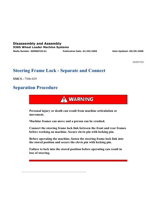
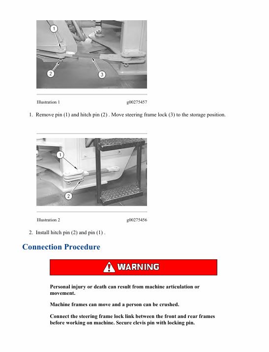
– Steering Frame Lock – Separate and Connect
– System Pressure – Release
– Turbocharger – Install
– Turbocharger – Remove
– Water Pump – Install
– Water Pump – Remove
– Water Temperature Regulator – Remove and Install
Disassembly and Assembly 930G Wheel Loader Machine Systems
– Blower Motor (Air Conditioner, Heater) – Remove and Install
– Brake Accumulator – Remove and Install
– Brake Control Valve (Service) – Remove and Install
– Bucket – Install
– Bucket – Remove
– Cab – Install
– Cab – Remove
– Counterweight – Install
– Counterweight – Remove
– Evaporator Coil – Remove and Install
– Gear Motor (Hydraulic Fan) – Assemble
– Gear Motor (Hydraulic Fan) – Disassemble
– Gear Motor (Hydraulic Fan) – Install
– Gear Motor (Hydraulic Fan) – Remove
– Gear Pump (Brake, Hydraulic Fan) – Assemble
– Gear Pump (Brake, Hydraulic Fan) – Disassemble
– Gear Pump (Brake, Hydraulic Fan) – Install
– Gear Pump (Brake, Hydraulic Fan) – Remove
– Heater Coil – Remove and Install
– Hydraulic Tank – Install
– Hydraulic Tank – Remove
– Kickout and Positioner – Remove and Install
– Lift Arms – Install
– Lift Arms – Remove
– Lift Cylinder – Remove and Install
– Loader Frame and Rear Frame – Connect
– Loader Frame and Rear Frame – Separate
– Main Control Valve – Assemble
– Main Control Valve – Disassemble
– Main Control Valve – Install
– Main Control Valve – Remove
– Metering Pump (HMU) – Install
– Metering Pump (HMU) – Remove
– Parking Brake – Install
– Parking Brake – Remove
– Pilot Oil Accumulator – Remove and Install
– Pilot Operated Hydraulic Control – Assemble
– Pilot Operated Hydraulic Control – Disassemble
– Pilot Operated Hydraulic Control – Install
– Pilot Operated Hydraulic Control – Remove
– Pin Coupler Cylinder – Remove and Install
– Piston Pump (Steering, Implement, Pilot) – Assemble
– Piston Pump (Steering, Implement, Pilot) – Disassemble
– Piston Pump (Steering, Implement, Pilot) – Install
– Piston Pump (Steering, Implement, Pilot) – Remove
– Pressure Reducing Valve – Remove and Install
– Quick Coupler – Install
– Quick Coupler – Remove
– Ride Control Accumulator – Remove and Install
– Ride Control Valve – Remove and Install
– Seat – Remove and Install
– Steering Cylinder – Remove and Install
– Steering Frame Lock – Separate and Connect
– Steering Wheel – Remove and Install
– System Pressure – Release
– Tilt Cylinder – Remove and Install
– Tilt Lever (Front) and Tilt Link (Front) – Install
– Tilt Lever (Front) and Tilt Link (Front) – Remove
– Tilt Lever (Rear) – Install
– Tilt Lever (Rear) – Remove
– Tilt Link (Rear) – Install
– Tilt Link (Rear) – Remove
– Window Wiper and Wiper Motor (Front) – Remove and Install
– Window Wiper and Wiper Motor (Rear) – Remove and Install
Disassembly and Assembly 930G Wheel Loader Power Train
– Axle Housing – Assemble
– Axle Housing – Disassemble
– Brake and Planetary – Remove and Install
– Bypass Valve (Power Train Oil Cooler) – Assemble
– Bypass Valve (Power Train Oil Cooler) – Disassemble
– Bypass Valve (Power Train Oil Cooler) – Install
– Bypass Valve (Power Train Oil Cooler) – Remove
– Differential – Assemble
– Differential – Disassemble
– Differential and Bevel Gear – Install
– Differential and Bevel Gear – Remove
– Differential Pinion (Front) – Assemble
– Differential Pinion (Front) – Disassemble
– Differential Pinion (Rear) – Assemble
– Differential Pinion (Rear) – Disassemble
– Drive Shaft – Remove and Install
– Duo-Cone Conventional Seals – Install
– Fixed Axle (Front) – Install
– Fixed Axle (Front) – Remove
– Limited Slip Differential – Assemble
– Limited Slip Differential – Disassemble
– NoSPIN Differential – Assemble
– NoSPIN Differential – Disassemble
– Oscillating Axle (Rear) – Install
– Oscillating Axle (Rear) – Remove
– Parking Brake – Remove and Install
– Power Train Guard (Transmission) – Remove and Install
– Steering Frame Lock – Separate and Connect
– System Pressure – Release
– Tire and Rim – Remove and Install
– Transmission and Torque Converter – Assemble
– Transmission and Torque Converter – Disassemble
– Transmission and Torque Converter – Install
– Transmission and Torque Converter – Remove
– Transmission Control Valve – Assemble
– Transmission Control Valve – Disassemble
– Transmission Control Valve – Install
– Transmission Control Valve – Remove
– Transmission Oil Pump – Assemble
– Transmission Oil Pump – Disassemble
– Transmission Oil Pump – Install
– Transmission Oil Pump – Remove
– Trunnion Support (Oscillating Axle, Front) – Remove and
– Trunnion Support (Oscillating Axle, Rear) – Remove and Install
MSS3s Machine Security System
– Cat Data Link – Test
– Connector Contact Description
– Connector Locations
– Data Links
– Determining Diagnostic Trouble Codes
– Diagnostic Capabilities
– Diagnostic Operation
– Diagnostic Trouble Codes
– ECM – Configure
– ECM – Replace
– ECM Output Driver – Test
– ECM Software – Install
– Electrical Connector – Inspect
– Electrical Power Supply – Test
– Electronic Control Module (ECM)
– Emerging Symptom Information
– Engine Does Not Crank and Status Indicator Is Green
– Engine Does Not Start and Status Indicator Is Continuously
– Events
– Factory Password – Obtain
– General Information
– General Information
– General Information
– Glossary of Terms
– Key – Program
– Key Information
– Lost Key (MSS)
– Machine Preparation for Troubleshooting
– Normal Operation
– Operation of Status Indicator
– Product Identification Number – Program
– Protected Functions
– Scheduled Access – “Security System Bypass Times”
– Service Operation Using Machine Security System
– Service Operation Using Service Tool
– Service Tools
– Software – Uninstall – “Immobilizer” Feature
– Symptom Troubleshooting
– System Components
– System Disarm – Program – Security System Bypass
– System Overview
– System Schematic
– Time – Set
– Visual Inspection
– Wiring Harness (Open Circuit) – Test
– Wiring Harness (Short Circuit) – Test
Machine Security System (MSS3i) Integrated
– System Overview
– System Components
– Data Link
– General Information
– Troubleshooting
– Key – Program
– Scheduled Access – Program – Security System Bypass
– Time – Set
– Factory Password – Obtain
– Configuration
– Machine Security System – Uninstall
– Normal Operation
– Glossary of Terms
– System Schematic
– Operation of Status Indicator
– Key Information
– Scheduled Access – “Security System Bypass Times”
– Diagnostic Operation
– Protected Functions
– Service Operation Using Service Tool
– Electronic Control Module (ECM)
– General Information
Machine Security System
– Cat Data Link
– Diagnostic Code List
– Diagnostic Operation
– Electrical Component and Connector Locations
– Electrical Connector – Inspect
– Electronic Control Module (ECM)
– Electronic Control Module (ECM) – Flash Program
– Electronic Control Module (ECM) – Replace
– Emerging Symptom Information
– Engine Does Not Crank and Status Indicator Is Green
– Engine Does Not Start and Status Indicator Is Continuously
– Events
– Factory Password – Obtain
– General Information
– General Information
– General Information
– Glossary of Terms
– Key – Program
– Key Information
– Lost Key
– MID 124 – CID 0168 – FMI 00
– MID 124 – CID 0168 – FMI 01
– MID 124 – CID 0248 – FMI 12
– MID 124 – CID 0817 – FMI 04
– MID 124 – CID 1391 – FMI 03
– MID 124 – CID 1391 – FMI 04
– MID 124 – CID 1392 – FMI 03
– MID 124 – CID 1392 – FMI 04
– Normal Operation
– Operation of Status Indicator
– Product Identification Number – Program
– Protected Functions
– Scheduled Access – “Security System Bypass Times”
– Service Operation Using Machine Security System
– Service Operation Using Service Tool
– Service Tools
– Software – Uninstall – “Immobilizer” Feature
– Symptom Troubleshooting
– System Components
– System Disarm – Program – Security System Bypass
– System Overview
– System Schematic
– Time – Set
– Using Caterpillar Electronic Technician to Determine
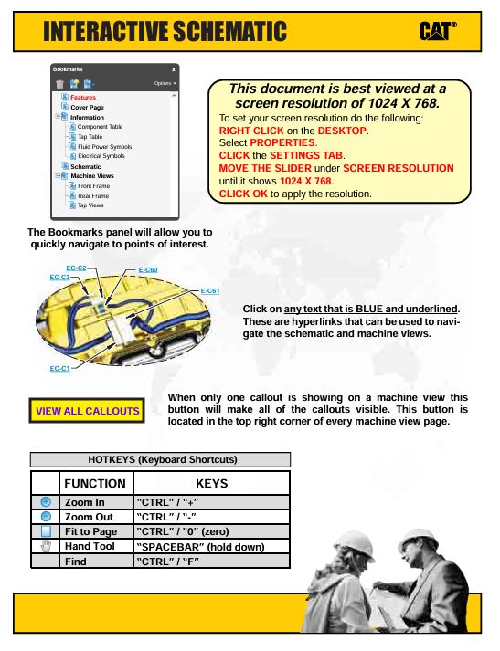
Schematic Caterpillar 924G & 924Gz Wheel Loader 928G Wheel Loader 930G Wheel Loader Electrical System
– Features
– Cover Page
– Information
– Component Location
– Volume 1 of 2 – Cab
– Volume 2 of 2 – Engine and Chassis
– Page 1 of 2
– Page 2 of 2
– Connector Location
– Volume 1 of 2 – Cab
– Volume 2 of 2 – Engine and Chassis
– CID / MID / FMI
– Specifications and Related Manuals
– Volume 1 of 2 – Cab
– Volume 2 of 2 – Engine and Chassis
– Standard Electrical
– Schematics
– Volume 1 of 2 – Cab
– Volume 2 of 2 – Engine and Chassis
– Machine View
– Machine Harness Connector and Component Locations
Schematic Caterpillar 930G Wheel Loader Hydraulic System
Specifications 3056E Engines for Caterpillar Built Machines
– Air Inlet Heater
– Alternator and Regulator
– Boost Pressure Sensor
– Camshaft
– Camshaft Bearings
– Connecting Rod
– Connecting Rod Bearing Journal
– Coolant Temperature Sensor
– Crankcase Breather
– Crankshaft
– Crankshaft Seals
– Cylinder Block
– Cylinder Head
– Cylinder Head Valves
– Cylinder Liner
– Electric Starting Motor
– Electronic Control Module
– Engine Design
– Engine Lifting Bracket
– Engine Oil Bypass Valve
– Engine Oil Cooler
– Engine Oil Filter Base
– Engine Oil Filter Bypass Valve
– Engine Oil Pan
– Engine Oil Pressure
– Engine Oil Pump
– Engine Oil Temperature Sensor
– Exhaust Manifold
– Flywheel
– Flywheel Housing
– Front Housing and Covers
– Fuel Filter Base
– Fuel Injection Lines
– Fuel Injection Nozzles
– Fuel Injection Pump
– Fuel Lines
– Fuel Priming Pump
– Gear Group (Front)
– Inlet Manifold
– Inlet Manifold Temperature Sensor
– Lifter Group
– Main Bearing Journal
– Piston and Rings
– Piston Cooling Jet
– Rocker Shaft
– Speed/Timing Sensor
– Turbocharger
– Valve Mechanism Cover
– Vibration Damper and Pulley
– Water Pump
– Water Temperature Regulator
– Water Temperature Regulator Housing
Specifications 930G Wheel Loader Hydraulic System
– Combination Valve
– Hydraulic Tank
– Lift Cylinder
– Main Control Valve (2-Function)
– Main Control Valve (3-Function)
– Main Control Valve (4-Function)
– Main Control Valve (Auxiliary) (5th, 6th Functions)
– Oil Filter (Hydraulic)
– Pilot Oil Accumulator
– Pilot Valve
– Pilot Valve
– Pilot Valve
– Pilot Valve (Joystick)
– Pilot Valve (Joystick)
– Pilot Valve (Joystick)
– Pilot Valve (Joystick)
– Pin Coupler Cylinder
– Piston Pump (Steering, Implement, Pilot)
– Pressure Reducing Valve
– Pressure Switch (Ride Control Disable)
– Quick Coupler Valve
– Ride Control Accumulator
– Ride Control Valve
– Solenoid Valve (Hydraulic Lockout)
– Temperature Sensor (Hydraulic Oil)
– Tilt Cylinder
– Work Tool Control
Specifications 930G Wheel Loader Power Train
– Axle Mounting
– Axle Oil Cooler Pump and Motor
– Bevel Gear and Pinion (Fixed Axle) (Oscillating Axle)
– Brake and Planetary
– Brake and Planetary
– Bypass Valve (Power Train Oil Cooler)
– Clutch (First, Third)
– Clutch (Forward High, Forward Low)
– Clutch (Reverse, Second)
– Differential
– Drive Shaft
– Engine and Transmission Mounting
– Fixed Axle Housing
– Limited Slip Differential
– Modulating Valve (Transmission Clutch)
– NoSPIN Differential
– Oil Filter (Power Train)
– Oscillating Axle Housing
– Pressure Switch (Axle Oil)
– Relief Valve (Transmission Hydraulic Control)
– Rim Mounting
– Speed Sensor (Torque Converter Output and Transmission
– Speed Sensor (Transmission Intermediate Output)
– Temperature Sensor (Torque Converter Oil)
– Temperature Sensor (Transmission Oil)
– Torque Converter
– Transmission
– Transmission Case
– Transmission Control Valve
– Transmission Output Gears
– Transmission Pump
Specifications 930G Wheel Loader Steering System
– Articulated Hitch
– Hydraulic Tank
– Magnetic Switch (Secondary Steering Relay)
– Metering Pump (HMU)
– Oil Filter (Hydraulic)
– Piston Pump (Steering, Implement, Pilot)
– Pressure Switch (Primary Steering Oil)
– Relief Valve (Secondary Steering)
– Secondary Steering Pump and Electric Motor
– Solenoid Valve (Quick Steer)
– Steering Control
– Steering Cylinder
– Steering Cylinder Mounting
Troubleshooting 3054E and 3056E Industrial Engines and Engines for Caterpillar Built Machines
– 5 Volt Engine Pressure Sensor Supply Circuit – Test
– Air Inlet Heater Circuit – Test
– Alternator Noise – Noisy Operation
– Alternator Will Not Charge – Charging Problem
– Analog Throttle Position Sensor Circuit – Test
– Battery
– CAN Data Link Circuit – Test
– Can Not Reach Top Engine RPM
– CID 0041 FMI 03
– CID 0041 FMI 04
– CID 0091 FMI 02
– CID 0091 FMI 03
– CID 0091 FMI 04
– CID 0091 FMI 08
– CID 0091 FMI 12
– CID 0100 FMI 03
– CID 0100 FMI 04
– CID 0100 FMI 10
– CID 0102 FMI 03
– CID 0102 FMI 04
– CID 0102 FMI 10
– CID 0105 FMI 03
– CID 0105 FMI 04
– CID 0110 FMI 03
– CID 0110 FMI 04
– CID 0174 FMI 02
– CID 0247 FMI 09
– CID 0253 FMI 02
– CID 0262 FMI 03
– CID 0262 FMI 04
– CID 0320 FMI 02
– CID 0320 FMI 11
– CID 0342 FMI 02
– CID 0774 FMI 02
– CID 0774 FMI 03
– CID 0774 FMI 04
– CID 0774 FMI 08
– CID 0774 FMI 12
– CID 1627 FMI 03
– CID 1684 FMI 00
– CID 1684 FMI 02
– CID 1684 FMI 03
– CID 1684 FMI 04
– CID 1684 FMI 05
– CID 1684 FMI 07
– CID 1684 FMI 08
– CID 1684 FMI 09
– CID 1684 FMI 10
– CID 1684 FMI 11
– CID 1684 FMI 12
– CID 1684 FMI 14
– CID 1743 FMI 02
– CID 1894 FMI 02
– CID 1895 FMI 02
– Coolant in Engine Oil
– Coolant Temperature Is Too High
– Data Link Circuit – Test
– Diagnostic Code Cross Reference
– Digital Throttle Position Sensor Circuit – Test
– E015 High Engine Coolant Temperature Derate
– E016 High Engine Coolant Temperature Shutdown
– E017 High Engine Coolant Temperature Warning
– E025 High Inlet Air Temperature Derate
– E027 High Inlet Air Temperature Warning
– E040 Low Engine Oil Pressure Shutdown
– E054 High Fuel Temperature Derate
– E056 High Fuel Temperature Warning
– E100 Low Engine Oil Pressure Warning
– E190 Engine Overspeed Warning
– ECM Will Not Accept Factory Passwords
– ECM Will Not Communicate with Other Systems or Display
– Electrical Connectors – Inspect
– Electrical Power Supply Circuit – Test
– Electronic Service Tool Will Not Communicate with ECM
– Electronic Service Tools
– Engine Cranks but Will Not Start
– Engine Has Early Wear
– Engine Misfires, Runs Rough or Is Unstable
– Engine Oil in Cooling System
– Engine Pressure Sensor Open or Short Circuit – Test
– Engine Stalls at Low RPM
– Engine Temperature Sensor Open or Short Circuit – Test
– Engine Vibration
– Engine Will Not Crank
– Engine Wiring Information
– Event Codes
– Excessive Black Smoke
– Excessive Engine Oil Consumption
– Excessive Valve Lash
– Excessive White Smoke
– Factory Passwords
– Flash Programming
– Fuel Injection Pump Circuit – Test
– Glossary
– Indicator Lamp Circuit – Test
– Indicator Lamps
– Intake Air Temperature Is Too High
– Intermittent Engine Shutdown
– Intermittent Low Power or Power Cutout
– Low Engine Oil Pressure
– Low Power/Poor or No Response to Throttle
– Mechanical Noise (Knock) in Engine
– Mode Selection Circuit – Test
– Noise Coming from Cylinder
– Programming Parameters
– Replacing the ECM
– Self-Diagnostics
– Sensors and Electrical Connectors
– Set Speed Circuit – Test
– Speed/Timing Sensor Circuit – Test
– System Configuration Parameters
– System Overview
– Throttle Switch Circuit – Test
Troubleshooting 930G Wheel Loader Machine Systems
– Backup Alarm Always Off
– Backup Alarm Always On
– Brake and Hydraulic Fan System
– Brake Oil Cooler Pressure
– Charging System
– Connector Contact Description
– Connector Locations
– Diagnostic Capabilities
– Diagnostic Code List
– Differential and Final Drive
– Electrical Connector – Inspect
– Electronic Control Module (ECM) – Flash Program
– Electronic Control Module (ECM) – Replace
– Emerging Symptom Information
– General Information
– Hydraulic System
– Machine Preparation for Troubleshooting
– MID 081 – CID 0041 – FMI 03
– MID 081 – CID 0041 – FMI 04
– MID 081 – CID 0070 – FMI 03
– MID 081 – CID 0070 – FMI 04
– MID 081 – CID 0096 – FMI 03
– MID 081 – CID 0096 – FMI 04
– MID 081 – CID 0096 – FMI 05
– MID 081 – CID 0168 – FMI 04
– MID 081 – CID 0177 – FMI 03
– MID 081 – CID 0177 – FMI 04
– MID 081 – CID 0177 – FMI 08
– MID 081 – CID 0247 – FMI 09
– MID 081 – CID 0262 – FMI 03
– MID 081 – CID 0262 – FMI 04
– MID 081 – CID 0271 – FMI 03
– MID 081 – CID 0271 – FMI 05
– MID 081 – CID 0271 – FMI 06
– MID 081 – CID 0291 – FMI 03
– MID 081 – CID 0291 – FMI 05
– MID 081 – CID 0291 – FMI 06
– MID 081 – CID 0367 – FMI 02
– MID 081 – CID 0367 – FMI 04
– MID 081 – CID 0368 – FMI 03
– MID 081 – CID 0368 – FMI 04
– MID 081 – CID 0420 – FMI 07
– MID 081 – CID 0426 – FMI 03
– MID 081 – CID 0426 – FMI 04
– MID 081 – CID 0426 – FMI 05
– MID 081 – CID 0444 – FMI 03
– MID 081 – CID 0444 – FMI 05
– MID 081 – CID 0444 – FMI 06
– MID 081 – CID 0473 – FMI 03
– MID 081 – CID 0473 – FMI 04
– MID 081 – CID 0473 – FMI 05
– MID 081 – CID 0486 – FMI 04
– MID 081 – CID 0490 – FMI 03
– MID 081 – CID 0490 – FMI 04
– MID 081 – CID 0585 – FMI 02
– MID 081 – CID 0590 – FMI 02
– MID 081 – CID 0590 – FMI 09
– MID 081 – CID 0590 – FMI 12
– MID 081 – CID 0600 – FMI 03
– MID 081 – CID 0600 – FMI 04
– MID 081 – CID 0600 – FMI 05
– MID 081 – CID 0637 – FMI 03
– MID 081 – CID 0637 – FMI 05
– MID 081 – CID 0637 – FMI 06
– MID 081 – CID 0668 – FMI 02
– MID 081 – CID 0672 – FMI 02
– MID 081 – CID 0673 – FMI 02
– MID 081 – CID 0674 – FMI 02
– MID 081 – CID 0675 – FMI 02
– MID 081 – CID 0747 – FMI 03
– MID 081 – CID 0747 – FMI 04
– MID 081 – CID 0793 – FMI 03
– MID 081 – CID 0793 – FMI 04
– MID 081 – CID 0811 – FMI 09
– MID 081 – CID 0826 – FMI 03
– MID 081 – CID 0826 – FMI 04
– MID 081 – CID 0826 – FMI 05
– MID 081 – CID 0882 – FMI 03
– MID 081 – CID 0882 – FMI 05
– MID 081 – CID 0882 – FMI 06
– MID 081 – CID 1231 – FMI 03
– MID 081 – CID 1231 – FMI 05
– MID 081 – CID 1231 – FMI 06
– MID 081 – CID 1251 – FMI 00
– MID 081 – CID 1251 – FMI 01
– MID 081 – CID 1251 – FMI 08
– MID 081 – CID 1401 – FMI 03
– MID 081 – CID 1401 – FMI 05
– MID 081 – CID 1401 – FMI 06
– MID 081 – CID 1402 – FMI 03
– MID 081 – CID 1402 – FMI 05
– MID 081 – CID 1402 – FMI 06
– MID 081 – CID 1403 – FMI 03
– MID 081 – CID 1403 – FMI 05
– MID 081 – CID 1403 – FMI 06
– MID 081 – CID 1404 – FMI 03
– MID 081 – CID 1404 – FMI 05
– MID 081 – CID 1404 – FMI 06
– MID 081 – CID 1405 – FMI 03
– MID 081 – CID 1405 – FMI 05
– MID 081 – CID 1405 – FMI 06
– MID 081 – CID 1406 – FMI 03
– MID 081 – CID 1406 – FMI 05
– MID 081 – CID 1406 – FMI 06
– MID 081 – CID 1639 – FMI 02
– MID 081 – CID 1639 – FMI 09
– MID 081 – CID 1834 – FMI 04
– MID 081 – CID 1960 – FMI 09
– MID 081 – CID 2292 – FMI 03
– MID 081 – CID 2292 – FMI 05
– MID 081 – CID 2292 – FMI 06
– Operational Checks (Brake, Hydraulic Fan System)
– Operational Checks (Hydraulic System)
– Operational Checks (Power Train)
– Operational Checks (Steering System)
– Service Tools
– Steering System
– Symptom Troubleshooting
– System Schematic
– Torque Converter
– Transmission
– Transmission Control (Shift Lever)
– Using Caterpillar Electronic Technician to Determine
– Using the Operator Monitor to Determine Diagnostic Codes
– Visual Inspection
– Wiring Harness (Open Circuit) – Test
– Wiring Harness (Short Circuit) – Test
Work Area Visual System
– Component Description
– Configuration
– Electrical Connector – Inspect
– General Information
– General Information
– Modes of Operation
– Service Tools
– System Schematic
– System Tests
– Troubleshooting
Service manual Caterpillar 930G Wheel Loader with 3056E Engine | TWR00001-UP
29,99 $
Format: PDF
Type: Service Manual
Pages: 4305
Size: 192 Mb
No.: TWR00001-UP
-
 Service manual Caterpillar D6R SERIES II TRACK-TYPE TRACTOR FTC XL with C-9 ENGINE | BPS00001-UP
29,99 $
ADD TO CART
Service manual Caterpillar D6R SERIES II TRACK-TYPE TRACTOR FTC XL with C-9 ENGINE | BPS00001-UP
29,99 $
ADD TO CART -
 Service manual Caterpillar D6M XL & D6M LGP TRACTORS / POWERSHIFT with 3116 ENGINE | 5NR00001-UP
29,99 $
ADD TO CART
Service manual Caterpillar D6M XL & D6M LGP TRACTORS / POWERSHIFT with 3116 ENGINE | 5NR00001-UP
29,99 $
ADD TO CART -
 Schematic Caterpillar 326 & 330 GC Excavator (Electrical System) | M0119281
9,99 $
ADD TO CART
Schematic Caterpillar 326 & 330 GC Excavator (Electrical System) | M0119281
9,99 $
ADD TO CART -
 Schematic Caterpillar 336D2 XE Excavator (Electrical System) | UENR5907-02
4,99 $
ADD TO CART
Schematic Caterpillar 336D2 XE Excavator (Electrical System) | UENR5907-02
4,99 $
ADD TO CART -
 Service manual Caterpillar 330F L Excavator with C7.1 Engine | GHT00001-UP
29,99 $
ADD TO CART
Service manual Caterpillar 330F L Excavator with C7.1 Engine | GHT00001-UP
29,99 $
ADD TO CART -
 Schematic Caterpillar 349E Excavator | UENR5393
9,99 $
ADD TO CART
Schematic Caterpillar 349E Excavator | UENR5393
9,99 $
ADD TO CART
Reviews
There are no reviews yet.