950M, 962M, 966M, 972M, 980M, and 982M Wheel Loaders Information Display
– CAN Data Link – Test
– Cat Data Link – Test
– Determining Diagnostic Trouble Codes
– Diagnostic Capabilities
– Diagnostic Trouble Codes
– Display Features
– Display Navigation
– Display Settings
– Electrical Power Supply – Test
– Event Codes
– False Detection Troubleshooting
– General Information
– Machine Parameters Menu
– Machine Settings Menu
– Menu Navigation
– Module – Flash Program
– Operator Menu
– Operator Profile Menu
– Pop-Up Messages
– Sensor (Data Link Type) – Test
– Sensor Supply – Test
– Service Menu
– Service Tools
– Symptom Troubleshooting
– System Schematic
– Totals Menu
966M and 972M Wheel Loaders Power Train, Steering, Braking, Hydraulic, and Machine Systems
– Articulated Hitch – Adjust
– Axle Oil Cooler – If Equipped
– Brake Accumulator
– Brake Accumulator – Test and Charge
– Brake Control Valve (Parking)
– Brake Control Valve (Service)
– Brake System Air – Purge
– Calibration Error Codes
– Calibrations (Cat ET)
– Calibrations (Graphical Display)
– Calibrations (Graphical Display)
– Control Manifold (Brake, Pilot, Fan)
– Control Manifold (Charging Valve for the Brake
– Differential (Locking)
– Differential (Open)
– Differential Backlash and Bearings – Adjust
– Differential Lock Pressure – Test
– Differential Pinion Preload – Adjust
– Electrohydraulic Control
– Electronic Control (Brake System)
– Electronic Control (Fan Hydraulic System)
– Electronic Control (HVAC System)
– Electronic Control (Hydraulic System)
– Electronic Control (Power Train System)
– Electronic Control (Steering System)
– Features (Electronic Control System)
– Fixed Axle (Front) and Oscillating Axle (Rear)
– General Information (Brake System)
– General Information (Electronic Control System)
– General Information (Fan Hydraulic System)
– General Information (HVAC System)
– General Information (Hydraulic System)
– General Information (Power Train System)
– General Information (Steering System)
– Glossary of Terms
– Graphic Color Codes
– Hydraulic Fan Speed – Test and Adjust
– Hydraulic Oil Contamination – Test
– Hydraulic Oil Cooler
– Hydraulic System
– Implement Cycle Time – Check
– Implement Hydraulic Service Mode
– Input Transfer Gear And Output Transfer Gear Lubrication
– Lift and Tilt Cylinder Drift – Check
– Limit Switch (Steering Control Position) – Test and Adjust
– Limit Switch (Stop Light) – Adjust
– Location of Components (Brake System)
– Location of Components (Fan Hydraulic System)
– Location of Components (HVAC System)
– Location of Components (Hydraulic System)
– Location of Components (Power Train System)
– Location of Components (Steering System)
– Machine Preparation for Troubleshooting
– Main Control Valve
– Modulating Valve (Torque Converter Lockup Clutch)
– Oil Coolers and Cooling System Operation
– Oil Filter (Power Train)
– Output Transfer Gears
– Output Transfer Gears – Adjust
– Parking Brake
– Parking Brake – Manual Release
– Parking Brake – Test
– Parking Brake – Test and Adjust – New Component Installation
– Pilot Oil Accumulator – Test and Charge
– Pilot Pressure – Test and Adjust
– Piston Motor (Hydraulic Fan)
– Piston Pump (Brake, Pilot, Fan)
– Piston Pump (Implement)
– Piston Pump (Implement) – Test and Adjust
– Piston Pump (Steering) High Pressure Stall – Test and Adjust
– Piston Pump (Steering) Margin Pressure – Test and Adjust
– Piston Pump Cutoff Pressure (Hydraulic Fan) – Test and Adjust
– Piston Pump Margin Pressure (Hydraulic Fan) – Test and
– Position Sensor (Left Brake Pedal)
– Position Sensor (Lift Linkage) – Replace
– Position Sensor (Steering Cylinder) – Set
– Position Sensor (Tilt Linkage) – Replace
– Pressure Limiter (Auxiliary Valve) – Check and Adjust
– Pressure Tap Locations
– Quick Coupler Pressure – Test and Adjust
– Quick Coupler System
– Relief Valve (Line)
– Relief Valve (Load Sensing Signal)
– Relief Valve (Pump Backup) – Test and Adjust
– Relief Valve – Test – Line
– Relief Valve – Test and Adjust – Steering Cylinder Work Port
– Ride Control Accumulator – Test and Charge
– Ride Control Activation Speed (Electronic Technician) – Adjust
– Ride Control System
– Secondary Steering Pump and Electric Motor
– Secondary Steering System
– Service Brake System Pressure – Test
– Service Brake Wear Indicator
– Service Brake Wear Indicator – Check
– Service Brakes
– Service Brakes – Test
– Steering Control – Control System
– Steering Control Valve
– Steering Pilot System
– Steering Pilot System Pressure – Test
– Steering Pump
– Steering Time – Check
– System Pressure – Release
– Tests (Cat ET)
– Torque Converter (Lockup)
– Torque Converter and Pump Drive Housing
– Transmission Hydraulic Control Operation
– Transmission Hydraulic System
– Transmission Lubrication
– Transmission Magnetic Screen
– Transmission Neutralizer Switch
– Transmission Oil Cooler
– Transmission Oil Pump
– Transmission Planetary
– Transmission Pressures – Test and Adjust
– Transmission Speed for Forward Directional Shift – Program
– Transmission Speed for Reverse Directional Shift – Program
– Variable Pitch Fan System
– Work Tool System
Air Conditioning and Heating R134a for All Cat Machines
– General Information
– Refrigerant Orifice Tube System
– Refrigerant Compressor
– Refrigerant Compressor
– Refrigerant Compressor
– Refrigerant Condenser
– Refrigerant Condenser
– Refrigerant Receiver-Dryer
– Refrigerant Receiver-Dryer
– Refrigerant Expansion Valve
– In-line Refrigerant Dryer
– Identifying the Refrigerant
– In-line Refrigerant Dryer
– Refrigerant Orifice Tube Assembly
– Refrigerant Orifice Tube Assembly
– Evaporator Coil
– Refrigerant Accumulator
– Refrigerant Accumulator
– Refrigerant Accumulator
– Refrigerant Compressor Protection System
– Temperature Control
– Temperature Control
– Identifying the Refrigerant
– Pressure Switch (Refrigerant)
– Pressure Switch (Refrigerant)
– Cab Pressurization and Filtration System
– Cab Pressurization and Filtration System
– Cab Pressurization and Filtration System
– Condensate Drainage System
– Condensate Drainage System
– Service Intervals
– Service Intervals
– Glossary of Terms
– Identifying the Air Conditioning System
– General Troubleshooting Information
– General Troubleshooting Information
– Machine Preparation for Testing and Adjusting
– Machine Preparation for Testing and Adjusting
– Air Conditioning Performance – Test
– Refrigerant Leakage – Test
– Manifold Gauge Set (Refrigerant) – Install
– Manifold Gauge Set (Refrigerant) – Install
– Refrigerant Recovery
– Refrigerant Recovery
– Identifying the Air Conditioning System
– Refrigerant System – Flush
– Refrigerant Oil – Test
– Refrigerant Compressor – Test
– Refrigerant Compressor – Test
– Refrigerant Compressor – Test
– Refrigerant System – Evacuate
– Refrigerant System – Evacuate
– Refrigerant System – Charge
– Refrigerant System – Charge
– Manifold Gauge Set (Refrigerant) – Remove
– Identifying the Heating System
– Manifold Gauge Set (Refrigerant) – Remove
– Compressor Protection System – Test
– Compressor Protection System – Test
– Electronic Heat Control – Test
– Electronic Heat Control – Test
– Heater Performance – Test
– Heating and Air Conditioning Service Publications
– General Information
– General Information
– Machine Preparation for Disassembly and Assembly
– Refrigerant Expansion Valve System
– Air Conditioner Lines – Remove and Install
– Refrigerant Compressor – Remove and Install
– Refrigerant Accumulator – Remove and Install
– Refrigerant Expansion Valve – Remove and Install
– Refrigerant Receiver-Dryer – Remove and Install
– In-Line Refrigerant Dryer – Remove and Install
– Refrigerant Orifice Tube Assembly – Remove and Install
– Refrigerant Expansion Valve System
– Refrigerant Orifice Tube System
– General Information
Cat Autolube System for Medium Wheel Loaders
– Automatic Lubrication System – Charge
– Automatic Lubrication System – Flush
– Automatic Lubrication System – Test
– Automatic Lubrication System Troubleshooting
– General Information
– Lubrication Distribution Valve
– Lubrication Pump
– System Pressure – Release
Cat Payload Kit For Medium Wheel Loaders
– Editing Truck and Material Lists
– General Information (Calibration)
– Menu Navigation
– Normal Weighing Operation
– Reweigh Operation
– Scale System
– Service Menu
– Simple Calibration
– Software – Install
– Totals Menu
– Troubleshooting
– Zero Operation
Disassembly and Assembly 966M Tier 4 and 972M Tier 4 Wheel Loaders Power Train
– Axle Housing – Assemble
– Axle Housing – Disassemble
– Carrier Bearing (Drive Shaft) – Remove and Install
– Differential (Locking) – Assemble
– Differential (Locking) – Disassemble
– Differential – Assemble
– Differential – Disassemble
– Differential and Bevel Gear – Remove and Install
– Differential Pinion – Assemble
– Differential Pinion – Disassemble
– Drive Shaft (Center) – Remove and Install
– Drive Shaft (Front) – Remove and Install
– Drive Shaft (Rear) – Remove and Install
– Duo-Cone Conventional Seals – Install
– Fixed Axle (Front) – Remove and Install
– Modulating Valve (Torque Converter Lockup Clutch) –
– Modulating Valve (Transmission Clutch) – Remove and Install
– Oscillating Axle (Rear) – Remove and Install
– Output Transfer Gears – Assemble
– Output Transfer Gears – Disassemble
– Parking Brake – Assemble
– Parking Brake – Disassemble
– Parking Brake – Remove and Install
– Power Train Guard (Transmission) – Remove and Install
– Power Train Guard (Transmission) – Remove and Install
– Pump and Motor – Assemble – Variator
– Pump and Motor – Disassemble – Variator
– Relief Valve (Torque Converter Outlet) – Remove and Install
– Relief Valve (Transmission Hydraulic Control) – Remove and
– Service Brakes – Remove and Install
– Steering Frame Lock – Separate and Connect
– System Pressure – Release
– Tire and Rim (Front) – Remove and Install
– Tire and Rim (Rear) – Remove and Install
– Torque Converter (Freewheel Stator) (Lockup) – Assemble
– Torque Converter (Freewheel Stator) (Lockup) – Disassemble
– Torque Converter from Transmission, Output Transfer Gears –
– Torque Converter to Transmission, Output Transfer Gears –
– Torque Converter, Transmission and Output Transfer Gears –
– Transmission from Output Transfer Gears – Separate
– Transmission Oil Cooler – Remove and Install
– Transmission Oil Filter Base – Assemble
– Transmission Oil Filter Base – Disassemble
– Transmission Oil Filter Base – Remove and Install
– Transmission Oil Pump – Assemble – Gear Pump – Charge
– Transmission Oil Pump – Disassemble – Gear Pump – Charge
– Transmission Oil Pump – Remove and Install – Gear Pump
– Transmission Planetary – Assemble
– Transmission Planetary – Assemble
– Transmission Planetary – Disassemble
– Transmission Planetary – Disassemble
– Transmission to Output Transfer Gears – Connect
– Trunnion Support (Oscillating Axle, Front) – Remove and
– Trunnion Support (Oscillating Axle, Rear) – Remove and Install
Disassembly and Assembly 966M Tier 4, 966M Tier 4 Series XE, 972M Tier 4 and 972M Tier 4 Series XE Wheel Loaders
– Aftercooler Core – Remove and Install
– Air Cleaner – Remove and Install
– Air Control Valve – Remove and Install
– Alternator – Remove and Install
– Batteries – Remove and Install
– Belt Tensioner – Remove and Install
– Catalyst – Remove and Install
– Clean Emissions Module – Remove and Install
– Combustion Head – Remove and Install – Clean Emissions
– Cooling System Package (Radiator, Fan, Aftercooler, Oil
– Cooling System Package (Radiator, Fan, Aftercooler, Oil
– Diesel Exhaust Fluid Injector – Remove and Install
– Diesel Exhaust Fluid Module – Assemble
– Diesel Exhaust Fluid Module – Assemble
– Diesel Exhaust Fluid Module – Disassemble
– Diesel Exhaust Fluid Module – Disassemble
– Diesel Exhaust Fluid Module – Remove and Install
– Diesel Particulate Filter – Remove and Install
– Electric Starting Motor – Remove and Install
– Engine – Remove and Install
– Engine and Transmission – Remove and Install
– Engine Oil Filter, Oil Filter Base and Oil Cooler – Remove and
– Engine Oil Filter, Oil Filter Base and Oil Cooler – Remove and
– Exhaust Elbow – Remove and Install
– Exhaust Lines – Remove and Install
– Fan Group (Includes Fan, Fan Guard, Fan Shroud, and
– Fuel Cooler – Remove and Install
– Fuel Filter (Secondary) and Fuel Filter Base – Remove and
– Fuel Filter (Secondary) and Fuel Filter Base – Remove and
– Fuel Level Sensor – Remove and Install
– Fuel Manifold – Remove and Install
– Fuel Manifold – Remove and Install – Clean Emissions Module
– Fuel Manifold – Remove and Install – Return
– Fuel Priming Pump – Assemble
– Fuel Priming Pump – Disassemble
– Fuel Priming Pump and Primary Filter (Water Separator) –
– Fuel Tank – Remove and Install
– Hood – Remove and Install
– Hood – Remove and Install – One Piece Hood
– Hood Tilt Actuator – Remove and Install
– Hood Tilt Actuator – Remove and Install – Smart Actuator
– Hydraulic Oil Cooler – Remove and Install
– Hydraulic Tank Oil – Retain
– Ignition Coil – Remove and Install
– Nozzle Heater Harness – Remove and Install
– Oil Pan – Remove and Install – In Chassis
– Pressure Sensor (ARD Combustion Air) – Remove and Install
– Pressure Sensor (DPF) – Remove and Install
– Radiator – Remove and Install
– Radiator Top Tank – Remove and Install
– Refrigerant Compressor – Remove and Install
– Refrigerant Condenser – Remove and Install
– Relay (ARD Nozzle Heater) – Remove and Install
– Steering Frame Lock – Separate and Connect
– System Pressure – Release
– Temperature Sensor (DPF) – Remove and Install
– Turbocharger – Remove and Install
– Turbocharger – Remove and Install – Cooled by Coolant
– Valve Cover – Remove and Install
– Vibration Damper and Pulley – Remove and Install
– Water Pump – Remove and Install
Disassembly and Assembly 966M Tier 4, 966M Tier 4 Series XE, 972M Tier 4 and 972M Tier 4 Series XE Wheel Loaders
– Accumulator (Steering, Pilot) – Remove and Install
– Blower Motor (Air Conditioner and Heater) – Remove and
– Brake Accumulator – Assemble
– Brake Accumulator – Disassemble
– Brake Accumulator – Remove and Install
– Brake Control Valve (Parking) – Assemble
– Brake Control Valve (Parking) – Disassemble
– Brake Control Valve (Parking) – Remove and Install
– Brake Control Valve (Service) – Assemble
– Brake Control Valve (Service) – Disassemble
– Brake Control Valve (Service) – Remove and Install
– Bucket – Remove and Install
– Cab – Remove and Install
– Combination Valve (Brake Accumulator Charge, Fan Supply,
– Combination Valve (Brake Accumulator Charge, Fan Supply,
– Combination Valve (Brake Accumulator Charge, Fan Supply,
– Control Valve (Auxiliary) – Assemble
– Control Valve (Auxiliary) – Disassemble
– Control Valve (Auxiliary) – Remove and Install
– Differential Lock Valve – Assemble – Front Axle Differential
– Differential Lock Valve – Assemble – Rear Axle Differential
– Differential Lock Valve – Disassemble – Front Axle Differential
– Differential Lock Valve – Disassemble – Rear Axle Differential
– Differential Lock Valve – Remove and Install – Front Axle
– Differential Lock Valve – Remove and Install – Rear Axle
– Electrohydraulic Steering Control (Joystick) – Remove and
– Evaporator Coil and Heater Coil – Remove and Install
– Gear Pump (Secondary Steering) – Assemble
– Gear Pump (Secondary Steering) – Disassemble
– Handle (Joystick) – Remove and Install
– Hydraulic Tank – Assemble
– Hydraulic Tank – Disassemble
– Hydraulic Tank – Remove and Install
– Hydraulic Tank Oil – Retain
– Instrument Panel (Lower) – Remove and Install
– Instrument Panel (Upper) – Remove and Install
– Lift Arms – Remove and Install
– Lift Arms – Remove and Install
– Lift Cylinder – Remove and Install
– Lift Position Sensor and Mounting (Lift Kickout Control) –
– Loader Frame from Rear Frame – Separate
– Loader Frame to Rear Frame – Connect
– Lubrication Pump (Automatic) – Assemble
– Lubrication Pump (Automatic) – Disassemble
– Lubrication Pump (Automatic) – Remove and Install
– Main Control Valve – Assemble
– Main Control Valve – Disassemble
– Main Control Valve and Mounting Plate – Remove and Install
– Manual Valve – Remove and Install
– Oil Filter (Brake, Hydraulic Fan) – Remove and Install
– Pilot Oil Accumulator (Dead Engine Lower) – Remove and
– Piston Pump (Brake, Pilot, Fan) – Assemble
– Piston Pump (Brake, Pilot, Fan) – Disassemble
– Piston Pump (Brake, Pilot, Fan) – Remove and Install
– Piston Pump (Implement) – Assemble
– Piston Pump (Implement) – Assemble
– Piston Pump (Implement) – Assemble
– Piston Pump (Implement) – Assemble – 165 cc
– Piston Pump (Implement) – Assemble – 45 cc
– Piston Pump (Implement) – Disassemble
– Piston Pump (Implement) – Disassemble
– Piston Pump (Implement) – Disassemble – 165 cc
– Piston Pump (Implement) – Disassemble – 45 cc
– Piston Pump (Implement) – Remove and Install
– Piston Pump (Implement) – Remove and Install – 165 CC
– Piston Pump (Implement) – Remove and Install – 45 CC
– Piston Pump (Steering) – Assemble
– Piston Pump (Steering) – Disassemble
– Piston Pump (Steering) – Remove and Install
– Piston Pump (Steering) – Remove and Install
– Precleaner – Remove and Install – HVAC
– Quick Coupler – Remove and Install
– Refrigerant Receiver-Dryer – Remove and Install
– Ride Control Accumulator – Remove and Install
– Seat – Remove and Install
– Secondary Steering Pump and Electric Motor – Remove and
– Secondary Steering Valve – Assemble
– Secondary Steering Valve – Disassemble
– Secondary Steering Valve – Remove and Install
– Steering Cylinder – Remove and Install
– Steering Frame Lock – Separate and Connect
– Steering Valve – Assemble
– Steering Valve – Disassemble
– Steering Valve – Remove and Install
– System Pressure – Release
– Tilt Cylinder – Remove and Install
– Tilt Lever – Remove and Install
– Tilt Link – Remove and Install
– Tilt Position Sensor and Mounting (Worktool Positioner
– Window Wiper and Wiper Motor (Front) – Remove and Install
– Window Wiper and Wiper Motor (Rear) – Remove and Install
Disassembly and Assembly C9.3 Engines for Caterpillar Built Machines
– Air Compressor – Remove and Install
– Air Control Valve – Remove and Install
– Atmospheric Pressure Sensor – Remove and Install
– Bearing Clearance – Check
– Belt Tensioner – Remove and Install
– Camshaft – Remove and Install
– Camshaft Bearings – Remove and Install
– Camshaft Gear – Remove and Install
– Catalyst (SCR) – Remove and Install
– Clean Emissions Module – Remove and Install
– Combustion Head – Remove and Install – Clean Emissions
– Compression Brake – Assemble – Valve Assembly
– Compression Brake – Disassemble – Valve Assembly
– Compression Brake – Remove and Install
– Connecting Rod Bearings – Remove and Install
– Coolant Temperature Sensor – Remove and Install
– Crankcase Pressure Sensor – Remove and Install
– Crankshaft – Remove and Install
– Crankshaft Front Seal – Remove and Install
– Crankshaft Main Bearings – Remove and Install
– Crankshaft Rear Seal – Remove and Install
– Cylinder Block Cover – Remove and Install
– Cylinder Head – Install
– Cylinder Head – Remove
– Cylinder Liner – Remove and Install
– DEF Injector and Mounting – Remove and Install
– Diesel Exhaust Fluid Filter – Remove and Install
– Diesel Exhaust Fluid Module – Assemble
– Diesel Exhaust Fluid Module – Disassemble
– Diesel Exhaust Fluid Pump – Remove and Install
– Diesel Particulate Filter – Remove and Install
– Disconnecting Snap To Connect Fittings
– Electric Starting Motor – Remove and Install
– Electronic Control (Diesel Exhaust Fluid) – Remove and Install
– Engine Control Module – Remove and Install
– Engine Oil Cooler – Remove and Install
– Engine Oil Filter Base – Remove and Install
– Engine Oil Pan – Remove and Install
– Engine Oil Pressure Sensor – Remove and Install
– Engine Oil Pump – Remove and Install
– Exhaust Cooler (NRS) – Remove and Install
– Exhaust Elbow – Remove and Install
– Exhaust Gas Valve (NRS) – Assemble
– Exhaust Gas Valve (NRS) – Disassemble
– Exhaust Gas Valve (NRS) – Remove and Install
– Exhaust Manifold – Remove and Install
– Fan Drive Mounting Group – Remove and Install
– Flywheel – Remove and Install
– Flywheel Housing – Remove and Install
– Front Cover – Remove and Install
– Fuel Filter Base – Remove and Install
– Fuel Injection Pump – Remove and Install
– Fuel Lines – Remove and Install
– Fuel Manifold (Rail) – Remove and Install
– Fuel Manifold – Remove and Install
– Fuel Manifold – Remove and Install – Return
– Fuel Pressure Sensor – Remove and Install – Rail
– Fuel Priming Pump – Remove and Install
– Fuel Transfer Pump – Remove and Install
– Fumes Disposal Filter – Remove and Install
– Housing (Front) – Remove and Install
– Ignition Coil – Remove and Install
– Inlet and Exhaust Valve Guides – Remove and Install
– Inlet and Exhaust Valve Seat Inserts – Remove and Install
– Inlet and Exhaust Valves – Remove and Install
– Inlet Manifold – Remove and Install
– Inlet Manifold Pressure Sensor – Remove and Install
– Inlet Manifold Temperature Sensor – Remove and Install
– Inlet Module (Catalyst) – Remove and Install
– Lifter Group – Remove and Install
– Manifold (DEF Heater) – Remove and Install
– Nitrogen Oxide Sensor – Remove and Install
– Nozzle Heater Harness – Remove and Install
– Piston Cooling Jets – Remove and Install
– Pistons and Connecting Rods – Assemble – Symmetrical
– Pistons and Connecting Rods – Disassemble
– Pistons and Connecting Rods – Install
– Pistons and Connecting Rods – Remove
– Pressure Sensor (ARD Combustion Air) – Remove and Install
– Pressure Sensor (DPF) – Remove and Install
– Pressure Sensor (NRS Absolute) – Remove and Install
– Pressure Sensor (NRS Differential) – Remove and Install
– Rear Power Take-Off (RPTO) – Install
– Rear Power Take-Off (RPTO) – Remove
– Relay (ARD Nozzle Heater) – Remove and Install
– Relief Valve (Fuel) – Remove and Install
– Rocker Arm – Assemble
– Rocker Arm – Disassemble
– Rocker Arm and Shaft – Remove and Install
– Solenoid Valve (ARD Fuel) – Remove and Install
– Solenoid Valve (DEF Heater Coolant) – Remove and Install
– Solenoid Valve (Exhaust Balance) – Remove and Install
– Speed/Timing Sensor – Remove and Install
– Temperature Sensor (Catalyst Inlet) – Remove and Install
– Temperature Sensor (DPF Inlet, Flame Detect) – Remove and
– Turbocharger – Remove and Install – Cooled by Coolant
– Unit Injector – Remove and Install
– Unit Injector Sleeve – Remove and Install
– Valve Mechanism Cover – Remove and Install
– Venturi Tube – Remove and Install
– Vibration Damper and Pulley – Remove and Install
– Voltage Control (Load Protection) – Remove and Install
– Water Pump – Assemble
– Water Pump – Disassemble
– Water Pump – Remove and Install
– Water Temperature Regulator – Remove and Install
Medium L and M Series Wheel Loaders Cat Production Measurement Application on Machines Equipped with Product Link
– Automatic Material Identification
– Automatic Truck Identification
– Calibration Using Display Module
– Calibration Using Electronic Service Tool
– Calibration Weight Entering
– Cat ET List Management
– Configuration – Product Link Web Configuration
– Display Modules
– Editing Truck and Material Lists
– General Information (Calibration)
– Menu Navigation
– Normal Weighing Operation
– Payload Menu
– Reweigh Operation
– Scale System
– Service Menu
– Service Tool Software
– Simple Calibration
– Software – Install
– System Schematic
– Totals Menu
– Troubleshooting
– VIMSpc Payload Reports
– VIMSpc Software
– Weigh Range Adjusting
– Zero Operation
Schematic Caterpillar 966L, 966M, 972L, and 972M Wheel Loader Power Train Oil System
– Features
– Cover Page
– Information
– Component Location
– Tap Location
– Schematic
– Machine Views
– Left Side View
– Right Side View
Schematic Caterpillar 966M and 972M Wheel Loader Cooling System
– Features
– Cover Page
– Information
– Component Location
– Schematic
– Machine Views
– Machine Left View
– Machine Right View
Schematic Caterpillar 966M and 972M Wheel Loader Hydraulic System
– Features
– Cover Page
– Information
– Component Location
– Page 1 of 2
– Page 2 of 2
– Tap Location
– Schematic
– Machine Views
– Implement and Aux Valves View 1
– Implement and Aux Valves View 2
– Machine Views
– Right Side Views
Schematic Caterpillar 966M, 966M XE, 972M and 972M XE Wheel Loader Electrical System
– Feature
– Cover Page
– Information
– Component Location
– Cab
– Chassis Wiring
– Engine Wiring
– Aftertreatment Next Gen (If Equipped)
– Connector Location
– Cab
– Chassis Wiring
– Engine Wiring
– Aftertreatment Next Gen (If Equipped)
– Schematics
– Cab
– Chassis Wiring
– Engine Wiring
– Aftertreatment Next Gen (If Equipped)
– Machine Views
– Cab
– Cab Front Console
– Cab Left View
– Cab Rear View
– Cab Rear Wall
– Fuse Block
– HVAC Unit
– Implement Joystick
– Operator Console
– Chassis
– Batteries
– Compartment View
– CVT Transmission
– Engine View
– Front and Rear Axle
– Front Frame
– Hydraulic Service Center
– Implement Aux Valve
– LH Chassis View
– Powershift Transmission
– Engine Wiring
– CEM
– LH Engine View
– Pump Tank Unit
– RH Engine View
– Aftertreatment Next Gen (If Equipped)
– Pump Tank Unit
Schematic Caterpillar 966M, 966M XE, 972M and 972M XE Wheel Loader Electrical System
– Feature
– Cover Page
– Information
– Component Location
– Vol 1 – Cab
– Vol 2 – Chassis Wiring
– Page 1 of 2
– Page 2 of 2
– Vol 3 – Engine Wiring
– Vol 4 – Aftertreatment Nect Gen (If Equipped)
– Connector Location
– Vol 1 – Cab
– Vol 2 – Chassis Wiring
– Vol 3 – Engine Wiring
– Vol 4 – Aftertreatment Nect Gen (If Equipped)
– Schematics
– Function Isolation Tools
– Grids On/Off
– All Circuits Off
– All Circuits On
– Vol 1 – Cab
– Unspecified Circuit
– Black (Ground)
– 032 (Red) (Battery Power)
– 640 (Blue) (Key Power)
– 305 (Lt Blue) (Converter 12v Out)
– 021 (Orange) (Starting)
– 258 (Dk Purple) (Xmsn/Machine/Engine Pump)
– 430 (Dk Gray) (Machine Security)
– 509 (Lt Pink) (Engine Control)
– 613 (Dk Yellow) (Heat/AC)
– 4665 (Tan) (Turn/Wiper/Washer)
– CON 346 (CAT D.L.)
– CON 032 (RS232/485 D.L.)
– SUB 141 (Lt Orange) (Impl/Valve/Tool)
– CON 190 (CAN “A” D.L.)
– CON 522 (CAN “B” D.L.)
– SUB 522 (Lt Purple) (Aftertreatment)
– SUB 651 (Blue Gray) (Ethernet)
– Vol 2 – Chassis Wiring
– Unspecified Circuit
– Black (Ground)
– 032 (Red) (Battery Power)
– 640 (Blue) (Key Power)
– 305 (Lt Blue) (Converter 12v Out)
– 021 (Orange) (Starting)
– 190 (Dk Pink) (Start Aid)
– 258 (Dk Purple) (Xmsn/Machine/Engine Pump)
– 509 (Lt Pink) (Engine Control)
– 613 (Dk Yellow) (Heat/AC)
– 4665 (Tan) (Turn/Wiper/Washer)
– CON 346 (CAT D.L.)
– SUB 141 (Lt Orange) (Impl/Valve/Tool)
– CON 190 (CAN “A” D.L.)
– CON 522 (CAN “B” D.L.)
– CON 141 (CAN “C” D.L.)
– CON 5767 (Olive Green) (DEF)
– SUB 522 (Lt Purple) (Aftertreatment)
– Vol 3 – Engine Wiring
– Unspecified Circuit
– Black (Ground)
– 032 (Red) (Battery Power)
– 640 (Blue) (Key Power)
– 509 (Lt Pink) (Engine Control)
– CON 190 (CAN “A” D.L.)
– CON 522 (CAN “B” D.L.)
– CON 141 (CAN “C” D.L.)
– CON 5767 (Olive Green) (DEF)
– SUB 522 (Lt Purple) (Aftertreatment)
– Vol 4 – Aftertreatment Nect Gen (If Equipped)
– Unspecified Circuit
– Black (Ground)
– 032 (Red) (Battery Power)
– 640 (Blue) (Key Power)
– CON 190 (CAN “A” D.L.)
– CON 141 (CAN “C” D.L.)
– SUB 522 (Lt Purple) (Aftertreatment)
– SUB 577 (Lt Green) (Payload)
– Machine Views
– Vol 1 – Cab
– Cab Front View
– Implement Joystick View
– Operator Seat And Control View
– Rear Cab Side View
– Rear Cab Wall View
– RH Console
– Vol 2 – Chassis Wiring
– Batteries
– Compartment View
– CVT Transmission
– Engine View
– Front And Rear Axle
– Front Frame
– Hydraulic Service Center
– Implement AUX Valve
– LH Chassis View
– Powershift Transmission
– Vol 3 – Engine Wiring
– CEM
– LH Engine View
– Pump Tank Unit
– RH Engine View
– Vol 4 – Aftertreatment Nect Gen (If Equipped)
– Pump Tank Unit
Specifications 966M and 972M Wheel Loaders Power Train, Steering, Braking, Hydraulic & Machine Systems
– Accumulator (Hydraulic)
– Accumulator (Pilot Oil)
– Accumulator (Steering)
– Accumulator (Steering)
– Accumulator Charging Valve
– Accumulator Charging Valve – Brake Accumulator Charge,
– Air Cleaner
– Air Cleaner
– Air Cleaner
– Air Cleaner – CAP
– Air Cleaner – CAP
– Air Cleaner – Mounting
– Air Conditioner – Mounting
– Air Conditioner – Mounting
– Air Conditioner Lines
– Air Lines
– Air Lines
– Antenna
– Articulating Hitch
– Articulating Hitch
– Axle Mounting
– Axle Mounting
– Bevel Gear and Pinion (Fixed Axle)
– Bevel Gear and Pinion (Fixed Axle)
– Bevel Gear and Pinion (Oscillating Axle)
– Bevel Gear and Pinion (Oscillating Axle)
– Bevel Gear and Pinion (Oscillating Axle)
– Bevel Gear and Pinion (Oscillating Axle)
– Bevel Gear and Pinion (Oscillating Axle)
– Bevel Gear and Pinion (Oscillating Axle)
– Brake Accumulator
– Brake Accumulator
– Brake and Hydraulic Fan Pump and Mounting
– Brake and Hydraulic Fan Pump and Mounting
– Brake and Planetary
– Brake and Planetary
– Breather (Hydraulic Tank)
– Bucket
– Bucket
– Bucket – Material Handling
– Bucket – Material Handling
– Bucket – Multipurpose
– Bucket – Side Dump
– Bucket Cylinder
– Bucket Cylinder
– Bucket Cylinder
– Cab – Door Left Hand
– Cab – Door Left Hand
– Cab – Door Left Hand
– Cab – Door Right Hand
– Cab – Door Right Hand
– Cab – Mounting
– Cab – Roof
– Cab – Trim Group
– Cab Air Duct – Filter
– Cab Liner
– Cab Window
– Check and Relief Valve
– Check Valve (Brake Accumulator)
– Check Valve (Brake Accumulator)
– Check Valve (Pilot)
– Check Valve (Steering Quad)
– Check Valve (Steering Quad)
– Control (Autodig)
– Control (Autodig)
– Control Manifold
– Control Manifold (Axle Oil Flow Divider)
– Control Manifold (Axle Oil Flow Divider)
– Control Manifold (Steering)
– Control Manifold (Steering)
– Control Valve (Auxiliary)
– Control Valve (Auxiliary)
– Control Valve (Auxiliary)
– Control Valve and Mounting
– Control Valve and Mounting
– Control Valve and Mounting
– Counterweight
– Counterweight
– Coupler Cylinder – Quick Coupler
– Coupler Cylinder – Quick Coupler
– Coupler Lines
– Cutting Edges, End Bits and Teeth
– Cutting Edges, End Bits and Teeth
– Cutting Edges, End Bits and Teeth
– Cutting Edges, End Bits and Teeth
– Cutting Edges, End Bits and Teeth
– Cutting Edges, End Bits and Teeth
– Cutting Edges, End Bits and Teeth
– Demand Fan Valve
– Demand Fan Valve
– Differential (Locking)
– Differential (Locking)
– Differential (Standard)
– Differential (Standard)
– Differential Lock Control
– Differential Lock Control
– Drive Shaft
– Drive Shaft
– Dust Ejector
– Electric Starting Motor
– Electrohydraulic Control
– Electrohydraulic Control (Joystick)
– Electrohydraulic Control – Control Adjuster Group
– Electrohydraulic Control – Mounting
– Electrohydraulic Control – Mounting
– Electrohydraulic Control – Mounting
– Electrohydraulic Control – Mounting
– Electrohydraulic Control – Support
– Electronic Control Module
– Electronic Control Module
– Electronic Control Module
– Electronic Control Module
– Electronic Control Module – Mounting
– Engine and Transmission Mounting
– Engine Compartment Shield
– Engine Compartment Shield
– Engine Support
– Exhaust Lines
– Fender
– Fender
– Fender
– Fender
– Fender
– Fender
– Fender
– Fender
– Fixed Axle Housing (Front)
– Fixed Axle Housing (Front)
– Flood Lamp
– Flood Lamp
– Flood Lamp
– Flood Lamp
– Foot Switch (Differential Lock)
– Front Guard
– Front Guard
– Fuel Lines
– Fuel Lines
– Fuel Tank
– Fuel Tank
– Fuel Tank
– Fuel Tank
– Gear Pump (Secondary Steering)
– Gear Pump (Secondary Steering)
– Governor Pedal
– Governor Pedal
– Hood
– Hood – Guard
– Hydraulic Oil Cooler – Lines Group
– Hydraulic Tank
– Hydraulic Tank
– Implement Control – Mounting
– Instrument Panel
– Joystick Control
– Joystick Control
– Joystick Control
– Left Hand Steering Control
– Left Hand Steering Control
– Left Hand Steering Control
– Left Hand Steering Control
– Lift Arm
– Lift Arm
– Lift Cylinder
– Lift Cylinder
– Lift Cylinder
– Lift Cylinder
– Lines (Axle Oil Cooler)
– Lines (Axle Oil Cooler)
– Lines (Axle Oil Cooler)
– Lines (Axle Oil Cooler)
– Lines (Diagnostic)
– Lines (Diagnostic)
– Lubrication Pump
– Lubrication Pump
– Main Control Valve
– Main Control Valve
– Main Control Valve
– Main Control Valve
– Main Control Valve and Mounting
– Main Control Valve and Mounting
– Main Control Valve and Mounting
– Makeup Valve – Bucket Lift
– Manifold Group
– Modulating Valve
– Modulating Valve
– Modulating Valve (Torque Converter Lockup Clutch)
– Modulating Valve (Torque Converter Lockup Clutch)
– Modulating Valve (Transmission Hydraulic Control)
– Modulating Valve (Transmission Hydraulic Control)
– Modulating Valve (Transmission Hydraulic Control)
– Modulating Valve (Transmission Hydraulic Control)
– Modulating Valve (Transmission Hydraulic Control)
– Modulating Valve (Transmission Hydraulic Control)
– Modulating Valve (Transmission Hydraulic Control)
– Modulating Valve (Transmission Hydraulic Control)
– Modulating Valve (Transmission Hydraulic Control)
– Modulating Valve (Transmission Hydraulic Control)
– Modulating Valve (Transmission Hydraulic Control)
– Modulating Valve (Transmission Hydraulic Control)
– Oil Filter (Hydraulic)
– Oil Filter (Transmission)
– Oil Filter (Transmission)
– Operator Platform
– Oscillating Axle Housing (Rear)
– Oscillating Axle Housing (Rear)
– Oscillating Axle Housing (Rear)
– Oscillating Axle Housing (Rear)
– Output Transfer Gears
– Output Transfer Gears
– Parking Brake
– Parking Brake
– Parking Brake
– Parking Brake
– Parking Brake Control
– Parking Brake Control
– Pilot Oil Accumulator (Dead Engine, Lift Arm Lower)
– Piston Motor (Hydraulic Fan)
– Piston Motor (Hydraulic Fan)
– Piston Pump (Brake, Pilot, Fan)
– Piston Pump (Brake, Pilot, Fan)
– Piston Pump (Implement)
– Piston Pump (Implement)
– Piston Pump (Steering)
– Piston Pump (Steering)
– Platform – Service
– Platform – Service
– Platform – Service
– Position Sensor (Lift Linkage, Tilt Linkage)
– Position Sensor (Steering)
– Position Sensor (Steering)
– Position Sensor (Throttle)
– Position Sensor (Throttle)
– Power Train Oil Filler
– Power Train Oil Filler
– Power Train Oil Filler
– Power Train Oil Filler
– Pressure Reducing Valve (Steering)
– Pressure Reducing Valve (Steering)
– Pressure Sensor
– Pressure Sensor
– Pressure Sensor
– Pressure Sensor
– Pressure Sensor
– Pressure Sensor
– Pressure Sensor (Implement Pilot Oil)
– Pressure Sensor (Parking Brake Oil)
– Pressure Sensor (Parking Brake Oil)
– Pressure Sensor (Secondary Steering)
– Pressure Sensor (Secondary Steering)
– Pressure Sensor (Service Brake Oil)
– Pressure Sensor (Service Brake Oil)
– Pressure Sensor (Steering)
– Pressure Sensor (Steering)
– Pressure Sensor – LIFT CYLINDER ROD END
– Pressure Switch (Air Conditioner)
– Pump Control Valve (Implement)
– Pump Control Valve (Implement)
– Pump Control Valve (Implement)
– Radiator Mounting
– Refrigerant Compressor
– Relay (Secondary Steering Motor)
– Relay (Secondary Steering Motor)
– Relief Valve
– Relief Valve
– Relief Valve
– Relief Valve
– Relief Valve (Line)
– Relief Valve (Load Sensing Signal)
– Relief Valve (Pilot)
– Relief Valve (Pilot)
– Relief Valve (Pilot)
– Relief Valve (Steering Cylinder Crossover)
– Relief Valve (Steering Cylinder Crossover)
– Relief Valve (Torque Converter Outlet)
– Relief Valve (Torque Converter Outlet)
– Relief Valve – Brake
– Relief Valve – Direct operated
– Ride Control Accumulator
– Ride Control Accumulator
– Ride Control Valve
– Ride Control Valve
– Secondary Steering Pump and Electric Motor
– Secondary Steering Pump and Electric Motor
– Secondary Steering Pump and Electric Motor
– Secondary Steering Pump and Electric Motor
– Sensors
– Service Brake Lines
– Service Brake Lines
– Shuttle Valve
– Shuttle Valve
– Solenoid and Pressure Reducing Valve
– Solenoid and Pressure Reducing Valve
– Solenoid Valve
– Solenoid Valve
– Solenoid Valve
– Solenoid Valve
– Solenoid Valve (Brake Accumulator Charge)
– Solenoid Valve (Brake Accumulator Charge)
– Solenoid Valve (Brake Accumulator Charge)
– Solenoid Valve (Brake Accumulator Charge)
– Solenoid Valve (Differential Lock)
– Solenoid Valve (Differential Lock)
– Solenoid Valve (Hydraulic Lockout)
– Solenoid Valve (Hydraulic Lockout)
– Solenoid Valve (Pilot Proportioning)
– Solenoid Valve (Quick Coupler)
– Solenoid Valve (Ride Control)
– Solenoid Valve (Ride Control)
– Solenoid Valve (Steering)
– Solenoid Valve (Steering)
– Sound Suppression – Panel
– Speed Sensor
– Speed Sensor
– Speed Sensor (Transmission Output)
– Speed Sensor (Transmission Output)
– Steering Column
– Steering Control Support
– Steering Control Support
– Steering Control Support
– Steering Control Support
– Steering Control Support
– Steering Control Support
– Steering Control Valve
– Steering Control Valve
– Steering Control Valve
– Steering Control Valve
– Steering Control Valve (with Secondary Steering)
– Steering Control Valve (with Secondary Steering)
– Steering Cylinder
– Steering Cylinder
– Steering Cylinder
– Steering Cylinder
– Steering Lines – Secondary
– Steering Lines – Secondary
– Suction Fan
– Suction Fan
– Suction Fan
– Suction Fan
– Suction Fan
– Suction Fan
– Suction Fan
– Suction Fan
– Switch Panel
– Temperature Sensor (Axle Oil)
– Temperature Sensor (Axle Oil)
– Temperature Sensor (Axle Oil)
– Temperature Sensor (Axle Oil)
– Temperature Sensor (Axle Oil) (Transmission Sump Oil)
– Temperature Sensor (Axle Oil) (Transmission Sump Oil)
– Temperature Sensor (Hydraulic Oil)
– Temperature Sensor (Hydraulic Oil)
– Tilt Cylinder
– Tilt Cylinder
– Tilt Cylinder – High Lift
– Tilt Cylinder – High Lift
– Tilt Cylinder Guard
– Tilt Cylinder Guard
– Tilt Link
– Tilt Link
– Tilt Link
– Tilt Link
– Tilt Link
– Tilt Link
– Tilt Link
– Tilt Link
– Torque Converter
– Torque Converter
– Torque Converter – Housing Group
– Torque Converter – Housing Group
– Torque Converter Cooler Lines
– Torque Converter Cooler Lines
– Torque Converter Cooler Lines
– Torque Converter Cooler Lines
– Transmission Filter and Lines
– Transmission Filter and Lines
– Transmission Hydraulic Control
– Transmission Hydraulic Control
– Transmission Hydraulic Control
– Transmission Hydraulic Control
– Transmission Oil Cooler
– Transmission Oil Cooler
– Transmission Oil Pump
– Transmission Oil Pump
– Transmission Planetary
– Transmission Planetary
– Transmission Planetary
– Transmission Planetary
– Valve – Expansion
– Valve – Expansion
– Water Lines
– Water Lines
– Wheel and Tire
– Wheel and Tire
– Wheel and Tire
– Wheel and Tire
– Window Wiper and Wiper Motor (Front) (Front Quarter)
– Window Wiper and Wiper Motor (Front) (Front Quarter)
– Window Wiper and Wiper Motor (Front) (Front Quarter)
Specifications C9.3 Tier 4 Final Engines
– Air Inlet Elbow
– Air Lines
– Air Lines
– Air Lines
– Air Lines
– Air Lines
– Air Lines
– Air Lines
– Air Lines
– Air Lines
– Air Lines
– Air Lines
– Air Lines
– Air Lines
– Air Lines
– Air Lines
– Air Lines
– Alternator and Regulator
– Alternator and Regulator
– Alternator and Regulator
– Alternator and Regulator
– Alternator and Regulator
– Alternator and Regulator
– Alternator and Regulator
– Alternator and Regulator
– Alternator and Regulator
– Alternator and Regulator
– Alternator and Regulator
– Alternator and Regulator
– Alternator and Regulator
– Alternator and Regulator
– Alternator and Regulator
– Alternator Mounting
– Atmospheric Pressure Sensor
– Atmospheric Pressure Sensor
– Atmospheric Pressure Sensor
– Atmospheric Pressure Sensor
– Belt Tensioner
– Belt Tensioner
– Belt Tensioner
– Belt Tensioner – Alternator and Compressor
– Camshaft
– Camshaft
– Camshaft
– Camshaft
– Camshaft
– Camshaft
– Camshaft
– Camshaft
– Camshaft
– Camshaft
– Camshaft
– Camshaft
– Connecting Rod
– Connecting Rod
– Connecting Rod
– Connecting Rod
– Connecting Rod
– Connecting Rod Bearing Journal
– Connecting Rod Bearing Journal
– Connecting Rod Bearing Journal
– Connecting Rod Bearing Journal
– Connecting Rod Bearing Journal
– Connecting Rod Bearing Journal
– Coolant Temperature Sensor
– Coolant Temperature Sensor
– Coolant Temperature Sensor
– Coolant Temperature Sensor
– Coolant Temperature Sensor
– Crankcase Pressure Sensor
– Crankshaft
– Crankshaft
– Crankshaft
– Crankshaft
– Crankshaft
– Crankshaft
– Crankshaft
– Crankshaft
– Crankshaft
– Crankshaft Pulley
– Crankshaft Pulley
– Crankshaft Seals
– Crankshaft Seals
– Crankshaft Seals
– Crankshaft Seals
– Crankshaft Seals
– Cylinder Block
– Cylinder Block
– Cylinder Block
– Cylinder Block
– Cylinder Block
– Cylinder Block
– Cylinder Block Cover Group
– Cylinder Block Cover Group
– Cylinder Head
– Cylinder Head
– Cylinder Head
– Cylinder Head
– Cylinder Head
– Cylinder Head
– Cylinder Head
– Cylinder Head
– Cylinder Head
– Cylinder Head Valves
– Cylinder Head Valves
– Cylinder Head Valves
– Cylinder Head Valves
– Cylinder Head Valves
– Cylinder Head Valves
– Cylinder Head Valves
– Cylinder Head Valves
– Cylinder Head Valves
– Cylinder Head Valves
– Cylinder Liner
– Cylinder Liner
– Cylinder Liner
– Cylinder Liner
– Cylinder Liner
– Cylinder Liner
– Diesel Exhaust Fluid Lines
– Diesel Exhaust Fluid Lines
– Diesel Exhaust Fluid Lines
– Diesel Exhaust Fluid Lines
– Diesel Exhaust Fluid Pump
– Diesel Exhaust Fluid Pump
– Diesel Exhaust Fluid Pump
– Diesel Exhaust Fluid Pump
– Diesel Exhaust Fluid Tank
– Diesel Exhaust Fluid Tank
– Diesel Exhaust Fluid Tank
– Diesel Exhaust Fluid Tank
– Diesel Exhaust Fluid Tank
– Diesel Exhaust Fluid Tank
– Diesel Exhaust Fluid Tank
– Diesel Exhaust Fluid Tank
– Diesel Exhaust Fluid Tank
– Diesel Exhaust Fluid Tank
– Diesel Exhaust Fluid Tank
– Diesel Exhaust Fluid Tank
– Diesel Exhaust Fluid Tank
– Diesel Exhaust Fluid Tank – Mounting
– Diesel Exhaust Fluid Tank – Mounting
– Diesel Particulate Filter
– Diesel Particulate Filter
– Diesel Particulate Filter
– Diesel Particulate Filter
– Diesel Particulate Filter
– Diesel Particulate Filter
– Diesel Particulate Filter
– Diesel Particulate Filter
– Diesel Particulate Filter
– Dust Ejector
– Electric Starting Motor
– Electric Starting Motor
– Electric Starting Motor
– Electric Starting Motor
– Electric Starting Motor
– Electric Starting Motor
– Electric Starting Motor
– Electric Starting Motor
– Electric Starting Motor
– Electric Starting Motor
– Electric Starting Motor
– Electric Starting Motor
– Electric Starting Motor
– Electric Starting Motor
– Electric Starting Motor
– Electric Starting Motor
– Electric Starting Motor
– Electric Starting Motor
– Electric Starting Motor
– Electric Starting Motor
– Electric Starting Motor
– Electric Starting Motor
– Electric Starting Motor
– Electric Starting Motor
– Electric Starting Motor
– Electronic Control (Diesel Exhaust Fluid)
– Electronic Control (Diesel Exhaust Fluid)
– Electronic Unit Injector Wiring
– Electronic Unit Injector Wiring
– Engine Oil Filter Base
– Engine Oil Filter Base
– Engine Oil Filter Base
– Engine Oil Filter Base
– Engine Oil Filter Base
– Engine Oil Filter Base
– Engine Oil Filter Base
– Engine Oil Filter Base
– Engine Oil Filter Base
– Engine Oil Filter Base
– Engine Oil Filter Base
– Engine Oil Filter Base
– Engine Oil Filter Base
– Engine Oil Filter Base
– Engine Oil Filter Base
– Engine Oil Filter Base
– Engine Oil Lines
– Engine Oil Pan
– Engine Oil Pan
– Engine Oil Pan
– Engine Oil Pan
– Engine Oil Pan
– Engine Oil Pan
– Engine Oil Pan
– Engine Oil Pan
– Engine Oil Pan
– Engine Oil Pan
– Engine Oil Pan
– Engine Oil Pan
– Engine Oil Pan
– Engine Oil Pan
– Engine Oil Pan
– Engine Oil Pan
– Engine Oil Pan
– Engine Oil Pan
– Engine Oil Pan
– Engine Oil Pan
– Engine Oil Pan
– Engine Oil Pan
– Engine Oil Pan
– Engine Oil Pan
– Engine Oil Pan
– Engine Oil Pan
– Engine Oil Pan
– Engine Oil Pan
– Engine Oil Pan
– Engine Oil Pressure Sensor
– Engine Oil Pressure Sensor
– Engine Oil Pressure Sensor
– Engine Oil Pressure Sensor
– Engine Oil Pressure Sensor
– Engine Oil Pressure Sensor
– Engine Oil Pressure Sensor
– Engine Oil Pump
– Engine Support (Front)
– Exhaust Combustion (ARD)
– Exhaust Combustion (ARD)
– Exhaust Combustion (ARD)
– Exhaust Combustion (ARD)
– Exhaust Combustion Lines
– Exhaust Diffuser Adapter
– Exhaust Diffuser Adapter
– Exhaust Diffuser Adapter
– Exhaust Diffuser Adapter
– Exhaust Diffuser Adapter
– Exhaust Diffuser Adapter
– Exhaust Diffuser Adapter
– Exhaust Diffuser Adapter
– Exhaust Gas Valve (NRS)
– Exhaust Gas Valve (NRS)
– Exhaust Gas Valve (NRS)
– Exhaust Lines (DPF Inlet)
– Exhaust Lines (DPF Inlet)
– Exhaust Lines (DPF Inlet)
– Exhaust Lines (DPF Inlet)
– Exhaust Lines (DPF Inlet)
– Exhaust Lines (DPF Inlet)
– Exhaust Manifold
– Exhaust Manifold
– Exhaust Manifold
– Exhaust Manifold
– Exhaust Manifold
– Exhaust Manifold
– Exhaust Manifold
– Exhaust Manifold
– Exhaust Manifold
– Exhaust Manifold
– Exhaust Manifold
– Exhaust Manifold
– Fastener Group (Vibration Damper)
– Flexible Exhaust Pipe
– Flexible Exhaust Pipe
– Flywheel
– Flywheel
– Flywheel
– Flywheel
– Flywheel
– Flywheel
– Flywheel
– Flywheel
– Flywheel
– Flywheel
– Flywheel
– Flywheel
– Flywheel
– Flywheel
– Flywheel
– Flywheel
– Flywheel
– Flywheel
– Flywheel
– Flywheel
– Flywheel
– Flywheel
– Flywheel
– Flywheel
– Flywheel
– Flywheel
– Flywheel
– Flywheel
– Flywheel
– Flywheel
– Flywheel Housing
– Flywheel Housing
– Flywheel Housing
– Flywheel Housing
– Flywheel Housing
– Flywheel Housing
– Flywheel Housing
– Flywheel Housing
– Flywheel Housing
– Flywheel Housing
– Flywheel Housing
– Flywheel Housing
– Flywheel Housing
– Flywheel Housing Cover
– Flywheel Housing Cover
– Flywheel Housing Cover
– Flywheel Housing Cover
– Flywheel Housing Cover
– Front Housing and Covers
– Front Housing and Covers
– Front Housing and Covers
– Fuel Filter Base
– Fuel Filter Base
– Fuel Filter Base
– Fuel Filter Base
– Fuel Filter Base
– Fuel Filter Base
– Fuel Filter Base
– Fuel Filter Base
– Fuel Filter Base
– Fuel Filter Base
– Fuel Filter Base
– Fuel Filter Base
– Fuel Filter Base
– Fuel Filter Base – Primary
– Fuel Injection Lines
– Fuel Injection Pump
– Fuel Injection Pump
– Fuel Injection Pump
– Fuel Injection Pump
– Fuel Injection Pump
– Fuel Injector
– Fuel Injector
– Fuel Injector
– Fuel Lines
– Fuel Lines
– Fuel Manifold (ARD)
– Fuel Manifold (ARD)
– Gear Group (Front)
– Gear Group (Front)
– Gear Group (Front)
– Gear Group (Front)
– Gear Group (Front)
– Gear Group (Front)
– Gear Group (Rear)
– Injector (Diesel Exhaust Fluid)
– Inlet Air Temperature Sensor
– Inlet Air Temperature Sensor
– Inlet Manifold
– Inlet Manifold Air Pressure Sensor
– Inlet Manifold Air Pressure Sensor
– Inlet Manifold Air Pressure Sensor
– Inlet Manifold Air Pressure Sensor
– Inlet Manifold Air Pressure Sensor
– Inlet Manifold Air Pressure Sensor
– Inlet Manifold Air Pressure Sensor
– Inlet Manifold Temperature Sensor
– Inlet Manifold Temperature Sensor
– Inlet Manifold Temperature Sensor
– Inlet Manifold Temperature Sensor
– Inlet Manifold Temperature Sensor – Charge Air Cooler Outlet
– Main Bearing Journal
– Main Bearing Journal
– Main Bearing Journal
– Manifold (Diesel Exhaust Fluid)
– Mounting Straps
– Nitrogen Oxide Sensor
– Nitrogen Oxide Sensor
– Nitrogen Oxide Sensor – Engine Exhaust Out
– Nitrogen Oxide Sensor – Exhaust Pipe Out
– Piston and Rings
– Piston and Rings
– Piston and Rings
– Piston and Rings
– Piston and Rings
– Piston and Rings
– Piston and Rings
– Piston and Rings
– Piston and Rings
– Piston and Rings
– Piston and Rings
– Piston and Rings
– Piston and Rings
– Piston Cooling Jet
– Piston Cooling Jet
– Pressure Sensor (ARD Combustion Air)
– Pressure Sensor (DPF Inlet)
– Pressure Sensor (NOx Reduction System)
– Pressure Sensor (NRS Absolute)
– Pressure Sensor (NRS Differential)
– Relay (ARD Nozzle Heater)
– Relay (ARD Nozzle Heater)
– Speed/Timing Sensor
– Speed/Timing Sensor
– Speed/Timing Sensor
– Speed/Timing Sensor
– Speed/Timing Sensor
– Speed/Timing Sensor
– Speed/Timing Sensor
– Speed/Timing Sensor
– Speed/Timing Sensor
– Speed/Timing Sensor
– Speed/Timing Sensor
– Temperature Sensor (Catalyst Inlet)
– Temperature Sensor (DPF Inlet, Flame Detect)
– Temperature Sensor (DPF Inlet, Flame Detect)
– Temperature Sensor (NOx Reduction System)
– Temperature Sensor (NOx Reduction System)
– Temperature Sensor (NOx Reduction System)
– Temperature Sensor (NOx Reduction System)
– Turbocharger
– Turbocharger
– Turbocharger
– Turbocharger
– Turbocharger
– Turbocharger
– Turbocharger
– Turbocharger
– Turbocharger
– Turbocharger
– Turbocharger
– Turbocharger
– Turbocharger
– Turbocharger
– Turbocharger
– Turbocharger
– Turbocharger
– Turbocharger
– Turbocharger
– Turbocharger
– Turbocharger
– Turbocharger
– Turbocharger
– Turbocharger
– Turbocharger
– Turbocharger
– Turbocharger
– Turbocharger
– Turbocharger
– Turbocharger
– Turbocharger
– Turbocharger
– Turbocharger Balance Valve Air Lines
– Turbocharger Balance Valve Air Lines
– Turbocharger Oil Lines
– Valve Mechanism
– Valve Mechanism
– Valve Mechanism
– Valve Mechanism
– Valve Mechanism
– Valve Mechanism
– Valve Mechanism
– Valve Mechanism
– Valve Mechanism Cover
– Valve Mechanism Cover
– Valve Mechanism Cover
– Valve Mechanism Cover
– Valve Mechanism Cover
– Valve Mechanism Cover
– Valve Mechanism Cover
– Valve Mechanism Cover
– Valve Mechanism Cover
– Valve Mechanism Cover
– Valve Mechanism Cover
– Valve Mechanism Cover
– Valve Mechanism Cover
– Valve Mechanism Cover
– Valve Mechanism Cover
– Valve Rocker Arms, Lifters, and Bridges
– Ventilation Duct (Clean Emissions Module)
– Water Lines
– Water Lines
– Water Lines
– Water Lines
– Water Lines
– Water Lines
– Water Lines
– Water Lines
– Water Pump
– Water Pump
– Water Pump
– Water Pump
– Water Pump
– Water Pump
– Water Pump
– Water Pump
– Water Pump
– Water Pump
– Water Pump
– Water Pump
– Water Pump – Separate Circuit Water Pump
– Water Temperature Regulator
– Water Temperature Regulator
– Water Temperature Regulator
Systems Operation & Testing and Adjusting C9.3 Tier 4 Final Engines
– Air in Fuel – Test
– Air Inlet and Exhaust System
– ARD Fuel System – Flush
– ARD Fuel System – Test
– Basic Engine
– Clean Emissions Module
– Cleanliness of Fuel System Components
– Compression Brake
– Cooling System
– DEF Dosing Control System
– Electrical System
– Electronic Control System Components
– Engine Speed – Check
– Finding Top Center Position for No. 1 Piston
– Fuel Injection Pump – Test
– Fuel Injector – Test
– Fuel Quality – Test
– Fuel System
– Fuel System – Inspect
– Fuel System – Prime
– Fuel System Pressure – Test
– Gear Group (Front) – Time
– General Information
– Injector Bypass Fuel Flow – Test
– Lubrication System
Systems Operation & Testing and Adjusting For Caterpillar Machines
– Comfort Seat Controls
– Deluxe Seat Controls
– Premium Plus Seat Controls
– Seat Maintenance Interval Schedule
– Seat Slider – Puck Slide
– Seat Slider – Roller Slide
– Seat Suspension System – TLV (Toggle Link Vertical
– Seat Suspension System – TLV-2 (Toggle Link Vertical
– Troubleshooting Chart
– Troubleshooting Chart
Troubleshooting 966M and 972M Wheel Loaders
– Actuator – Test
– Alarm – Test
– Battery Cable Shield – Test
– Brake System
– CAN Data Link – Test
– Cat Data Link – Test
– Condition Switch (Two Wire) – Test
– Connector Contact Description
– Connector Locations
– Determining Diagnostic Trouble Codes
– Diagnostic Capabilities
– Diagnostic Trouble Codes
– Differential and Final Drive
– ECM – Configure
– ECM – Replace
– ECM Location Code – Test
– ECM Software – Install
– Electrical Connector – Inspect
– Electrical Power Supply – Test
– Emerging Symptom Information
– Event Codes
– General Information
– Hydraulic System
– Machine Preparation for Troubleshooting
– Operator Control Switch (Switch to Battery) – Test
– Operator Control Switch (Switch to Ground) – Test
– Parameter – Test
– Relay – Test
– Sensor Signal (Analog, Active) – Test
– Sensor Signal (Analog, Passive) – Test
– Sensor Signal (PWM) – Test
– Sensor Supply – Test
– Service Tools
– Solenoid Return – Test
– Solenoid Valve (Switch Controlled) – Test
– Solenoid Valve – Test
– Speed Sensor – Test
– Steering Control Force – Test
– Steering System
– Switch Circuits – Test
– Symptom Troubleshooting
– System Schematic
– Torque Converter
– Torque Converter Lockup Clutch Does Not Engage
– Transmission
– Transmission Clutch Slips
– Visual Inspection
– Wiring Harness (Open Circuit) – Test
– Wiring Harness (Short Circuit) – Test
Troubleshooting C9.3 Tier 4 Final Engines
– Acceleration Is Poor or Throttle Response Is Poor
– Aftertreatment Cooling Fan – Test
– Aftertreatment Identification Module – Test
– Air Shutoff – Test
– Alternator Problem – Charging Problem and/or Noisy
– ARD Combustion Air – Test
– ARD Combustion Air Valve – Replace
– ARD Combustion Supply Air Pressure Is Low
– ARD Failed to Ignite
– ARD Fuel Pressure Is High
– ARD Fuel Pressure Is Low
– ARD Fuel Supply – Test
– ARD Ignition – Test
– ARD Is Disabled
– ARD Loss of Combustion
– ARD Nozzle Heater – Test
– ARD Temperature Is Low
– Battery Problem
– Cat ET Service Error Identifiers
– Cat ET Service Features
– Clean Emissions Module Has High Oxygen Level
– Codes that Inhibit Operation of Aftertreatment System
– Component Location
– Configuration Parameters
– Coolant Contains Fuel
– Coolant Contains Oil
– Coolant Level – Test
– Coolant Level Is Low
– Coolant Pressure Is Low
– Coolant Temperature Is High
– Coolant Temperature Is Low
– Cooling Fan – Calibrate
– Cooling Fan Control – Test
– Cooling Fan Is Always ON
– Cooling Fan Reversing – Test
– Cooling Fan Speed – Test
– Crankcase Fumes Disposal Tube Has Oil Draining
– Crankcase Pressure Is High
– Crankcase Pressure Is Low
– Customer Passwords
– Cylinder Is Noisy
– Data Link – Test
– Data Link Configuration Status – Test
– DEF Control Module Power – Test
– DEF Control Module Temperature Is High
– DEF Does Not Purge
– DEF Line Heater – Test
– DEF Module Does Not Respond
– DEF Pressure Is High
– DEF Pressure Is Low
– DEF Pump – Replace
– DEF Pump Motor – Test
– DEF Pump Pressure Sensor – Test
– DEF Pump Sensor Supply – Test
– DEF Return Valve – Test
– DEF Tank Level Is Low
– DEF Tank Sensor – Test
– DEF Tank Temperature Is High
– DEF Temperature Is Low
– Desulfation Is Frequent
– Diagnostic Capabilities
– Diagnostic Trouble Codes
– Diesel Particulate Filter Collects Excessive Soot
– Diesel Particulate Filter Has Changed Regeneration Interval
– Diesel Particulate Filter Has High Ash Load
– Diesel Particulate Filter Has High Inlet Pressure
– Diesel Particulate Filter Has Low Inlet Pressure
– Diesel Particulate Filter Regeneration
– Diesel Particulate Filter Temperature Is High
– Diesel Particulate Filter Temperature Is Low
– ECM – Replace
– ECM Software – Install
– ECM Will Not Accept Factory Passwords
– Electrical Connectors
– Electrical Connectors – Inspect
– Electrical Power Supply – Test
– Electronic Service Tool Does Not Communicate
– Electronic Service Tools
– Engine Cranks but Does Not Start
– Engine Does Not Crank
– Engine Has Early Wear
– Engine Has Mechanical Noise (Knock)
– Engine Misfires, Runs Rough or Is Unstable
– Engine Monitoring System
– Engine Overcrank Occurrence
– Engine Overspeeds
– Engine Shutdown Occurrence
– Engine Shutdown Occurs Intermittently
– Engine Shutdown While Idling
– Engine Stalls at Low RPM
– Engine Top Speed Is Not Obtained
– Engine Vibration Is Excessive
– Event Codes
– Exhaust Balance Valve – Test
– Exhaust Has Excessive Black Smoke
– Exhaust Has Excessive White Smoke
– Exhaust System Contains Coolant
– Exhaust System Contains Fuel
– Exhaust System Contains Oil
– Exhaust Temperature Is High
– Factory Passwords
– Fuel Consumption Is Excessive
– Fuel Filter Is Restricted
– Fuel Injection Pump – Test
– Fuel Pressure Is High
– Fuel Pressure Is Low
– Fuel Rail Pressure Is Low
– Fuel Rail Pressure Is Low While Cranking
– Fuel Rail Pressure Leakage Is High
– Fuel System Water Separator Has Water
– Fuel Temperature Is High
– General Information
– Idle Speed Is High
– Indicator Lamp Problem
– Injector Solenoid – Test
– Injector Trim File – Install
– Inlet Air Is Restricted
– Intake Manifold Air Pressure Is Low
– Intake Manifold Air Temperature Is High
– NOx Conversion Is Low
– NOx Reduction System (NRS) – Test
– NOx Sensor – Test
– NRS Exhaust Gas Temperature Is High
– Oil Consumption Is Excessive
– Oil Contains Coolant
– Oil Contains Fuel
– Oil Pressure Is Low
– Oil Temperature Is High
– Power Is Intermittently Low or Power Cutout Is Intermittent
– Retarder – Test
– SCR Catalyst Inlet Temperature Sensor – Test
– SCR Inducement Emergency Override
– SCR Warning System Problem
– Sensor (Data Link Type) – Test
– Sensor Calibration Required – Test
– Sensor Signal (Analog, Active) – Test
– Sensor Signal (Analog, Passive) – Test
– Sensor Supply – Test
– Service Information Report
– Shutdown (Ground Level) – Test
– Solenoid Valve – Test
– Speed Control – Test
– Speed/Timing – Test
– Switch Circuits – Test
– System Overview
– Test ECM Mode
– Timing – Calibrate
– Valve Lash Is Excessive
– Valve Rotator or Spring Lock Is Free
– Water in Fuel – Test
– Welding Precaution


Service manual Caterpillar 966M Wheel Loader with C9.3 Engine | MD700001-UP
29,99 $
Format: PDF
Type: Service Manual
Pages: 8617
Size: 380 Mb
No.: MD700001-UP
-
 Schematic Caterpillar 432E, 434E, 442E and 444E Electrical System Backhoe Loader | KENR8044-00
4,99 $
ADD TO CART
Schematic Caterpillar 432E, 434E, 442E and 444E Electrical System Backhoe Loader | KENR8044-00
4,99 $
ADD TO CART -
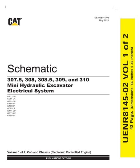 Schematic Caterpillar 307.5, 308, 308.5, 309, 310 (Electrical System) | UENR8145-02
9,99 $
ADD TO CART
Schematic Caterpillar 307.5, 308, 308.5, 309, 310 (Electrical System) | UENR8145-02
9,99 $
ADD TO CART -
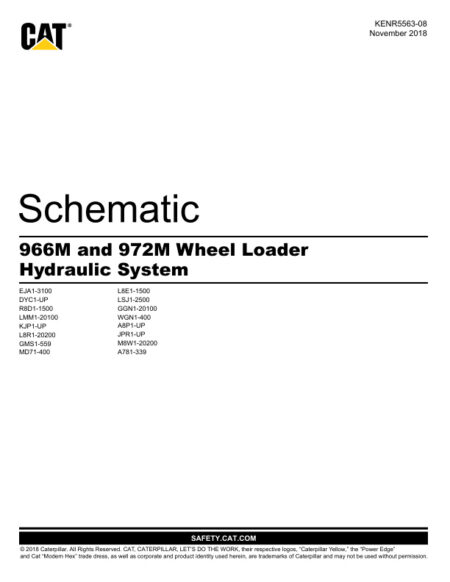 Schematic Caterpillar 966M and 972M Wheel Loader Hydraulic System | KENR5563-08
4,99 $
ADD TO CART
Schematic Caterpillar 966M and 972M Wheel Loader Hydraulic System | KENR5563-08
4,99 $
ADD TO CART -
 Schematic Caterpillar 906K, 907K AND 908K 906M, 907M AND 908M Compact Wheel Loader Hydraulic System | UENR5406-02
4,99 $
ADD TO CART
Schematic Caterpillar 906K, 907K AND 908K 906M, 907M AND 908M Compact Wheel Loader Hydraulic System | UENR5406-02
4,99 $
ADD TO CART -
 Service manual Caterpillar 352F Excavators with C13 Engine | NDC00001-UP
29,99 $
ADD TO CART
Service manual Caterpillar 352F Excavators with C13 Engine | NDC00001-UP
29,99 $
ADD TO CART -
 Service manual Caterpillar 416E Backhoe Loader Single Tilt Center Pivot with 3054C Engine | MFG00001-UP
29,99 $
ADD TO CART
Service manual Caterpillar 416E Backhoe Loader Single Tilt Center Pivot with 3054C Engine | MFG00001-UP
29,99 $
ADD TO CART
Reviews
There are no reviews yet.