3114, 3116 and 3126 MUI Engine Governors
– Dashpot (Types I, III, IV, V, VI, and VII)
– Dual Horsepower (Type VI)
– Dual Horsepower (Type VII)
– Fuel Ratio Control (Types I and IV)
– Fuel Ratio Control (Types V, VI, and VII)
– Fuel Shutoff Solenoid
– Fuel Transfer Pump
– Governor (Type I)
– Governor (Type I) – Assemble
– Governor (Type I) – Disassemble
– Governor (Type II)
– Governor (Type II) – Assemble
– Governor (Type II) – Disassemble
– Governor (Type III)
– Governor (Type III) – Assemble
– Governor (Type III) – Check
– Governor (Type III) – Disassemble
– Governor (Type IV)
– Governor (Type IV) – Assemble
– Governor (Type IV) – Disassemble
– Governor (Type V)
– Governor (Type V) – Adjust
– Governor (Type V) – Assemble
– Governor (Type V) – Disassemble
– Governor (Type VI)
– Governor (Type VI) – Adjust
– Governor (Type VI) – Assemble
– Governor (Type VI) – Check
– Governor (Type VI) – Disassemble
– Governor (Type VII)
– Governor (Type VII) – Adjust
– Governor (Type VII) – Assemble
– Governor (Type VII) – Check
– Governor (Type VII) – Disassemble
– Governor (Types I, II, and Some III) – Adjust
– Governor (Types I, II, IV, and V) – Check
– Governor (Types IV and Some III) – Adjust
– Governor Bias Spring (Most Types IV, V, and VI)
– Governor Bumper Spring (Some Type IV)
– Governor Identification – Introduction
– Governor Limiting Circuit (Types I, II, III, and IV)
– Governor Limiting Circuit (Types V, VI, and VII)
– Governor Performance Data
– Governor Servo (Types I, III, IV, V, VI, and VII)
– Governor Speed Circuit
– Installation of Governor on 1U7326 Governor Calibration
– Prepare Calibration Bench for Test Procedure
– Setting the Governor Load Stop Dimension for More Than 9.00
– Specification
– Throttle Lever (Types IV, V, VI, VII, and Some III) – Install
– Throttle Lever (Types IV, V, VI, VII, and Some III) – Remove
– Throttle Lever Orientation (Types IV, V, VI, VII, and Some III)
– Torque Limiter Device (Some Type V)
37-MT, 41-MT, and 42-MT Series Starting Motors
– Brush and Brush Holder – Check
– Component Description
– Engine Does Not Crank with Starting Motor On and Pinion
– General Information
– General Information
– General Information
– No Load – Test
– Normal Operation
– Pinion Clearance – Adjust
– Service Tools
– Starting Motor
– Starting Motor – Assemble – 37-MT and 41-MT
– Starting Motor – Assemble – 42-MT
– Starting Motor – Disassemble – 37-MT and 41-MT
– Starting Motor – Disassemble – 42-MT
– Starting Motor Does Not Turn or Turns Slowly
– Starting Motor Solenoid – Test
Air Conditioning and Heating R134a for All Caterpillar Machines
– Refrigerant Compressor
– System Capacities for Refrigerant (Off-Highway Trucks)
– General Information
– Identifying the Refrigerant
– Identifying the Air Conditioning System
– Identifying the Heating System
– Refrigerant Expansion Valve System
– Refrigerant Orifice Tube System
– Refrigerant Compressor
– Refrigerant Condenser
– Refrigerant Receiver-Dryer
– Refrigerant Compressor
– Refrigerant Expansion Valve
– In-line Refrigerant Dryer
– Refrigerant Orifice Tube Assembly
– Evaporator Coil
– Refrigerant Accumulator
– Refrigerant Compressor Protection System
– Temperature Control
– Pressure Switch (Refrigerant)
– Cab Pressurization and Filtration System
– Condensate Drainage System
– Refrigerant Compressor
– Service Intervals
– Glossary of Terms
– Required Tools
– Machine Preparation for Troubleshooting
– General Troubleshooting Information
– General Troubleshooting Information
– Visual Inspection (Troubleshooting)
– Air Conditioning System Troubleshooting
– Heating System Troubleshooting
– Automatic Temperature Control System (ECM Controlled)
– Refrigerant Compressor
– Troubleshooting Heating and Air Conditioning Control System
– Troubleshooting Heating and Air Conditioning Control System
– Automatic Temperature Control Panel Troubleshooting – 584
– Troubleshooting Condensate Drainage System
– Machine Preparation for Testing and Adjusting
– Air Conditioning Performance – Test
– Refrigerant Leakage – Test
– Manifold Gauge Set (Refrigerant) – Install
– Refrigerant Recovery
– Refrigerant System – Flush
– Refrigerant Compressor
– Refrigerant Oil – Test
– Refrigerant Compressor – Test
– Refrigerant System – Evacuate
– Refrigerant System – Charge
– Manifold Gauge Set (Refrigerant) – Remove
– Compressor Protection System – Test
– Electronic Heat Control – Test
– Heater Performance – Test
– Heating and Air Conditioning Service Publications
– General Information
– Refrigerant Compressor
– Machine Preparation for Disassembly and Assembly
– Air Conditioner Lines – Remove and Install
– Refrigerant Compressor – Remove and Install
– Refrigerant Accumulator – Remove and Install
– Refrigerant Expansion Valve – Remove and Install
– Refrigerant Receiver-Dryer – Remove and Install
– In-Line Refrigerant Dryer – Remove and Install
– Refrigerant Orifice Tube Assembly – Remove and Install
– Refrigerant Compressor
– System Capacities for Refrigerant (Motor Graders)
– System Capacities for Refrigerant (Off-Highway Trucks) –
– Refrigerant Compressor
Alternator – Delco 21SI
– Alternator
– Alternator – Assemble
– Alternator – Disassemble
– Brush Length – Check
– Capacitor – Test
– Charging System
– Component Description
– Diode Assembly – Test
– Field Winding – Test
– General Information
– General Information
– Insulated Screw – Check
– Normal Operation
– Rectifier – Test
– Regulator – Test
– Residual Magnetism – Restore
– Service Tools
– Stator – Test
Alternator – Delco 27SI
– Alternator
– Alternator
– Alternator – Assemble
– Alternator – Disassemble
– Brush Length – Check
– Capacitor – Test
– Charging System
– Component Description
– Diode Assembly – Test
– Field Winding – Test
– General Information
– General Information
– Insulated Screw – Check
– Normal Operation
– Rectifier – Test
– Regulator – Test
– Residual Magnetism – Restore
– Service Tools
– Stator – Test
Caterpillar Advanced Ride Management (CARM) Seat Suspension System
– Component Descriptions
– General Information
– Troubleshooting
Comfort Series Seat For Caterpillar Machines
– Air Suspension with Air Valve Knob Height Adjustment –
– Air Suspension With Air Valve Knob Height Adjustment –
– Air Suspension With System Air – Assemble
– Air Suspension With System Air – Disassemble
– Air Suspension With Toggle Switch Height Adjustment –
– Air Suspension With Toggle Switch Height Adjustment –
– Comfort Seat Air Suspension with Air Compressor
– Comfort Seat Air Suspension with Air Compressor –
– Comfort Seat Air Suspension with Air Compressor – Assemble
– Comfort Seat Air Suspension with System Air
– Comfort Seat Controls
– Comfort Seat with Front Controls – Assemble
– Comfort Seat with Front Controls – Disassemble
– Comfort Seat with Lumbar Option and Side Controls –
– Comfort Seat with Lumbar Option and Side Controls –
– Comfort Seat with Lumbar, Side Controls, and Slide Swivel
– Component Descriptions
– General Information
– Mechanical Suspension With Fixed Damper – Assemble
– Mechanical Suspension With Fixed Damper – Disassemble
– Mechanical Suspension With Variable Damper – Assemble
– Mechanical Suspension With Variable Damper – Disassemble
– Optimized Seat Air Suspension with Air Compressor
– Optimized Seat Controls
– Optimized Seat with Front Controls – Disassemble and
– Optimized Seat with Lumbar, Side Controls, and Slide Swivel
– Seat Maintenance Interval Schedule
– Serial Number Effectivity
– Swivel Seat – Assemble
– Swivel Seat – Disassemble
– Troubleshooting
– Troubleshooting Chart
Contour Series Seat
– Air Suspension with Air Valve Knob Height Adjustment –
– Air Suspension With Air Valve Knob Height Adjustment –
– Air Suspension With System Air – Assemble
– Air Suspension With System Air – Disassemble
– Air Suspension With Toggle Switch Height Adjustment –
– Air Suspension With Toggle Switch Height Adjustment –
– Contour Seat Air Suspension with Air Compressor
– Contour Seat Air Suspension with Air System
– Contour Seat Controls
– Contour Seat With Front Controls – Assemble
– Contour Seat With Front Controls – Disassemble
– Contour Seat With Lumbar Option and Side Controls –
– Contour Seat With Lumbar Option and Side Controls –
– Mechanical Suspension
– Mechanical Suspension With Fixed Damper – Assemble
– Mechanical Suspension With Fixed Damper – Disassemble
– Mechanical Suspension With Variable Damper – Assemble
– Mechanical Suspension With Variable Damper – Disassemble
– Swivel Seat – Assemble
– Swivel Seat – Disassemble
– Troubleshooting Chart
D6M Track-Type Tractor Hydraulic System
– General Information
– Hydraulic Pump – Piston
– Hydraulic Tank and Filter
– Implement Control Valve
– Signal Resolver Network
– Testing and Adjusting
D6M Track-Type Tractor
– Additional Reference Material
– Adjustable Arm Rest
– After Starting Engine
– Aftermarket Oil Additives
– Air Conditioner – Test
– Air Conditioner Belt – Inspect/Adjust/Replace
– Alternator and Fan Belts – Inspect/Adjust/Replace
– AM FM Cassette Radio
– Backup Alarm
– Backup Alarm – Test
– Battery – Inspect
– Battery – Recycle
– Battery Disconnect Switch
– Battery, Battery Cable or Battery Disconnect Switch – Replace
– Before Operation
– Before Starting Engine
– Brake Pedal Position
– Brakes, Indicators and Gauges – Test
– Braking System – Test
– Bulldozer Blade Lift Control
– Bulldozer Blade Tilt
– Bulldozer Blade Tilt and Angle Control
– Bulldozer Blade Tip
– Bulldozer Power Angling Tilt Hinge Pins – Lubricate
– Bulldozing
– Burn Prevention
– Cab Air Filter – Clean/Replace
– Cab Door
– Caterpillar Monitoring System
– Caterpillar Reference Material
– Changing Direction and Speed
– Characteristics of Diesel Fuel
– Circuit Breakers – Reset
– Conventional Coolant/Antifreeze Cooling System Maintenance
– Coolant Recommendations
– Cooling System Coolant (DEAC) – Change
– Cooling System Extended Life Coolant – Change
– Cooling System Extended Life Coolant Extender – Add
– Cooling System Level – Check
– Cooling System Water Temperature Regulator – Clean/Replace
– Crushing Prevention and Cutting Prevention
– Cutting Edges and End Bits
– Cutting Edges and End Bits – Inspect/Replace
– Decommissioning and Disposal
– Diesel Engine Antifreeze/Coolant – DEAC
– Diesel Fuel Recommendations
– Engine Air Filter Primary Element – Clean/Replace
– Engine Air Filter Secondary Element – Replace
– Engine Air Precleaner – Clean
– Engine Crankcase Breather – Clean
– Engine Oil – Cat Machine Diesel Engines
– Engine Oil and Filter – Change
– Engine Oil Level – Check
– Engine Start Switch
– Engine Starting
– Engine Starting with Jump Start Cables
– Engine Valve Lash and Fuel Injector Timing – Check
– English (SAE) Fasteners
– Equalizer Bar Center Pin – Lubricate
– Equalizer Bar Pins – Inspect
– Equalizer Bar Pins – Lubricate
– Equipment Lowering with Engine Stopped
– Equipment Lowering with Engine Stopped
– Ether Starting Aid
– Ether Starting Aid Cylinder – Replace
– Extended Life Coolant
– Extended Life Coolant Cooling System Maintenance
– Final Drive Oil – Change
– Final Drive Oil Level – Check
– Fire Prevention and Explosion Prevention
– Foreword
– Fuel Information for Diesel Engines
– Fuel System – Prime
– Fuel System Primary Filter – Clean/Replace
– Fuel System Primary Filter/Water Separator – Drain
– Fuel System Secondary Filter – Replace
– Fuel Tank Cap and Strainer – Clean
– Fuel Tank Water and Sediment – Drain
– Fuses – Replace
– Gauges
– General Coolant Information
– General Fuel Information
– General Hazard Information
– General Information
– Governor and Decelerator
– Heating and Air Conditioning Controls
– Horn
– Hose Clamps
– Hydraulic Oil
– Hydraulic System Case Drain Filter – Replace
– Hydraulic System Oil – Change
– Hydraulic System Oil Filter – Replace
– Hydraulic System Oil Level – Check
– Land Clearing
– Leaving the Machine
– Lifting and Tying Down the Machine
– Light Switches
– Lubricant Information
– Lubricant Viscosities
– Lubricating Grease
– Machine Operation
– Machine Operation Information
– Machine Parking
– Maintenance Interval Schedule
– Metric (ISO) Fasteners
– Mirror
– Model View Illustrations
– Mounting and Dismounting
– Mounting and Dismounting
– Normal Steering
– Oil Filter – Inspect
– Parking Brake Control
– Pivot Shaft Oil Level – Check
– Prestart Checks
– Product Identification Number, Serial Number and EU’s CE
– Radiator Core – Clean
– Radiator Pressure Cap – Clean/Replace
– Re-refined Base Stock Oils
– Recoil Spring Compartment Oil Level – Check
– Refill Capacities
– Ripper Control
– Ripper Linkage and Cylinder Bearings – Lubricate
– Ripper Tip and Shank Protector
– Ripper Tip and Shank Protector – Inspect/Replace
– Ripping
– Rollover Protective Structure (ROPS) – Inspect
– Sampling Interval and Location of Sampling Valve
– Seat Adjustment
– Seat and Seat Belt Checks
– Seat Belt
– Seat Belt – Inspect
– Seat Belt Adjustment
– Service Brake Control
– Shipping the Machine
– Sound Information and Vibration Information
– Specialty Lubricants
– Standard Torque for Worm Drive Band Hose Clamps
– Starting Above 0°C (32°F)
– Starting Below 0°C (32°F)
– Starting with Auxiliary Start Receptacle
– Steering Clutch and Brake Control
– Steering on a Steep Downgrade
– Stopping the Engine
– Stopping the Machine
– Supplemental Coolant Additive
– Synthetic Basestock Oils
– S·O·S Analysis
– S·O·S Coolant Analysis
– Torques for Ground Engaging Tool Bolts
– Towing the Machine
– Track Adjustment – Adjust
– Track Adjustment – Check
– Track Pins – Inspect
– Track Roller Frame – Inspect
– Track Roller Frame Guides – Inspect
– Tracks
– Transmission Control
– Transmission Magnetic Screen – Clean
– Transmission Oil – Change
– Transmission Oil Filter – Replace
– Transmission Oil Level – Check
– Transmission/Drive Train Oil
– Walk-Around Inspection
– Walk-Around Inspection
– Warning Signs and Labels
– Warranty Information
– Windows
– Windows – Clean
– Windshield Washer Reservoir – Fill
– Windshield Wiper and Washer Control
– Windshield Wipers – Inspect/Replace
Disassembly and Assembly D6M Track-Type Tractor Engine Supplement
– Air Cleaner – Remove and Install
– Alternator – Remove and Install
– Bottom Guard – Remove and Install
– Electric Starting Motor – Remove and Install
– Engine and Torque Converter – Connect
– Engine and Torque Converter – Install
– Engine and Torque Converter – Remove
– Engine and Torque Converter – Separate
– Engine Oil Cooler – Remove and Install
– Engine Oil Filter and Base – Install
– Engine Oil Filter and Base – Remove
– Engine Side Guards – Remove and Install
– Fan and Fan Drive – Install
– Fan and Fan Drive – Remove
– Fan Drive – Assemble
– Fan Drive – Disassemble
– Fuel Filter and Base – Remove and Install
– Fuel Priming Pump – Remove and Install
– Governor Control Linkage and Decelerator – Assemble
– Governor Control Linkage and Decelerator – Disassemble
– Governor Control Linkage and Decelerator – Install
– Governor Control Linkage and Decelerator – Remove
– Hood – Remove and Install
– Muffler – Remove and Install
– Radiator – Assemble
– Radiator – Disassemble
– Radiator – Install
– Radiator – Remove
– Turbocharger – Remove and Install
– Water Pump – Assemble
– Water Pump – Disassemble
– Water Pump – Install
– Water Pump – Remove
– Water Temperature Regulator – Remove and Install
Disassembly and Assembly D6M Track-Type Tractor Machine Systems
– Air Conditioner and Heater Fan Motor – Remove and Install
– Air Conditioner Dryer – Remove and Install
– Battery – Remove and Install
– Bulldozer – Install
– Bulldozer – Remove
– Bulldozer Angle Cylinder – Install
– Bulldozer Angle Cylinder – Remove
– Bulldozer C-Frame – Install
– Bulldozer C-Frame – Remove
– Bulldozer Control Valve – Assemble
– Bulldozer Control Valve – Disassemble
– Bulldozer Control Valve – Install
– Bulldozer Control Valve – Remove
– Bulldozer Lift Cylinder – Install
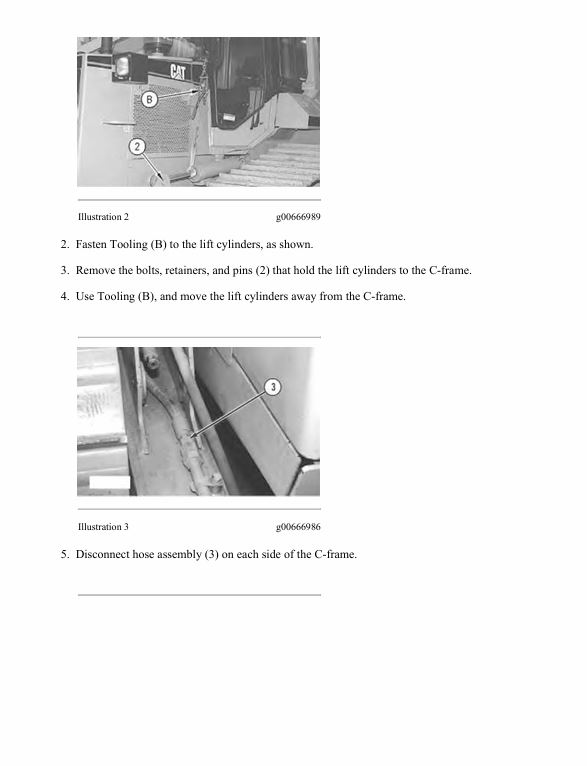
– Bulldozer Lift Cylinder – Remove
– Bulldozer Lift Cylinder Mounts – Remove and Install
– Bulldozer Tilt Cylinder – Install
– Bulldozer Tilt Cylinder – Remove
– Cab – Install
– Cab – Remove
– Equipment Pump – Assemble
– Equipment Pump – Disassemble
– Equipment Pump – Install
– Equipment Pump – Remove
– Governor Control Linkage and Decelerator – Assemble
– Governor Control Linkage and Decelerator – Disassemble
– Governor Control Linkage and Decelerator – Install
– Governor Control Linkage and Decelerator – Remove
– Hydraulic Tank – Remove and Install
– Refrigerant Evaporator Core and Heater Core – Remove and
– Rollover Protective Structure (ROPS) – Remove and Install
Disassembly and Assembly D6M Track-Type Tractor Power Train
– Axle Shaft – Remove and Install
– Bevel and Transfer Gears – Assemble
– Bevel and Transfer Gears – Disassemble
– Control Valve (Transmission Flywheel Clutch) – Assemble
– Control Valve (Transmission Flywheel Clutch) – Disassemble
– Duo-Cone Conventional Seals – Install
– Duo-Cone Inverted Seals – Install
– Equalizer Bar – Assemble
– Equalizer Bar – Disassemble
– Equalizer Bar – Install
– Equalizer Bar – Remove
– Final Drive – Assemble
– Final Drive – Disassemble
– Final Drive – Install
– Final Drive – Remove
– Final Drive Planetary Carrier (In Chassis) – Remove and Install
– Final Drive, Steering Clutch, and Brakes – Connect
– Final Drive, Steering Clutch, and Brakes – Separate
– Flywheel Clutch Control Valve – Install
– Flywheel Clutch Control Valve – Remove
– Front Track Roller Frame – Install
– Front Track Roller Frame – Remove
– Idler – Assemble
– Idler – Disassemble
– Idler – Install
– Idler – Remove
– Main Drive Shaft – Remove and Install
– Oil Filter and Base (Power Train) – Assemble
– Oil Filter and Base (Power Train) – Disassemble
– Oil Filter and Base (Power Train) – Install
– Oil Filter and Base (Power Train) – Remove
– Pivot Shaft – Remove and Install
– Power Train Oil Pump – Assemble
– Power Train Oil Pump – Disassemble
– Power Train Oil Pump – Install
– Power Train Oil Pump – Remove
– Priority Valve – Remove and Install
– Pump Drive – Assemble
– Pump Drive – Disassemble
– Pump Drive – Install
– Pump Drive – Remove
– Recoil Spring – Install
– Recoil Spring – Remove
– Sprocket Segment – Remove and Install
– Steering Clutch and Brake – Assemble
– Steering Clutch and Brake – Disassemble
– Steering Clutch and Brake – Install
– Steering Clutch and Brake – Remove
– Steering Clutch and Brake Control Valve – Assemble
– Steering Clutch and Brake Control Valve – Disassemble
– Steering Clutch and Brake Control Valve – Install
– Steering Clutch and Brake Control Valve – Remove
– Torque Converter – Assemble
– Torque Converter – Disassemble
– Torque Converter – Install
– Torque Converter – Remove
– Torque Converter Outlet Relief Valve – Assemble
– Torque Converter Outlet Relief Valve – Disassemble
– Torque Converter Outlet Relief Valve – Install
– Torque Converter Outlet Relief Valve – Remove
– Track – Assemble
– Track – Connect
– Track – Disassemble
– Track – Separate
– Track Adjuster – Remove and Install
– Track Roller – Assemble
– Track Roller – Disassemble
– Track Roller – Install
– Track Roller – Remove
– Track Roller Frame – Install
– Track Roller Frame – Remove
– Transmission – Assemble
– Transmission – Disassemble
– Transmission and Bevel Gears – Connect
– Transmission and Bevel Gears – Install
– Transmission and Bevel Gears – Remove
– Transmission and Bevel Gears – Separate
– Transmission Brake – Assemble
– Transmission Brake – Disassemble
– Transmission Brake – Install
– Transmission Brake – Remove
– Transmission Flywheel Clutch – Assemble
– Transmission Flywheel Clutch – Disassemble
– Transmission Flywheel Clutch – Install
– Transmission Hydraulic Control Valve – Assemble
– Transmission Hydraulic Control Valve – Disassemble
– Transmission Hydraulic Control Valve – Install
– Transmission Hydraulic Control Valve – Remove
Flexxaire Fan
– Calibration
– Control System
– Control System
– Control System – Remove and Install
– Hydraulic Actuated Fan – Assemble
– Hydraulic Actuated Fan – Disassemble
– Hydraulic Actuated Fan System
– Mechanical Actuated Fan
– Mechanical Actuated Fan – Assemble
– Mechanical Actuated Fan – Disassemble
– Mechanical Actuated Fan System
– Setup
– Torque Specifications (Flexxaire Fan)
MSS3s Machine Security System
– Cat Data Link – Test
– Connector Contact Description
– Connector Locations
– Data Links
– Determining Diagnostic Trouble Codes
– Diagnostic Capabilities
– Diagnostic Operation
– Diagnostic Trouble Codes
– ECM – Configure
– ECM – Replace
– ECM Output Driver – Test
– ECM Software – Install
– Electrical Connector – Inspect
– Electrical Power Supply – Test
– Electronic Control Module (ECM)
– Emerging Symptom Information
– Engine Does Not Crank and Status Indicator Is Green
– Engine Does Not Start and Status Indicator Is Continuously
– Events
– Factory Password – Obtain
– General Information
– General Information
– General Information
– Glossary of Terms
– Key – Program
– Key Information
– Lost Key (MSS)
– Machine Preparation for Troubleshooting
– Normal Operation
– Operation of Status Indicator
– Product Identification Number – Program
– Protected Functions
– Scheduled Access – “Security System Bypass Times”
– Service Operation Using Machine Security System
– Service Operation Using Service Tool
– Service Tools
– Software – Uninstall – “Immobilizer” Feature
– Symptom Troubleshooting
– System Components
– System Disarm – Program – Security System Bypass
– System Overview
– System Schematic
– Time – Set
– Visual Inspection
– Wiring Harness (Open Circuit) – Test
– Wiring Harness (Short Circuit) – Test
Machine Security System
– Cat Data Link
– Diagnostic Code List
– Diagnostic Operation
– Electrical Component and Connector Locations
– Electrical Connector – Inspect
– Electronic Control Module (ECM)
– Electronic Control Module (ECM) – Flash Program
– Electronic Control Module (ECM) – Replace
– Emerging Symptom Information
– Engine Does Not Crank and Status Indicator Is Green
– Engine Does Not Start and Status Indicator Is Continuously
– Events
– Factory Password – Obtain
– General Information
– General Information
– General Information
– Glossary of Terms
– Key – Program
– Key Information
– Lost Key
– MID 124 – CID 0168 – FMI 00
– MID 124 – CID 0168 – FMI 01
– MID 124 – CID 0248 – FMI 12
– MID 124 – CID 0817 – FMI 04
– MID 124 – CID 1391 – FMI 03
– MID 124 – CID 1391 – FMI 04
– MID 124 – CID 1392 – FMI 03
– MID 124 – CID 1392 – FMI 04
– Normal Operation
– Operation of Status Indicator
– Product Identification Number – Program
– Protected Functions
– Scheduled Access – “Security System Bypass Times”
– Service Operation Using Machine Security System
– Service Operation Using Service Tool
– Service Tools
– Software – Uninstall – “Immobilizer” Feature
– Symptom Troubleshooting
– System Components
– System Disarm – Program – Security System Bypass
– System Overview
– System Schematic
– Time – Set
– Using Caterpillar Electronic Technician to Determine
SUPPLEMENT FOR – 3114, 3116 AND 3126 ENGINES FOR CATERPILLAR
– Aftercooler Group
– Air Cleaner Group
– Air Lines Group
– Alternator Mounting Group
– Alternators And Regulators
– Blower Fan Group
– Coolant Temperature Switch
– Exhaust Extension Group
– Fan Drive
– Flexible Coupling Group
– Fuel Pressure Switch
– Introduction
– Muffler Group
– Oil Pan Group
– Oil Pressure Switch
– Primary Fuel Filter
– Pump Drive Group
– Service Meter
– Speed Sensor (Magnetic)
– Starting Motor
– Systems Operation
– Testing and Adjusting
– Torque Converter Group
– Transmission Oil Temperature Switch
– Water Temperature Regulator
Schematic Caterpillar D6M Track-Type Tractor Hydraulic System
Schematic Caterpillar D6M Tractor Electrical Schematic
Specifications D6M Track-Type Tractor Hydraulic System
– Bulldozer Angle Control
– Bulldozer Angle Control Valve
– Bulldozer Angle Cylinder
– Bulldozer Blade
– Bulldozer Lift and Tilt Control Linkage
– Bulldozer Lift Control Valve
– Bulldozer Lift Cylinder
– Bulldozer Tilt Control Valve
– Bulldozer Tilt Cylinder
– Cutting Edges and End Bits
– Equipment Control Valves
– Hydraulic Pump
– Hydraulic Tank and Filter
– Inlet Manifold
– Pressure and Flow Compensator Valve
– Relief Valve For Head and Rod Ends Of Bulldozer Angle
– Relief Valve For Rod Ends Of Bulldozer Lift Cylinders
– Ripper Control
– Ripper Control Valve
– Ripper Lift Cylinder
– Ripper Mounting
Specifications D6M Track-Type Tractor Power Train
– Bevel and Transfer Gears – Power Shift
– Cab Mounting
– Drawbar
– Drive Shaft – Power Shift
– Equalizer Bar
– Fender
– Final Drive
– Front Frame
– Idlers (Track)
– Pivot Bar
– Platform
– Priority Valve
– Recoil Group
– Relief Valve (Torque Converter Outlet)
– Rollover Protective Structure (ROPS)
– Steering and Brake Control Valve
– Steering Clutch and Brake and Foot Brake Controls Linkage
– Steering Clutches and Brakes
– Torque Converter
– Torque Converter and Pump Drive Housing
– Track Carrier Rollers
– Track Roller Frames
– Track Rollers – Single Flange and Double Flange
– Tracks
– Transmission – Power Shift
– Transmission and Torque Converter Pump
– Transmission Controls and Parking Brake Linkage
– Transmission Hydraulic Control – Power Shift
– Transmission Oil Filter
– Transmission Selector and Pressure Control Valve – Power
Systems Operation D6M Track-Type Tractor Power Train
– Bevel and Transfer Gears
– Equalizer Bar
– Final Drive
– General Information
– Magnetic Screen
– Pivot Shaft
– Power Train Hydraulic System
– Priority Valve
– Selector and Pressure Control Valve
– Steering Clutch and Brake
– Torque Converter
– Torque Converter Hydraulic System
– Torque Converter Operation
– Track Idler
– Track Roller
– Track Roller Frame
– Transmission
– Transmission Hydraulic Control
– Undercarriage
Systems Operation EquipmentManager Dealer Administrator Manual
– Active Fleet
– Administration
– Asset Watch
– Enable Program
– Equipment Usage
– Fault Codes
– Fuel Results
– General Information
– Getting Started
– Health Watch
– Maintenance Watch
– Major Repair
– Manage Equipment Groups
– Manage Event Tracking
– Manage Hardware
– Manage Major Repair Tracking
– Manage Planned Maintenance
– Manage Time Fence and Geographic Fence
– Manage Users
– Operation and Maintenance Manual
– Planned Maintenance
– Preference Detail
– Preferences
– Product Link Installation
– Product Monitoring
– Product Usage
– Reports
– Setup Subscriptions
– Time Fence and Geographic Fence
– Upload Data
– Verify Machine Records and Ownership
Systems Operation EquipmentManager User Guide
– Getting Started
– Manage Major Repair Tracking
– Manage Time Fence and Geographic Fence
– Manage Planned Maintenance
– Preferences
– Preference Detail
– Asset Watch
– Time Fence and Geographic Fence
– Maintenance Watch
– Planned Maintenance
– Major Repair
– Verify Machine Records and Ownership
– Health Watch
– Fuel Results
– Fault Codes
– Reports
– Product Usage
– Product Monitoring
– Operation and Maintenance Manual
– Equipment Usage
– Manage Users
– Product Link Installation
– Administration
– Manage Equipment Groups
– Manage Hardware
– Manage Event Tracking
– Upload Data
– General Information
Systems Operation Troubleshooting Testing and Adjusting Product Link – PL522 523
– System Components
– Reports and Messages Not Available
– Position Reports Not Available
– Reporting Interval Erratic
– Diagnostics and Events Not Available
– Operating Hours Discrepancy
– Event Code List
– Diagnostic Code List
– MID 161 – CID 0168 – FMI 00
– MID 161 – CID 0168 – FMI 01
– MID 161 – CID 0254 – FMI 04
– Installation Parameters Configure
– MID 161 – CID 0254 – FMI 12
– MID 161 – CID 1250 – FMI 09
– MID 161 – CID 1251 – FMI 03
– MID 161 – CID 1888 – FMI 14
– MID 161 – CID 3766- FMI 14
– Electronic Control Module (ECM) – Flash Program
– Electronic Control Module (ECM) – Replace
– Electrical Connector – Inspect
– Wiring Harness (Open Circuit) – Test
– Wiring Harness (Short Circuit) – Test
– Configuration
– Specifications
– System Schematic
– Spare Input Configure
– Commands
– General Information
– Service Tools
– Diagnostic Capabilities
– Electronic Service Tool Does Not Communicate with ECM
– System Overview
Systems Operation Troubleshooting Testing and Adjusting Product Link 121S 300
– System Components
– Service Tools
– Diagnostic Capabilities
– Electronic Service Tool Does Not Communicate with ECM
– ECM Does Not Communicate with User Interface
– Position Reports Not Available
– Reporting Interval Erratic
– Diagnostics and Events Not Available
– Operating Hours Discrepancy
– Event Code List
– Diagnostic Code List
– Spare Inputs
– MID 122 – CID 0168 – FMI 00
– MID 122 – CID 0168 – FMI 01
– MID 122 – CID 0254 – FMI 04
– MID 122 – CID 0254 – FMI 12
– MID 122 – CID 0269 – FMI 03
– MID 122 – CID 0269 – FMI 04
– MID 122 – CID 1250 – FMI 09
– MID 122 – CID 1251 – FMI 03
– Electronic Control Module (ECM) – Flash Program
– Electronic Control Module (ECM) – Replace
– Configuration
– Electrical Connector – Inspect
– Wiring Harness (Open Circuit) – Test
– Wiring Harness (Short Circuit) – Test
– Specifications
– System Schematic
– Installation Parameters Configure
– Report Parameters Configure
– Wireless Service Configure
– Spare Input Configure
– Commands
– General Information
– System Overview
Testing and Adjusting D6M Track-Type Tractor Power Train
– Testing and Adjusting
– Troubleshooting
Service manual Caterpillar D6M XL & D6M LGP TRACTORS / POWERSHIFT with 3116 ENGINE | 2YS00001-UP
24,99 $
Format: PDF
Type: Service Manual
Pages: 5378
Size: 220 Mb
No.: 2YS00001-UP
-
 Service manual Caterpillar 426C Backhoe Loader with 3054 Engine | 1CR00001-UP
24,99 $
ADD TO CART
Service manual Caterpillar 426C Backhoe Loader with 3054 Engine | 1CR00001-UP
24,99 $
ADD TO CART -
 Schematic Caterpillar 325D and 329D Excavator 329D MHPU Hydraulic System | RENR7386-06
4,99 $
ADD TO CART
Schematic Caterpillar 325D and 329D Excavator 329D MHPU Hydraulic System | RENR7386-06
4,99 $
ADD TO CART -
 Service manual Caterpillar 450E Backhoe Loader with C4.4 Engine | RBA00001-UP
24,99 $
ADD TO CART
Service manual Caterpillar 450E Backhoe Loader with C4.4 Engine | RBA00001-UP
24,99 $
ADD TO CART -
 Service manual Caterpillar 320 Excavator with C7.1 Engine | XAR00001-UP
24,99 $
ADD TO CART
Service manual Caterpillar 320 Excavator with C7.1 Engine | XAR00001-UP
24,99 $
ADD TO CART -
 Schematic Caterpillar 972M Steel Mill Wheel Loader Electrical System | UENR8356-02
9,99 $
ADD TO CART
Schematic Caterpillar 972M Steel Mill Wheel Loader Electrical System | UENR8356-02
9,99 $
ADD TO CART -
 Service manual Caterpillar 320E, 320E L & 320E LN Excavators with C6.6 Engine | SHX00001-UP
24,99 $
ADD TO CART
Service manual Caterpillar 320E, 320E L & 320E LN Excavators with C6.6 Engine | SHX00001-UP
24,99 $
ADD TO CART
Reviews
There are no reviews yet.