Hitachi ZX225USLC-7 Hydraulic Excavator WDF150-EN-00 (2022.08.05) (Preview)
WDF150-EN-00
– INTRODUCTION
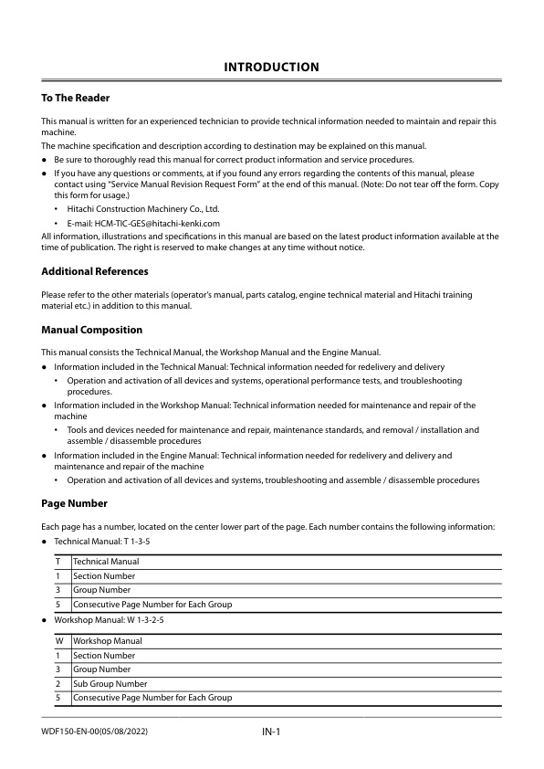
— To The Reader
— Additional References
— Manual Composition
— Page Number
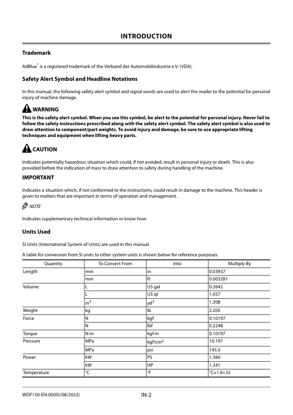
— Trademark
— Safety Alert Symbol and Headline Notations
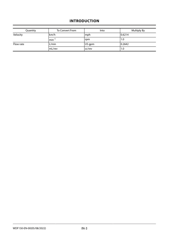
— Units Used
– SYMBOL AND ABBREVIATION
— Symbol and Abbreviation
– CONTRASTING LIST OF PART NAME
— Contrasting List of Part Name between Technical Manual and Parts Catalog
– SAFETY
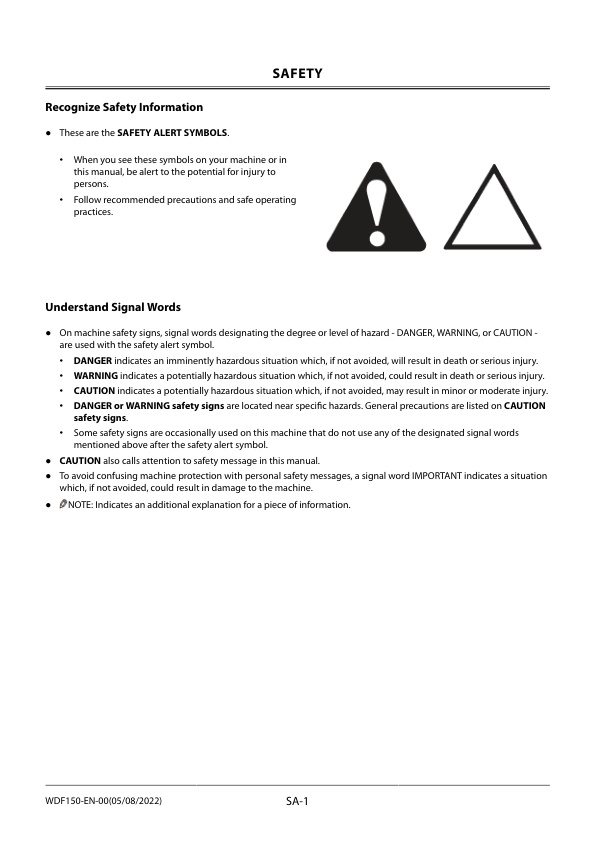
— Recognize Safety Information
— Understand Signal Words
— Follow Safety Instructions
— Prepare for Emergencies
— Wear Protective Clothing
— Protect Against Noise
— Inspect Machine
— General Precautions for the Cab
— Use Handrail and Steps
— Adjust the Operator’s Seat
— Ensure Safety Before Rising from or Leaving Operator’s Seat
— Fasten Your Seat Belt
— Move and Operate Machine Safely
— Start the Engine Only from Operator’s Seat
— Jump Starting
— Keep Riders off Machine
— Precautions for Operations
— Perform Job Site Risk Assessment Beforehand
— Install OPG Guard
— Restriction of Attachment Installation
— Provide Signals for Jobs Involving Multiple Machines
— Confirm Direction of Machine Travel
— Drive Machine Safely
— Avoid Injury from Rollaway Accidents
— Avoid Accidents from Reversing and Swing Operation
— Keep People Clear from Working Area
— Never Position the Bucket Over Anyone
— Avoid Undercutting
— Avoid Tipping
— Never Undercut a High Bank
— Dig with Caution
— Caution with an Overhead Obstacle
— Avoid Power Lines
— Precautions for Lightning
— Object Handling
— Protect Against Flying Debris and Falling Object
— Park Machine Safely
— Handle Fluids Safely−Avoid Fires
— Transport Safely
— Practice Maintenance Safely
— Warn Others of Service Work
— Support Machine Properly
— Stay Clear of Moving Parts
— Prevent Parts from Flying
— Avoid Injury from Attachment Falling Accident
— Prevent Burns
— Replace Rubber Hoses Periodically
— Avoid High-Pressure Fluids
— Prevent Fires
— Check for Oil Leaks:
— Check for Short circuits:
— Clean up Flammable Materials:
— Check Key Switch:
— Check Heat Shields:
— Evacuating in Case of Fire
— Beware of Exhaust Fumes
— Precautions for Welding and Grinding
— Avoid Heating Near Pressurized Fluid Lines
— Avoid Applying Heat to Lines Containing Flammable Fluids
— Precautions for Handling Accumulator and Gas Damper
— Remove Paint Before Welding or Heating
— Beware of Asbestos and Silica Dust and Other Contamination
— Prevent Battery Explosions
— Service Air Conditioning System Safely
— Handle Chemical Products Safely
— Dispose of Waste Properly
— Never Ride Attachment
— Notes on Aftertreatment Device
— Precautions for Communication Terminal
— Precautions for Communication Terminal Equipment
— Notes on Protection by Operator’s Station when the Machine Rolls Over
— Before Returning the Machine to the Customer
– SECTION AND GROUP CONTENTS
– CONTENTS
– GENERAL
— Precautions for Disassembling and Assembling
— Precautions for Disassembling and Assembling
— Precautions for Using Floating Seal
— Precautions for Using Nylon Sling
— Maintenance Standard Terminology
— Tightening
— Tightening Bolts and Nuts
— Bolt Types
— Specified Tightening Torque Chart
— Tightening Order
— Precautions for Spilt Flange
— Nut and Bolt Locking
— Tightening Piping Joint
— Union Joint
— Pipe Joint
— O-Ring Face Seal Joint
— Quick Coupling
— Screw-In Connection
— Seal Tape Application
— Low-Pressure-Hose Clamp Tightening
— Connecting Hose
— Painting
— Painting
— Bleeding Air
— Bleeding Air from Hydraulic System
— Bleeding Air from Pump
— Bleeding Air from Travel Motor, Swing Motor
— Bleeding Air from Hydraulic Circuit
— Bleeding Air from Fuel System
— Air Bleeding from the Diesel Exhaust Fluid Defrosting Piping
— Preparation
— Preparation before Inspection and Maintenance
— Hydraulic Circuit Pressure Release Procedure
— Pressure Release from Hydraulic Oil Tank
— Pressure Release from Expansion Tank
– MAINTENANCE STANDARD
— Upperstructure
— Maintenance Standard for Pump Device
— Maintenance Standard for Swing Motor
— Undercarriage
— Maintenance Standard for Travel Motor
— Maintenance Standard for Sprocket
— Maintenance Standard for Front Idler
— Maintenance Standard for Upper Roller
— Maintenance Standard for Lower Roller
— Maintenance Standard for Track
— Front Attachment
— Maintenance Standard for Pin and Bushing
— Maintenance Standard for Side Cutter (2014503, 2014504)
— Maintenance Standard for Point (4427919)
— Standard Dimensions for Arm and Bucket Connection
— Standard Dimensions for Arm and Boom Connection
– UPPERSTRUCTURE
— Cab
— Removal of Cab Interior Parts
— Removal of Cab Exterior Parts
— Removal of Wiper
— Removal of Cab Body
— Removal of Controller Assembly and Parts Around the Monitor
— Installation of Controller Assembly and Parts Around the Monitor
— Installation of Cab Body
— Installation of Wiper
— Installation of Cab Exterior Parts
— Installation of Cab Interior Parts
— Dimensions of Cab Glass
— Procedure to Remove Cab Glass
— Procedure to Install Cab Glass
— Procedures to Install Upper Door Glass
— Procedures to Install Upper Front Glass
— Counterweight
— Removal of Counterweight
— Installation of Counterweight
— Main Frame
— Removal of Main Frame
— Installation of Main Frame
— Engine
— Preparation before Removal of Engine
— Removal of Covers and Related Parts Around the Engine
— Removal of Wire Harnesses and Hoses Around the Engine
— Removal of Engine Body
— Installation of Engine Body
— Installation of Wire Harnesses and Hoses Around the Engine
— Installation of Related Parts of the Engine
— Work after Installation of Engine and Installation of Covers
— Radiator Assembly
— Removal of Radiator Assembly
— Installation of Radiator Assembly
— Removal of Radiator
— Installation of Radiator
— Removal of Oil Cooler
— Installation of Oil Cooler
— Removal of Intercooler
— Installation of Intercooler
— Hydraulic Oil Tank
— Removal of Hydraulic Oil Tank
— Installation of Hydraulic Oil Tank
— Fuel Tank
— Removal of Fuel Tank
— Installation of Fuel Tank
— Pump Device
— Removal of Pump Device
— Installation of Pump Device
— Removal of Coupling
— Installation of Coupling
— Disassembly of Pump Device
— Assembly of Pump Device
— Disassembly of Regulator
— Assembly of Regulator
— Disassembly of Solenoid Valve
— Assembly of Solenoid Valve
— Structure of Pilot Pump
— Control Valve
— Removal of Control Valve
— Installation of Control Valve
— Disassembly of Housing
— Assembly of Housing
— Disassembly of Spool (A-Side Control Valve)
— Assembly of Spool (A-Side Control Valve)
— Disassembly of Boom Anti-Drift Valve (Check Valve) (j) (A-Side Control Valve)
— Disassembly of Boom Anti-Drift Valve (Selector Valve) (k) (A-Side Control Valve)
— Assembly of Boom Anti-Drift Valve (j, k) (A-Side Control Valve)
— Disassembly of Overload Relief Valve (h, i, ac, ad) (A-Side Control Valve)
— Assembly of Overload Relief Valve (h, i, ac, ad) (A-Side Control Valve)
— Disassembly of Travel (Right) Spool (n) (A-Side Control Valve)
— Assembly of Travel Spool (n) (A-Side Control Valve)
— Disassembly of Bucket Spool (p) (A-Side Control Valve)
— Assemble of Bucket Spool (p) (A-Side Control Valve)
— Disassembly of Arm 2 Spool (q) (A-Side Control Valve)
— Assembly of Arm 2 Spool (q) (A-Side Control Valve)
— Disassembly of Boom 1 Spool (r) (A-Side Control Valve)
— Assembly of Boom 1 Spool (r) (A-Side Control Valve)
— Disassembly of Boom 3 Spool (s) (A-Side Control Valve)
— Assembly of Boom 3 Spool (s) (A-Side Control Valve)
— Disassembly of Swing Spool (t) (A-Side Control Valve)
— Assembly of Swing Spool (t) (A-Side Control Valve)
— Disassembly of Arm Roll-In Meter-Out Open Control Spool (aa) (A-Side Control Valve)
— Assembly of Arm Roll-In Meter-Out Open Control Spool (aa) (A-Side Control Valve)
— Disassembly of Main Relief Valve (m) (A-Side Control Valve)
— Assembly of Main Relief Valve (m) (A-Side Control Valve)
— Disassembly of Bucket Regeneration Cut Valve (g) (A-Side Control Valve)
— Assembly of Bucket Regeneration Cut Valve (g) (A-Side Control Valve)
— Disassembly of Check Valve (d, f) (A-Side Control Valve)
— Assembly of Check Valve (d, f) (A-Side Control Valve)
— Disassembly of Load Check Valve (e) (A-Side Control Valve)
— Assembly of Load Check Valve (e) (A-Side Control Valve)
— Disassembly of Flow Combiner Valve (ae) (A-Side Control Valve)
— Assembly of Flow Combiner Valve (ae) (A-Side Control Valve)
— Disassembly of Pump 1 Bypass Shut-Out Valve (ab) (A-Side Control Valve)
— Assembly of Pump 1 Bypass Shut-Out Valve (ab) (A-Side Control Valve)
— Disassembly of Check Valves (u, w), Load Check Valves (x, y) (A-Side Control Valve)
— Assembly of Check Valves (u, w), Load Check Valves (x, y) (A-Side Control Valve)
— Disassembly of Boom Lower Meter-In Cut Valve (v) (A-Side Control Valve)
— Assembly of Boom Lower Meter-In Cut Valve (v) (A-Side Control Valve)
— Disassembly of Load Check Valve (z) (A-Side Control Valve)
— Assembly of Load Check Valve (z) (A-Side Control Valve)
— Disassembly and Assembly of Plugs (A-Side Control Valve)
— Disassembly of Spool (B-Side Control Valve)
— Assembly of Spool (B-Side Control Valve)
— Disassembly of Arm Regenerative Valve (j) (B-Side Control Valve)
— Assembly of Arm Regenerative Valve (j) (B-Side Control Valve)
— Disassembly of Arm Rod Anti-Drift Valve (Check Valve) (e) (B-Side Control Valve)
— Disassembly of Arm Rod Anti-Drift Valve (Selector Valve) (d) (B-Side Control Valve)
— Assembly of Arm Rod Anti-Drift Valve (d, e) (B-Side Control Valve)
— Disassembly of Overload Relief Valve (f, aa) (B-Side Control Valve)
— Assembly of Overload Relief Valve (f, aa) (B-Side Control Valve)
— Disassembly of Main Relief Valve (ai) (B-Side Control Valve)
— Assembly of Main Relief Valve (ai) (B-Side Control Valve)
— Disassembly of Load Check Valve (Arm Regenerative Circuit) (ac) (B-Side Control Valve)
— Assembly of Load Check Valve (Arm Regenerative Circuit) (ac) (B-Side Control Valve)
— Disassembly of Load Check Valve (Travel (Left) Tandem Circuit) (ag) (B-Side Control Valve)
— Assembly of Load Check Valve (Travel (Left) Tandem Circuit) (ag) (B-Side Control Valve)
— Disassembly of Check Valve (Main Relief Circuit) (ah) (B-Side Control Valve)
— Assembly of Check Valve (Main Relief Circuit) (ah) (B-Side Control Valve)
— Disassembly of Travel (Left) Spool (g) (B-Side Control Valve)
— Assembly of Travel (Left) Spool (g) (B-Side Control Valve)
— Disassembly of Auxiliary 1 Spool (h) (B-Side Control Valve)
— Assembly of Auxiliary 1 Spool (h) (B-Side Control Valve)
— Disassembly of Arm 1 Spool (i) (B-Side Control Valve)
— Assembly of Arm 1 Spool (i) (B-Side Control Valve)
— Disassembly of Boom 2 Spool (k) (B-Side Control Valve)
— Assembly of Boom 2 Spool (k) (B-Side Control Valve)
— Disassembly of Pump 3 Bypass Shut-Out Valve (ae) (B-Side Control Valve)
— Assembly of Pump 3 Bypass Shut-Out Valve (ae) (B-Side Control Valve)
— Disassembly of Auxiliary 2 Spool (m) (B-Side Control Valve)
— Assembly of Auxiliary 2 Spool (m) (B-Side Control Valve)
— Disassembly of Digging Regenerative Valve (ab) (B-Side Control Valve)
— Assembly of Digging Regenerative Valve (ab) (B-Side Control Valve)
— Disassembly of Auxiliary Flow Combiner Valve (z) (B-Side Control Valve)
— Assembly of Auxiliary Flow Combiner Valve (z) (B-Side Control Valve)
— Disassembly of Arm Bottom Anti-Drift Valve (Check Valve) (y) (B-Side Control Valve)
— Disassembly of Arm Bottom Anti-Drift Valve (Selector Valve) (x) (B-Side Control Valve)
— Assembly of Arm Bottom Anti-Drift Valve (x, y) (B-Side Control Valve)
— Disassembly of Check Valve (Auxiliary Flow Combiner Circuit) (af) (B-Side Control Valve)
— Assembly of Check Valve (Auxiliary Flow Combiner Circuit) (af) (B-Side Control Valve)
— Disassembly of Arm 1 Flow Rate Control Valve (Poppet Valve) (s) (B-Side Control Valve)
— Disassembly of Arm 1 Flow Rate Control Valve (Selector Valve) (t) (B-Side Control Valve)
— Assembly of Arm 1 Flow Rate Control Valve (s, t) (B-Side Control Valve)
— Disassembly of Load Check Valve (Boom 2 Parallel Circuit) (u) (B-Side Control Valve)
— Assembly of Load Check Valve (Boom 2 Parallel Circuit) (u) (B-Side Control Valve)
— Disassembly of Load Check Valve (Auxiliary 2 Tandem Circuit) (r) (B-Side Control Valve)
— Assembly of Load Check Valve (Auxiliary 2 Tandem Circuit) (r) (B-Side Control Valve)
— Disassembly of Load Check Valve (Travel (Left) Parallel Circuit) (n) (B-Side Control Valve)
— Assembly of Load Check Valve (Travel Parallel Circuit) (n) (B-Side Control Valve)
— Disassembly of Load Check Valve (Auxiliary 2 Parallel Circuit) (ad) (B-Side Control Valve)
— Assembly of Load Check Valve (Auxiliary 2 Parallel Circuit) (ad) (B-Side Control Valve)
— Disassembly of Load Check Valve (Digging Regenerative Circuit) (w) (B-Side Control Valve)
— Assembly of Load Check Valve (Digging Regenerative Circuit) (w) (B-Side Control Valve)
— Disassembly of Auxiliary Flow Rate Control Valve (Poppet Valve) (p) (B-Side Control Valve)
— Disassembly of Auxiliary Flow Rate Control Valve (Selector Valve) (q) (B-Side Control Valve)
— Assembly of Auxiliary Flow Rate Control Valves (p, q) (B-Side Control Valve)
— Disassembly of Auxiliary 2 Hydraulic Pressure Source Control Spool (ak) (B-Side Control Valve)
— Assembly of Auxiliary 2 Hydraulic Pressure Source Control Spool (ak) (B-Side Control Valve)
— Disassembly and Assembly of Plugs (B-Side Control Valve)
— Removal of Blade Control Valve
— Installation of Blade Control Valve
— Disassembly of Blade Control Valve
— Assembly of Blade Control Valve
— Swing Device
— Removal of Swing Device
— Installation of Swing Device
— Removal of Swing Device (With Blade)
— Installation of Swing Device (With Blade)
— Disassembly of Swing Reduction Gear
— Assembly of Swing Reduction Gear
— Disassembly of Swing Motor
— Assembly of Swing Motor
— Pilot Valve
— Removal of Pilot Valve (Left)
— Installation of Pilot Valve (Left)
— Removal of Pilot Valve (Right)
— Installation of Pilot Valve (Right)
— Disassembly of Pilot Valves (Left and Right)
— Assembly of Pilot Valves (Left and Right)
— Removal of Travel Pilot Valve
— Installation of Travel Pilot Valve
— Disassembly of Travel Pilot Valve
— Assembly of Travel Pilot Valve
— Removal of Blade Pilot Valve
— Installation of Blade Pilot Valve
— Disassembly of Blade Pilot Valve
— Assembly of Blade Pilot Valve
— Solenoid Valve
— Removal of Pilot Shut-Off Solenoid Valve
— Installation of Pilot Shut-Off Solenoid Valve
— Disassembly of Pilot Shut-Off Solenoid Valve
— Assembly of Pilot Shut-Off Solenoid Valve
— Removal of 5-Spool Solenoid Valve Unit
— Installation of 5-Spool Solenoid Valve Unit
— Structure of 5-Spool Solenoid Valve Unit
— Removal of 2-Spool Solenoid Valve Unit
— Installation of 2-Spool Solenoid Valve Unit
— Structure of 2-Spool Solenoid Valve Unit
— Removal of 3-Spool Solenoid Valve Unit
— Installation of 3-Spool Solenoid Valve Unit
— Structure of 3-Spool Solenoid Valve Unit
— Signal Control Valve
— Removal of Signal Control Valve
— Installation of Signal Control Valve
— Structure of Signal Control Valve
— Aftertreatment Device
— Removal of Aftertreatment Device
— Installation of Aftertreatment
— DEF Tank (Up to Serial No. 501279)
— Removal of DEF Tank
— Installation of DEF Tank
— Removal of DEF Tank Suction Filter
— Installation of DEF Tank Suction Filter
— Removal of DEF Tank Water Supply Inlet Filter
— Installation of DEF Tank Water Supply Inlet Filter
— Assembly of DEF Tank Water Supply Inlet Filter
— DEF Tank (Serial No. 501280 and up)
— Removal of DEF Tank
— Installation of DEF Tank
— Removal of DEF Sensor Unit Cover
— Installation of DEF Sensor Unit Cover
— Removal of DEF Tank Suction Filter
— Installation of DEF Tank Suction Filter
— Removal of DEF Tank Water Supply Inlet Filter
— Installation of DEF Tank Water Supply Inlet Filter
— Assembly of DEF Tank Water Supply Inlet Filter
— Coolant Control Valve
— Removal of Coolant Control Valve
— Installation of Coolant Control Valve
— DEF Supply Module
— Removal of DEF Supply Module
— Installation of DEF Supply Module
– UNDERCARRIAGE
— Swing Bearing
— Removal of Swing Bearing
— Installation of Swing Bearing
— Disassembly of Swing Bearing
— Assembly of Swing Bearing
— Travel Device
— Installation of Travel Device
— Removal of Travel Device
— Disassembly of Travel Device
— Assembly of Travel Device
— Disassembly of Travel Motor
— Assembly of Travel Motor
— Disassembly of Brake Valve
— Assembly of Brake Valve
— Center Joint
— Removal of Center Joint
— Installation of Center Joint
— Removal of Center Joint (For Blade)
— Installation of Center Joint (For Blade)
— Disassembly of Center Joint
— Assembly of Center Joint
— Replacement of Body and Spindle
— Disassembly of Center Joint (For Blade)
— Assembly of Center Joint (For Blade)
— Replacement of Body and Spindle (For Blade)
— Track Adjuster
— Removal of Track Adjuster
— Installation of Track Adjuster
— Disassembly of Front Idler
— Assembly of Front Idler
— Disassembly of Track Adjuster
— Assembly of Track Adjuster
— Upper and Lower Rollers
— Removal of Upper Roller
— Installation of Upper Roller
— Removal of Lower Roller
— Installation of Lower Roller
— Disassembly of Lower Roller
— Assembly of Lower Roller
— Track
— Removal of Track
— Installation of Track
— Blade Cylinder
— Removal of Blade Cylinder
— Installation of Blade Cylinder
— Disassembly of Blade Cylinder
— Assembly of Blade Cylinder
– FRONT ATTACHMENT
— Front Attachment
— Removal of Front Attachment
— Installation of Front Attachment
— Cylinder
— Removal of Boom Cylinder
— Installation of Boom Cylinder
— Disassembly of Boom Cylinder
— Assembly of Boom Cylinder
— Removal of Arm Cylinder
— Installation of Arm Cylinder
— Disassembly of Arm Cylinder
— Assembly of Arm Cylinder
— Removal of Bucket Cylinder
— Installation of Bucket Cylinder
— Disassembly of Bucket Cylinder
— Assembly of Bucket Cylinder
— Removal of Positioning Cylinder
— Installation of Positioning Cylinder
— Disassembly of Positioning Cylinder
— Assembly of Positioning Cylinder
— Hose Rupture Valve
— Removal of Hose Rupture Valve for Boom Cylinder
— Installation of Hose Rupture Valve for Boom Cylinder
— Structure of Hose Rupture Valve for Boom Cylinder (Right)
— Structure of Hose Rupture Valve for Boom Cylinder (Left)
— Removal of Hose Rupture Valve for Arm Cylinder
— Installation of Hose Rupture Valve for Arm Cylinder
— Structure of Hose Rupture Valve for Arm Cylinder
— Removal of Hose Rupture Valve for Positioning Cylinder
— Installation of Hose Rupture Valve for Positioning Cylinder
— Structure of Hose Rupture Valve for Positioning Cylinder
– SERVICE MANUAL REVISION REQUEST FORM



Reviews
There are no reviews yet.