Hitachi ZX40U-2, ZX50U-2 Excavator W1M9-E-00 (Preview)
INDEX
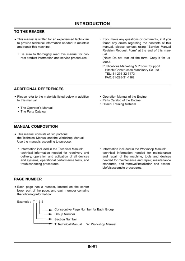
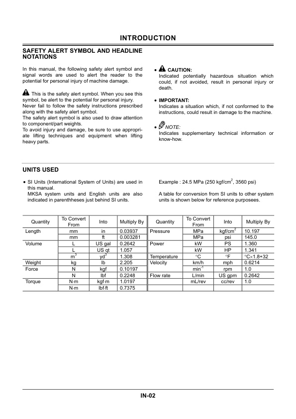
INTRODUCTION
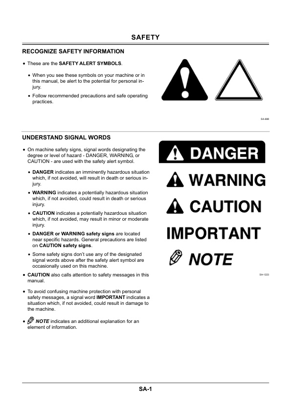
SAFETY
ALL CONTENTS
SECTION 1 GENERAL INFORMATION
Group 1 Precautions for Disassembling and Assembling
Precautions for Disassembling and Assembling
Maintenance Standard Terminology
Group 2 Tightening
Tightening Torque Specifications
Torque Chart
Piping Joint
Periodic Replacement of Parts
Group 3 Painting
Painting
Group 4 Bleeding Air
Bleed Air from Hydraulic Oil Tank
Group 5 Floor-Tilting Device
Floor-Tilting Device Operetion Procedure
Procedure for Floor Tilting up
Procedure for Floor Tilting down
SECTION 2 UPPERSTRUCTURE
Group 1 Canopy
Remove and Install Canopy
Group 2 Counterweight
Remove and Install Counterweight
Group 3 Pump Device
Remove and Install Pump Device
Disassemble Pump Device
Assemble Pump Device
Maintenance Standard
Group 4 Control Valve
Remove and Install Control Valve
Disassemble And Assemble Control Valve
Remove and Install Relief Valve and Make-up Valve
Disassemble and Assemble Body
Disassemble Unload Section
Assemble Unload Section
Disassemble and Assemble Spool
Disassemble and Assemble Boom Anti-Drift Valve
Disassemble and Assemble Shuttle Valve and Pressure Compensation Valve
Group 5 Swing Device
Remove and Install Swing Device
Disassemble Swing Device
Assemble Swing Device
Disassemble Swing Motor
Assemble Swing Motor
Maintenance Standards
Group 6 Pilot Valve
Remove and Install Front Pilot Valve
Remove and Install Travel Pilot Valve
Remove and Install Blade Pilot Valve
Remove and Install Boom Swing Pilot Valve
Disassemble Front Pilot Valve
Assemble Front Pilot Valve
Disassemble Travel Pilot Valve
Assemble Travel Pilot Valve
Disassemble Pilot Valves for Boom Swing, Blade and Auxiliary
Assemble Pilot Valves for Boom Swing, Blade and Auxiliary
Group 7 Solenoid Valve
Remove and Install 2-Unit Solenoid Valve
Disassemble 2-Unit Solenoid Valve
Assemble 2-Unit Solenoid Valve
Remove and Install 1-Unit Solenoid Valve
Structure of 1-Unit Solenoid Valve
Group 8 Revolution Sensing Valve
Remove and Install Revolution Sensing Valve
Disassemble Revolution Sensing Valve
Assemble Revolution Sensing Valve
Group 9 Auxiliry Flow Selector Valve (Optional)
Remove and Install Auxiliary Flow Selector Valve
Disassemble Auxiliary Flow Selector Valve
Assemble Auxiliary Flow Selector Valve
SECTION 3 UNDERCARRIAGE
Group 1 Swing Bearing
Remove and Install Swing Bearing
Group 2 Travel Device
Remove and Install Travel Device
Disassemble Travel Device
Assemble Travel Device
Disassemble and Assemble Brake Valve
Maintenance Standard
Group 3 Center Joint
Remove and Install Center Joint
Disassemble Center Joint
Assemble Center Joint
Group 4 Track Adjuster
Remove and Install Track Adjuster
Disassemble Track Adjuster
Assemble Track Adjuster
Group 5 Front Idler
Remove and Install Front Idler
Disassemble and Assemble Front Idler
Maintenance Standard
Group 6 Upper and Lower Roller
Remove and Install Upper Roller
Remove and Install Lower Roller
Disassemble and Assemble Lower Roller
Maintenance Standard
Group 7 Track
Remove and Install Rubber Track
Maintenance Standard
SECTION 4 FRONT ATTACHMENT
Group 1 Front Attachment
Remove and Install Front Attachment
Maintenance Standards
Group 2 Cylinder
Remove and Install Cylinders
Disassemble Boom Cylinder
Assemble Boom Cylinder
Disassemble Arm Cylinder
Assemble Arm Cylinder
Disassemble Bucket Cylinder
Assemble Bucket Cylinder
Disassemble Boom Swing Cylinder
Assemble Boom Swing Cylinder
Disassemble Blade Cylinder
Assemble Blade Cylinder
Maintenance Standards
SECTION 5 ENGINE AND ACCESSORY
PREFACE
SAFETY LABELS
CONTENTS
1. General
1.1 Engine nomenclature
1.2 Specifications
1.3 Fuel oil, lubricating oil and cooling water
1.3.1 Fuel oil
1.3.2 Lubricating oil
1.3.3 Cooling water
1.4 Engine external views
1.5 Structural description
1.6 Exhaust gas emission regulation
1.6.1 The emission standard in USA
1.6.2 Engine identification
1.6.3 Guarantee conditions for the EPA emission standard
2. Inspection and adjustment
2.1 Periodic maintenance schedule
2.2 Periodic inspection and maintenance procedure
2.2.1 Check before daily operation
2.2.2 inspection after initial 50 hours operation
2.2.3 Inspection every 50 hours
2.2.4 Inspection every 250 hours or 3 months
2.2.5 Inspection every 500 hours or 6 months
2.2.6 Inspection every 1,000 hours or one year
2.2.7 Inspection every 2000 hours or 2 years
2.3 Adjusting the no-load maximum or minimum speed
2.4 Sensor inspection
2.4.1 Oil pressure switch
2.4.2 Thermo switch
2.5 Water leak check in cooling water system
2.6 Radiator cap inspection
2.7 Thermostat Inspection
2.8 Adjusting operation
2.9 Long storage
3. Troubleshooting
3.1 Preparation before troubleshooting
3.2 Quick reference table for troubleshooting
3.3 Troubleshooting by measuring compression pressure
4. Disassembly, inspection and reassembly of engines
4.1 Complete disassembly and reassembly
4.1.1 Introduction
4.1.2 Special service tools
4.1.3 Complete disassembly
4.1.4 Precautions before and during reassembly
4.1.5 Adjusting operation
4.2 Cylinder head: Disassembly, inspection and reassembly
4.2.1 Components (2-valve cylinder head)
4.2.2 Disassembly procedure:
4.2.3 Reassembly procedure:
4.2.4 Servicing points
4.2.5 Parts Inspection and measurement
4.2.6 Valve seat correction
4.2.7 Valve guide replacement
4.2.8 Valve stem seal replacement
4.3 Gear train and camshaft
4.3.1 Components
4.3.2 Disassembly procedure:
4.3.3 Reassembly procedure:
4.3.4 Servicing points
4.3.5 Parts inspection and measurement
4.3.6 Oil seal replacement (Gear case side)
4.3.7 Camshaft bushing replacement
4.4 Cylinder block
4.4.1 Components
4.4.2 Disassembly procedure:
4.4.3 Reassembly procedure:
4.4.4 Servicing points
4.4.5 Parts inspection and measurement
4.4.6 Cylinder bore correction
4.4.7 Piston pin bushing replacement
4.4.8 Oil seal replacement (Flywheel housing side)
5. Lubrication system
5.1 Lubrication system diagram
5.2 Trochoid pump components
5.3 Disassembly (Reverse the procedure below for assembly)
5.4 Servicing points
5.5 Parts Inspection and measurement
5.5.1 Trochoid pump inspection and measurement
6. Cooling system
6.1 Cooling water system
6.2 Cooling water pump components
6.3 Disassembly (Reverse the procedure below for assembly)
6.4 Servicing points
7. Fuel injection pump / Governor
7.1 Introduction
7.2 Fuel injection pump
7.2.1 Fuel system diagram
7.2.2 External view and components
7.2.3 Disassembly procedure:
7.2.4 Assembly procedure
7.2.5 Servicing points
7.2.6 C.S.D. (Cold Start Device)
8. Turbocharger: Disassembly, inspection and reassembly
8.1 Structure and functions
8.1.1 Main specifications
8.1.2 Construction
8.1.3 Structural and functional outline
8.1.4 Components
8.2 Service standards and tightening torque
8.2.1 Service standards
8.2.2 Tightening torque
8.3 Periodic inspection procedure
8.3.1 Periodic inspection intervals
8.3.2 Inspection procedure
8.3.3 Waste gate valve adjustment procedure
8.4 Disassembly procedure
8.4.1 Preparation for disassembly
8.4.2 Inspection before disassembly
8.4.3 Disassembly
8.5 Washing and inspection procedure
8.5.1 Washing
8.5.2 Inspection procedure
8.6 Reassembly procedure
8.6.1 Preparation for reassembly
8.6.2 Reassembly
8.7 Handling after disassembly and reassembly
8.7.1 Instructions for turbocharger installation
8.8 Troubleshooting
8.8.1 Excessively exhaust smoke
8.8.2 White smoke generation
8.8.3 Sudden oil decrease
8.8.4 Decrease in output
8.8.5 Poor (slow) response (starting) of turbocharger
8.8.6 Abnormal sound or vibration
9. Starting motror
9.1 For 4TNV94L/ 98
9.1.1 Specifications
9.1.2 Components
9.1.3 Troubleshooting
9.1.4 Names of parts and disassembly procedure
9.1.5 Inspection and maintenance
9.1.6 Service standards
9.1.7 Assembly
9.1.8 Characteristic test
9.2 For 4TNV106 (T)
9.2.1 Specifications
9.2.2 Congiguration drawing
9.2.3 Troubleshooting
9.2.4 Component names and disassembly procedure
9.2.5 Disassembly procedure
9.2.6 Inspection and maintenance
9.2.7 Assembly
9.2.8 Adjustment
9.2.9 Service standards
10. Alternator
10.1 The 40A alternator for 3TNV84 and other models
10.1.1 Components
10.1.2 Specifications
10.1.3 Wiring diagram
10.1.4 Standard output characteristics
10.1.5 Inspection
10.1.6 Troubleshooting
11. Electric wiring
11.1 Electric wiring diagram
11.2 Precaution on electric wiring
11.2.1 Alternator
11.2.2 Starter
11.2.3 Current limiter
11.2.4 Section area and resistance of electric wire
12. Service standards
12.1 Engine tuning
12.2 Engine body
12.2.1 Cylinder head
12.2.2 Gear train and camshaft
12.2.3 Cylinder block
12.3 Lubricating oil system (Trochoid pump)
13. Tightening torque for bolts and nuts
13.1 Tightening torques for main bolts and nuts
13.2 Tightening torques for standard bolts and nuts
SERVICE MANUAL REVISION REQUEST FORM

There are no reviews yet.