


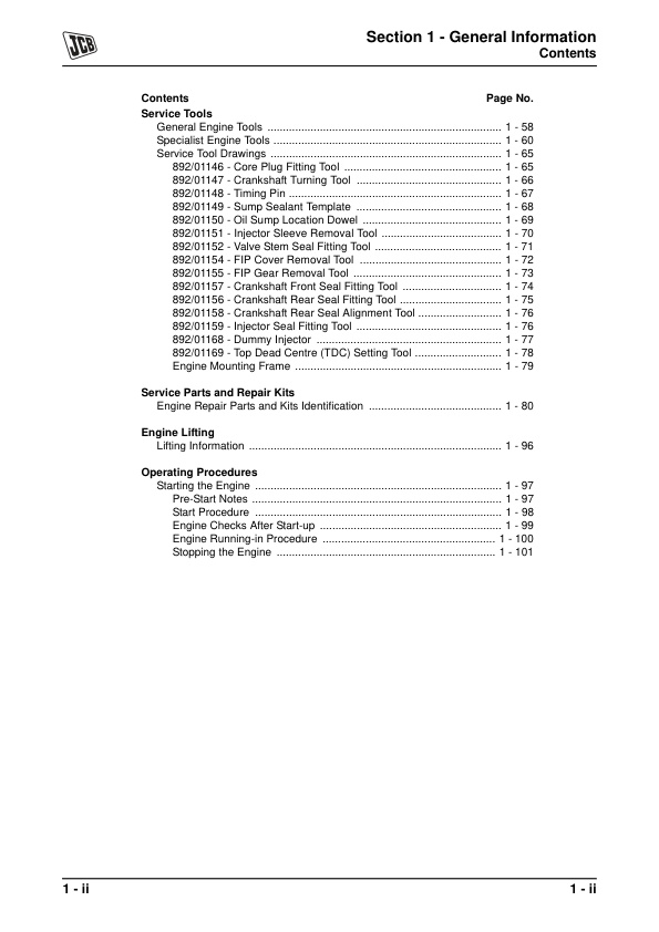

JCB 444 Engine 98063000-03 (Preview)
9806-3000
Section1
– General Information
– Introduction
— About this Manual
— Using the Service Manual
— Section Numbering
— Left Side, Right Side
— Units of Measurement
— Machine Related Data
— Acronyms and Abbreviations
– Identifying the Engine
— Engine Identification Plate
— Engine Labels
— Component Labels
— Engine Identification Number Explanation
— Engine Component Identification
– Technical Data
— Basic Engine Data
— Engine Block & Bedplate Data
— Cylinder Head Data
— Inlet and Exhaust Valve Data
— Rocker Levers, Rocker Shaft and Tappets Data
— Pistons and Connecting Rods Data
— Crankshaft Data
— Camshaft Data
— Fuel System Data
— Acceptable and Unacceptable Fuels
— Fuel Types
— Usage and Effects of Fuels
— Sulphur Content
— Effects of Fuel Contaminates
— Lubrication System Data
— Cooling System Data
— Electrical Equipment Data
– Torque Settings
— Zinc Plated Fasteners and Dacromet Fasteners
— Introduction
— Bolts and Screws
— Hydraulic Connections
— ‘O’ Ring Face Seal System
— ‘Torque Stop’ Hose System
— Torque + Angle Explanation
— Torque + Angle Tightening Procedure
— Engine Torque Figures
– Lubricants and Capacities
— Engine Lubricating Oil
— Recommended Oils
— Engine Oil Capacity
— Coolant Mixtures
– Service Aids
— Sealing, Retaining and Care Compounds
– Service Tools
— General Engine Tools
— Specialist Engine Tools
— Service Tool Drawings
— 892/01146 – Core Plug Fitting Tool
— 892/01147 – Crankshaft Turning Tool
— 892/01148 – Timing Pin
— 892/01149 – Sump Sealant Template
— 892/01150 – Oil Sump Location Dowel
— 892/01151 – Injector Sleeve Removal Tool
— 892/01152 – Valve Stem Seal Fitting Tool
— 892/01154 – FIP Cover Removal Tool
— 892/01155 – FIP Gear Removal Tool
— 892/01157 – Crankshaft Front Seal Fitting Tool
— 892/01156 – Crankshaft Rear Seal Fitting Tool
— 892/01158 – Crankshaft Rear Seal Alignment Tool
— 892/01159 – Injector Seal Fitting Tool
— 892/01168 – Dummy Injector
— 892/01169 – Top Dead Centre (TDC) Setting Tool
— Engine Mounting Frame
– Service Parts and Repair Kits
— Engine Repair Parts and Kits Identification
– Engine Lifting
— Lifting Information
– Operating Procedures
— Starting the Engine
— Pre-Start Notes
— Start Procedure
— Engine Checks After Start-up
— Engine Running-in Procedure
— Stopping the Engine
Section10
– Electrical System
– Starter Motor
— Removal and Replacement
— Before Removing
— Removal
— Inspection
— Replacement
— Dismantling and Assembly
– Alternator
— Removal and Replacement
— Before Removing
— Removal
— Inspection
— Replacement
— After Replacing
— Dismantling and Assembly
– Electric Shut-Off Solenoid (ESOS)
— Removal and Replacement
— Before Removing
— Removal
— Inspection
— Replacement
– Cold Start Advance Solenoid
— Removal and Replacement
— Before Removing
— Removal
— Inspection
— Replacement
– Engine Cold Start Switch
— Removal and Replacement
— Before Removing
— Removal
— Inspection
— Replacement
— After Replacing
– Engine Oil Pressure Switch
— Removal and Replacement
— Before Removing
— Removal
— Inspection
— Replacement
– Coolant Temperature Sender Unit
— Removal and Replacement
— Before Removing
— Removal
— Inspection
— Replacement
— After Replacing
Section11
– Induction and Exhaust System
– Turbocharger
— Removal and Replacement
— Before Removing
— Removal
— Inspection
— Replacement
— After Replacing
— Dismantling and Assembly
— Dismantling
— Assembly
– Exhaust Manifold
— Removal and Replacement
— Before Removing
— Removal
— Inspection
— Replacement
— After Replacing
– Inlet Manifold
— Removal and Replacement
— Before Removing
— Removal
— Inspection
— Replacement
Section2
– Care and Safety
– Safety Notices
— Introduction
— Safety Checklist
— General Safety
— Operating Safety
— Maintenance Safety
Section3
– Routine Maintenance
– Routine Maintenance
— Introduction
— Maintenance Procedures
— Cleaning the Engine
— High Pressure Cleaning
— Lubricants – Health and Safety
— Hygiene
— Storage
— Waste Disposal
— First Aid – Oil
— Spillage
— Fires
— Service Schedules
— Engine Oil and Filter
— Checking the Oil Level
— Changing the Oil and Filter
— Engine Cooling System
— Coolant Mixtures
— Checking the Coolant Level
— Changing the Coolant
— Front End Accessory Drive (FEAD) Belt
— Engine Fuel System
— Draining the Water Separator and Fuel Filter
— Changing the Filter Element
— Changing the Water Separator Pre- Filter
— Bleeding the Fuel System
— Air Intake System
— Engine Breather
— Cleaning the Engine Breather Gauze
Section4
– Systems Description
– Engine Overview
— Component Identification
— External
— Internal
— Basic Description
— The Four Stroke Cycle
— Camshaft and Valve Operation
— The Four Cylinder Cycle – JCB 444 Engine
— Firing Order
— Timing Gears
— Timing
— Valve Train
— Front End Accessory Drive (FEAD) Belt System
– Lubrication System
— Basic Description
— Oil Pump
— Oil Cooler and Filter
— Oil Cooler Matrix
— Oil Filter
— Camshaft Lubrication
— Crankshaft Lubrication
— Rocker Assembly Lubrication
— Piston Cooling and Small End Bearing Lubrication
– Fuel System
— Basic Description
— Pre-Filter/Water Separator, Lift Pump and Fuel Filter
— Pre Filter/Water Separator
— Lift Pump
— Fuel Filter
— Fuel Injection Pump – Injection Cycle
— State A – Charging
— State B – Injecting
— Fuel Injector Pump – Governor
— State A – Increasing Engine Speed
— State B – Decreasing Engine Speed
— Features of the Delphi DP210 Fuel Injection Pump
— Cold Start Advance – Shown at A
— Hydraulic Light Load Advance
— Variable Fuelling – Shown at B
— Latch Valve
— ESOS – Electric Shut Off Solenoid
— Turbo Boost Control (Turbocharged engines only)
— Injectors and Combustion
— Injectors
— Combustion
– Induction, Exhaust and Breather Systems
— Induction and Exhaust Systems
— Naturally Aspirated
— Turbocharged
— Intercooled
— Engine Breather
– Cooling System
— Description
— Thermostat
— State A – `Closed’ – Engine Cooled
— State B – `Open’ – Engine Hot
— Injectors
— Coolant Pump
– Electrical System
— Electrical Circuit Schematic
— Electrical Components
Section5
– Fault Finding
– Fault Finding
— Introduction
— Fault Finding Charts
— A Charts – Engine
— B Charts – Fuel
— C Charts – Lubricating Oil
— D Charts – Coolant
Section6
– Test Procedures
– Introduction
— Test Procedures Introduction
– Testing
— Lift Pump Operation
— Pressure Test Procedures
— Measuring the Inlet Restriction
— Fuel Injection Pump Delivery
— Engine Compression
— Engine Oil Pressure
— High Lubrication Oil Pressure
— Low Lubrication Oil Pressure
— Thermostat
— Air System and Turbocharger
— Air Filters
— Air Intake Connections
— Exhaust Manifold Leaks (Turbocharged Engines)
— Turbocharger Checks
— Wastegate Operational Check
— Using a Multimeter
— Measuring DC Voltage
— Measuring Resistance
— Measuring Continuity
— Measuring Frequency
— Testing a Diode or a Diode Wire
— Battery
— Maintenance
—- First Aid – Electrolyte
— Testing
— Specific Gravity Testing
— Alternator
— General Description
— Service Precautions
— Charging Circuit Test
— Alternator Charging Test
— Starter Motor
— Starting Circuit Test
Section7
– Fuel System
– Fuel Filter
— Removal and Replacement
– Fuel Lines
— Identification
— Removal and Replacement
— High Pressure Fuel Lines
— Low Pressure Fuel Lines
— Fuel Bleed-off Lines (Low Pressure)
– Fuel Lift Pump
— Removal and Replacement
— Removal
— Replacement
– Fuel Injection Pump
— Removal and Replacement
— Component Identification
— Before Removing:
— Removal
— Replacement
— After Replacing
– Fuel Injectors (Atomisers)
— Removal and Replacement
— Removal
— Replacement
– Bleeding Air From The System
— Bleeding Air From The System
Section8
– Cooling System
– Drive Belt – Coolant Pump
— Front End Accessory Drive Belt (FEAD)
— Removal and Replacement
– Thermostat
— Removal and Replacement
— Before Removing
— Removal
— Replacement
— After Replacing
– Coolant Inlet Assembly
— Removal and Replacement
— Before Removing
— Removal
— Replacement
— After Replacing
– Coolant Pump
— Removal and Replacement
— Before Removing
— Removal
— Replacement
— After Replacing
– Lubricating Oil Cooler
— Removal and Replacement
Section9
– Lubrication System
– Oil Filter Head
— Removal and Replacement
– Oil Pan (Sump)
— Removal and Replacement
— Before Removing
— Removal
— Replacement
— After Replacing
– Oil Pump
— Removal and Replacement
— Before Removing
— Removal
— Inspection
— Replacement
— After Replacing
– Lubricating Oil Cooler and Filter Head
— Removal and Replacement
— Before Removing
— Removal
— Replacement
— After Replacing
— Dismantling, Inspection and Assembly
— Dismantling
— Inspection
— Assembly

Reviews
There are no reviews yet.