Komatsu D85EX-15R, D85PX-15R 20001 & Up SEN02947-03 (Preview)
COVER
00 Index and foreword
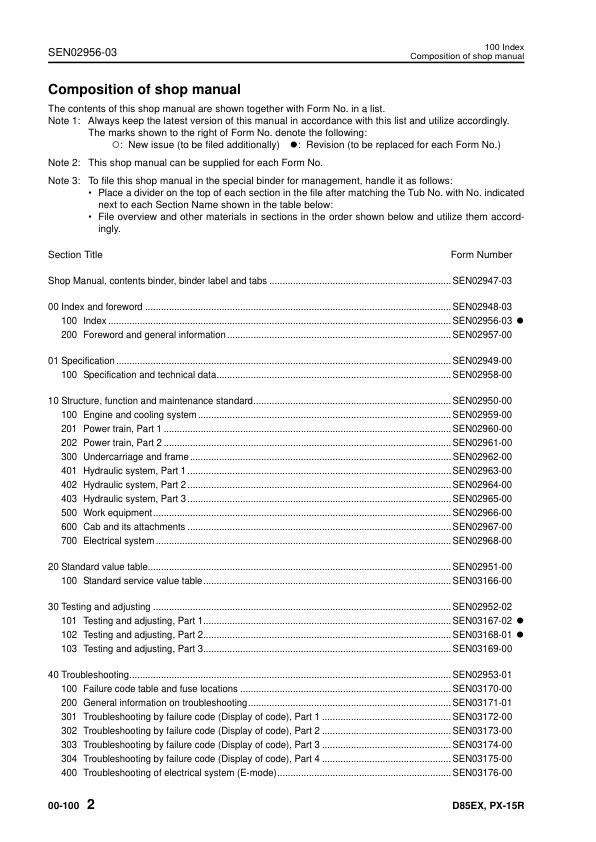
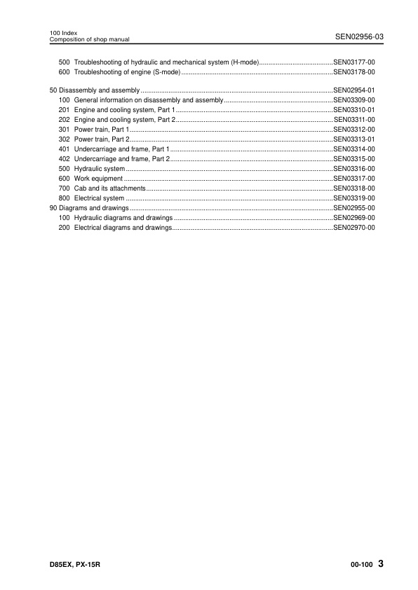
100 Index
Composition of shop manual
Table of contents
200 Foreword and general information
Safety notice
How to read the shop manual
Explanation of terms for maintenance standard
Handling of electric equipment and hydraulic component
Handling of connectors newly used for engines
How to read electric wire code
Precautions when carrying out operation
Method of disassembling and connecting push-pull type coupler
Standard tightening torque table
Conversion table
01 Specification
100 Specification and technical data
Specification dimensions
Specifications
Weight table
Table of fuel, coolant and lubricants
10 Structure, function and maintenance standard
100 Engine and cooling system
Engine mount
Cooling system
Cooling fan pump
Cooling fan motor
201 Power train, Part 1
Power train
HSS system
General view of power train unit
Power train hydraulic piping drawing
Transmission control
Steering and brake control
Damper and universal joint
Torque converter and PTO
Transmission
Transmission clutch ECMV
Main relief valve and torque converter relief valve
Lubrication relief valve
202 Power train, Part 2
Bevel gear shaft, HSS and brake
Brake valve
Final drive
300 Undercarriage and frame
Main frame
Suspension
Track frame
Idler cushion
Idler
Track roller
Carrier roller
Sprocket
Track shoe
401 Hydraulic system, Part 1
Work equipment hydraulic piping diagram
PPC control piping diagram
Work equipment control
Hydraulic tank and filter
Scavenging pump
Power train and steering lubrication pump
HSS pump
HSS motor
402 Hydraulic system, Part 2
Control valve
Self pressure reducing valve
403 Hydraulic system, Part 3
Oil cooler bypass valve
PPC valve
Electric lever (steering)
Quick drop valve
PPC lock valve
Accumulator
500 Work equipment
Cylinder stay
Blade
Cutting edge and end bit
Ripper
Hydraulic cylinder
Piston valve
600 Cab and its attachments
Cab mount
Cab
Air conditioner
700 Electrical system
Monitor system
Monitor panel
Engine control
Engine control system
System components
CRI engine control system
Palm command control system
KOMTRAX system
Sensor
20 Standard value table
100 Standard service value table
Standard service value table for engine
Standard service value table for chassis
30 Testing and adjusting
101 Testing and adjusting, Part 1
Tools for testing, adjusting, and troubleshooting
Measuring engine speed
Measuring intake air pressure (boost pressure)
Measuring exhaust temperature
Measuring exhaust gas color
Adjusting valve clearance
Measuring compression pressure
Measuring blow-by pressure
Measuring engine oil pressure
Handling of fuel system devices
Releasing residual pressure from fuel system
Testing fuel pressure
Handling of reduced cylinder mode operation
Handling of no injection cranking operation
Testing fuel return and leak amount
Bleeding air from fuel circuit
Testing and adjusting alternator belt tension
Testing and adjusting air conditioner compressor belt tension
Adjusting fuel control dial and decelerator pedal
Measuring power train oil pressure
Adjusting transmission speed sensor
Simple method to test brake performance
Adjusting brake pedal
Adjusting parking brake lever
Emergency escape method when power train has trouble
Adjusting clearance of idler
Inspecting wear of sprocket
Testing and adjusting track shoe tension
Testing and adjusting work equipment and HSS oil pressure
Testing control circuit basic pressure
Measuring PPC valve output pressure
Adjusting work equipment PPC valve play
Checking parts which caused hydraulic drift of blade and ripper
Measuring internal leakage of work equipment cylinder
Bleeding air from work equipment cylinder
Releasing residual pressure in work equipment cylinder
Adjusting work equipment lock lever
Measuring fan motor speed
Measuring fan pump circuit pressure
Bleeding air from fan pump
Adjusting blade
Testing and adjusting operator cab
102 Testing and adjusting, Part 2
Special functions of monitor panel (EMMS)
103 Testing and adjusting, Part 3
Adjustment method when controller has been replaced
Preparation work for troubleshooting for electrical system
Inspection procedure of diode
Handing of optional devices
Pm Clinic service
How to start operation of KOMTRAX terminal
Lamp display of KOMTRAX terminal
40 Troubleshooting
100 Failure code table and fuse locations
Failure code table
Before troubleshooting by failure codes
200 General information on troubleshooting
Points to remember when troubleshooting
How to proceed troubleshooting
Checks before troubleshooting
Classification and procedures of troubleshooting
Contents of troubleshooting table
Connection table for connector pin numbers
T- branch box and T- branch adapter table
301 Troubleshooting by failure code (Display of code), Part 1
Failure code [1500L0] Transmission clutch: Dual engagement
Failure code [15SAL1] Forward clutch: Fill signal is ON when command current is OFF
Failure code [15SALH] Forward clutch: Fill signal is OFF when command current is ON
Failure code [15SBL1] Reverse clutch: Fill signal is ON when command current is OFF
Failure code [15SBLH] Reverse clutch: Fill signal is OFF when command current is ON
Failure code [15SEL1] 1st clutch: Fill signal is ON when command current is OFF
Failure code [15SELH] 1st clutch: Fill signal is OFF when command current is ON
Failure code [15SFL1] 2nd clutch: Fill signal is ON when command current is OFF
Failure code [15SFLH] 2nd clutch: Fill signal is OFF when command current is ON
Failure code [15SGL1] 3rd clutch: Fill signal is ON when command current is OFF
Failure code [15SGLH] 3rd clutch: Fill signal is OFF when command current is ON
Failure code [A000NS] Engine overheat
Failure code [AA10NX] Air cleaner: Clogged
Failure code [AB00MA] Abnormal battery charge: Malfunction
Failure code [B@BAZG] Engine oil: Oil pressure too low
Failure code [B@BAZK] Engine oil level reduction
Failure code [B@BCNS] Radiator coolant: Overheat
Failure code [B@BCZK] Radiator coolant: Level too low
Failure code [B@BEBF] Water in engine fuel
Failure code [B@BFZK] Fuel level reduction
Failure code [B@CENS] Power train oil: Overheat
Failure code [B@CHZG] HSS charge oil pressure reduction
Failure code [B@CHZK] Power train oil level reduction
Failure code [B@GAZK] Battery electrolyte level reduction
Failure code [B@HANS] Hydraulic oil: Overheat
Failure code [B@HAZK] Hydraulic oil level reduction
Failure code [CA111] Engine controller: Abnormality in controller
Failure code [CA115] Abnormal engine Ne and Bkup speed sensors: Abnormal speed sensor signal
Failure code [CA122] Charge pressure sensor too high: Excessively high voltage detected
Failure code [CA123] Charge pressure sensor too low: Excessively low voltage detected
Failure code [CA131] Decelerator pedal sensor too high: Excessively high voltage detected
Failure code [CA132] Decelerator pedal sensor too low: Excessively low voltage detected
Failure code [CA135] Oil pressure sensor too high: Excessively high voltage detected
Failure code [CA141] Oil pressure sensor too low: Excessively low voltage detected
Failure code [CA144] Coolant temperature sensor too high: Excessively high voltage detected
Failure code [CA145] Coolant temperature sensor too low: Excessively low voltage detected
Failure code [CA153] Charge temperature sensor too high: Excessively high voltage detected
Failure code [CA154] Charge temperature sensor too low: Excessively low voltage detected
Failure code [CA187] Sensor power source 2 too low: Low voltage detected
Failure code [CA221] Atmospheric pressure sensor too high: Excessively high voltage detected
Failure code [CA222] Atmospheric pressure sensor too low: Excessively low voltage detected
Failure code [CA227] Sensor power source 2 too high: Excessively high voltage detected
Failure code [CA234] Engine over speed: Excessively high speed
Failure code [CA238] Abnormal power source for Ne speed sensor: Excessively low voltage detected
Failure code [CA263] Fuel temperature sensor too high: Excessively high voltage detected
Failure code [CA265] Fuel temperature sensor too low: Excessively low voltage detected
Failure code [CA271] PCV1 short circuit: Short circuit
Failure code [CA272] PCV1 disconnection: Disconnection
Failure code [CA273] PCV2 short circuit: Short circuit
Failure code [CA274] PCV2 disconnection: Disconnection
302 Troubleshooting by failure code (Display of code), Part 2
Failure code [CA322] Injector No. 1 system disconnection or short circuit: Disconnection, short circuit
Failure code [CA323] Injector No. 5 system disconnection or short circuit: Disconnection, short circuit
Failure code [CA324] Injector No. 3 system disconnection or short circuit: Disconnection, short circuit
Failure code [CA325] Injector No. 6 system disconnection or short circuit: Disconnection, short circuit
Failure code [CA331] Injector No. 2 system disconnection or short circuit: Disconnection, short circuit
Failure code [CA332] Injector No. 4 system disconnection or short circuit: Disconnection, short circuit
Failure code [CA342] Engine controller data matching error: Matching error
Failure code [CA351] Abnormal injector drive circuit: Abnormal circuit
Failure code [CA352] Sensor power source (1) too low: Excessively low voltage detected
Failure code [CA386] Sensor power source (1) too high: Excessively high voltage detected
Failure code [CA441] Power source voltage too low: Excessively low voltage detected
Failure code [CA442] Power source voltage too high: Excessively high voltage detected
Failure code [CA449] Common rail pressure too high (2): Excessively high pressure trouble occurred
Failure code [CA451] Common rail pressure sensor too high: Excessively high voltage detected
Failure code [CA452] Common rail pressure sensor too low: Excessively low voltage detected
Failure code [CA553] Common rail pressure too high (1): Excessively high pressure detected
Failure code [CA554] In-range error in common rail pressure sensor: In-range error
Failure code [CA559] Loss of pressure feed from supply pump (1): Loss of pressure feed detected
Failure code [CA689] Abnormal engine Ne speed sensor: Abnormal signal
Failure code [CA731] Abnormal engine Bkup speed sensor phase: Abnormal phase
Failure code [CA757] Loss of all engine controller data: Loss of all data
Failure code [CA778] Abnormal engine Bkup speed sensor: Abnormal Bkup signal
Failure code [CA1633] Abnormal KOMNET: Abnormal communication
Failure code [CA2185] Decelerator pedal sensor power source too high: Excessively high voltage detected
Failure code [CA2186] Decelerator pedal sensor power source too low: Excessively low voltage detected
Failure code [CA2249] Loss of pressure feed from supply pump (2): Loss of pressure feed detected
Failure code [CA2555] Intake air heater relay disconnection: Disconnection
Failure code [CA2556] Intake air heater relay short circuit: Short circuit
303 Troubleshooting by failure code (Display of code), Part 3
Failure code [D110KA] Battery relay: Disconnection
Failure code [D110KB] Battery relay: Short circuit
Failure code [D130KA] Neutral safety relay: Disconnection
Failure code [D130KB] Neutral safety relay: Short circuit
Failure code [D161KA] Back-up alarm relay: Disconnection
Failure code [D161KB] Back-up alarm relay: Short circuit
Failure code [D190KA] Engine controller ACC signal cutout relay: Disconnection
Failure code [D190KB] Engine controller ACC signal cutout relay: Short circuit
Failure code [D811KR] KOMTRAX controller CAN communication: Defective communication
Failure code [DAFRKR] Monitor panel CAN communication: Defective communication
Failure codes [DAQ0KT] and [DB30KT] Steering and transmission controller: Abnormal controller memory information
Failure code [DAQ1KK] [DB31KK] Main power source of steering and transmission controller: Power source voltage drop and input
Failure code [DAQ2KK] [DB32KK] Load power source of steering and transmission controller: Power source voltage drop and input
Failure codes [DAQ5KK] and [DB35KK] Steering and transmission controller sensor 5 V power source (1): Power source voltage drop and input
Failure code [DAQ6KK] [DB36KK] Steering and transmission controller sensor 24 V power source: Power source voltage drop and input
Failure codes [DAQ7KK] and [DB37KK] Steering and transmission controller sensor 5 V power source (2): Power source voltage drop and input
Failure code [DAQ9KQ] [DB39KQ] Steering and transmission controller model selection: Inconsistency in model select signal
Failure codes [DAQRKR] and [DB3RKR] Steering and transmission controller CAN communication: Defective communication
Failure code [DB2RKR] Engine controller CAN communication: Defective communication
Failure code [DB30KT] [DAQ0KT] Steering and transmission controller: Abnormal controller memory information
Failure code [DB31KK] [DAQ1KK] Main power source of steering and transmission controller: Power source voltage drop and input
Failure code [DB32KK] [DAQ2KK] Load power source of steering and transmission controller: Power source voltage drop and input
Failure codes [DB35KK] and [DAQ5KK] Steering and transmission controller sensor 5 V power source (1): Power source voltage drop and input
Failure code [DB36KK] [DAQ6KK] Steering and transmission controller sensor 24 V power source: Power source voltage drop and input
Failure codes [DB37KK] and [DAQ7KK] Steering and transmission controller sensor 5 V power source (2): Power source voltage drop and input
Failure codes [DB39KQ] and [DAQ9KQ] Steering and transmission controller model selection: Inconsistent model selection signal
Failure codes [DB3RKR] and [DAQRKR] Steering and transmission controller CAN communication: Defective communication
Failure code [DD12KA] Shift up switch: Disconnection
Failure code [DD12KB] Shift up switch: Short circuit
Failure code [DD13KA] Shift down switch: Disconnection
Failure code [DD13KB] Shift down switch: Short circuit
Failure codes [DD14KA] and [DDQ2KA] Parking lock switch: Disconnection
Failure codes [DD14KB] and [DDQ2KB] Parking lock switch: Short circuit
Failure codes [DDQ2KA] and [DD14KA] Parking lock switch: Disconnection
Failure codes [DDQ2KB] and [DD14KB] Parking lock switch: Short circuit
Failure code [DGS1KX] Hydraulic oil temperature sensor: Input signal is out of normal range
Failure code [DGT1KA] Power train oil temperature sensor: Disconnection
Failure code [DGT1KX] Power train oil temperature sensor: Input signal is out of normal range
Failure code [DH22KA] HSS and work equipment pump oil pressure sensor: Disconnection
Failure code [DH22KB] HSS and work equipment pump oil pressure sensor: Short circuit
Failure code [DK10KA] Fuel dial: Disconnection
Failure code [DK10KB] Fuel dial: Short circuit
Failure code [DK30KA] Steering potentiometer (1): Disconnection
Failure code [DK30KB] Steering potentiometer (1): Short circuit
Failure code [DK30KX] Steering potentiometer: Input signal is out of normal range
Failure code [DK30KZ] Steering potentiometer: Disconnection or short circuit (Double failure)
Failure code [DK30L8] Steering potentiometer: Inconsistent analog signal
Failure code [DK31KA] Steering potentiometer (2): Disconnection
Failure code [DK31KB] Steering potentiometer (2): Short circuit
Failure code [DK40KA] Brake potentiometer: Disconnection
Failure code [DK40KB] Brake potentiometer: Short circuit
Failure code [DK55KX] Forward-reverse potentiometer: Input signal is out of normal range
Failure code [DK55KZ] Forward-reverse potentiometer: Disconnection or short circuit (Double failure)
Failure code [DK55L8] Forward-reverse potentiometer: Inconsistent analog signal
Failure code [DK56KB] Forward-reverse potentiometer (1): Short circuit
Failure code [DK56KA] Forward-reverse potentiometer (1): Disconnection
Failure code [DK57KA] Forward-reverse potentiometer (2): Disconnection
Failure code [DK57KB] Forward-reverse potentiometer (2): Short circuit
304 Troubleshooting by failure code (Display of code), Part 4
Failure code [DKH1KA] [DKH1KX] Pitch angle sensor: Short circuit
Failure code [DKH1KB] [DKH1KX] Pitch angle sensor: Disconnection
Failure code [DKH1KX], [DKH1KA] or [DKH1KB] Pitch angle sensor: Input signal out of range
Failure code [DLT3KA] Transmission output speed sensor: Disconnection
Failure code [DLT3KB] Transmission output speed sensor: Short circuit
Failure code [DV00KB] Alarm buzzer: Short circuit
Failure code [DW7BKA] Fan reverse solenoid: Disconnection
Failure code [DW7BKB] Fan reverse solenoid: Short circuit
Failure code [DW7BKY] Fan reverse solenoid: Hot short circuit
Failure code [DWN1KA] HSS EPC solenoid right: Disconnection
Failure code [DWN1KB] HSS EPC solenoid right: Short circuit
Failure code [DWN1KY] HSS EPC solenoid right: Hot short circuit
Failure code [DWN2KA] HSS EPC solenoid left: Disconnection
Failure code [DWN2KB] HSS EPC solenoid left: Short circuit
Failure code [DWN2KY] HSS EPC solenoid left: Hot short circuit
Failure code [DWN5KA] Fan pump EPC solenoid: Disconnection
Failure code [DWN5KB] Fan pump EPC solenoid: Short circuit
Failure code [DWN5KY] Fan pump EPC solenoid: Hot short circuit
Failure code [DXA0KA] HSS and work equipment pump TVC solenoid: Disconnection
Failure code [DXA0KB] HSS and work equipment pump TVC solenoid: Short circuit
Failure code [DXA0KY] HSS and work equipment pump TVC solenoid: Hot short circuit
Failure code [DXH4KA] 1st clutch ECMV: Disconnection
Failure code [DXH4KB] 1st clutch ECMV: Short circuit
Failure code [DXH4KY] 1st clutch ECMV: Hot short circuit
Failure code [DXH5KA] 2nd clutch ECMV: Disconnection
Failure code [DXH5KB] 2nd clutch ECMV: Short circuit
Failure code [DXH5KY] 2nd clutch ECMV: Hot short circuit
Failure code [DXH6KA] 3rd clutch ECMV: Disconnection
Failure code [DXH6KB] 3rd clutch ECMV: Short circuit
Failure code [DXH6KY] 3rd clutch ECMV: Hot short circuit
Failure code [DXH7KA] Reverse clutch ECMV: Disconnection
Failure code [DXH7KB] Reverse clutch ECMV: Short circuit
Failure code [DXH7KY] Reverse clutch ECMV: Hot short circuit
Failure code [DXH8KA] Forward clutch ECMV: Disconnection
Failure code [DXH8KB] Forward clutch ECMV: Short circuit
Failure code [DXH8KY] Forward clutch ECMV: Hot short circuit
400 Troubleshooting of electrical system (E-mode)
Before troubleshooting of electrical system
Contents of troubleshooting table
E-1 Engine does not start.
E-2 The preheater does not operate.
E-3 The monitor panel does not light up at all when the starting switch is turned ON.
E-4 When the starting switch is turned ON, the monitor panel completely remains lighted and does not go out.
E-5 When the starting switch is turned ON, the radiator coolant level caution lamp flashes.
E-6 While the engine is running, the battery charge level caution lamp flashes.
E-7 While the engine is running, the emergency warning item flashes.
E-8 While the preheater is operating, the preheating pilot lamp does not light up.
E-9 The coolant temperature gauge does not indicate correctly.
E-10 Power train oil temperature gauge does not indicate correctly.
E-11 Hydraulic oil temperature gauge does not indicate properly.
E-12 Fuel gauge does not indicate properly.
E-13 Gear speed and engine speed are not indicated properly.
E-14 The preset mode and service meter do not indicate properly.
E-15 The warning lamp does not flash or does not go out.
E-16 The alarm buzzer does not sound or does not stop.
E-17 Auto shift down does not operate or does not release.
E-18 Buzzer cancel switch does not work.
E-19 The information switch does not work.
E-20 The manual mode does not operate or does not release.
E-21 The monitor panel cannot be set in the service mode or cannot be set out of the service mode.
E-22 The back-up alarm does not sound.
E-23 The head lamp and rear lamp do not light up.
E-24 The horn does not sound or does not stop.
E-25 Malfunction of wipers
E-26 Washer does not spray water
E-27 The air conditioner does not operate
E-28 KOMTRAX system does not operate normally.
E-29 Fan does not reverse
E-30 Gear cannot be shifted
E-31 Electric priming pump does not operate or does not stop automatically
500 Troubleshooting of hydraulic and mechanical system (H-mode)
Contents of troubleshooting table
H-1 There is no travel power (no drawbar pull)
H-2 Machine does not move (at 2nd or 3rd speed)
H-3 Machine does not move at any gear speed
H-4 Machine travels only in one direction, forward or reverse
H-5 When gear is shifted or travel direction is changed, large time lag is made
H-6 Machine cannot be steered (Machine does not turn leftward or rightward)
H-7 Steering speed or power is low
H-8 Brake does not work
H-9 Overheat of power train oil
H-10 Abnormal sound comes out from around HSS and work equipment pump or HSS motor
H-11 All work equipment speeds are slow
H-12 All work equipments do not move
H-13 Blade lift speed is slow or lacks power
H-14 Blade tilt speed is slow or lacks power
H-15 Ripper lift speed is slow or lacks power
H-16 Excessive hydraulic drift of blade lift
H-17 Excessive hydraulic drift of blade tilt
H-18 Excessive hydraulic drift of ripper lift
H-19 Fan speed is abnormal (Fan sound and vibration are abnormally large or engine overheats)
600 Troubleshooting of engine (S-mode)
Method of using troubleshooting charts
S-1 Starting performance is poor.
S-2 Engine does not start
S-3 Engine does not pick up smoothly
S-4 Engine stops during operations
S-5 Engine does not rotate smoothly
S-6 Engine lacks output (or lacks power)
S-7 Exhaust smoke is black (incomplete combustion)
S-8 Oil consumption is excessive (or exhaust smoke is blue)
S-9 Oil becomes contaminated quickly
S-10 Fuel consumption is excessive
S-11 Oil is in coolant (or coolant spurts back, or coolant level goes down)
S-12 Oil pressure drops
S-13 Oil level rises (water, fuel in oil)
S-14 Coolant temperature becomes too high (overheating)
S-15 Abnormal noise is made.
S-16 Vibration is excessive
S-17 Air cannot be bled from fuel circuit
50 Disassembly and assembly
100 General information on disassembly
How to read this manual
Coating materials list
Special tools list
Sketch of special tool
201 Engine and cooling system, Part 1
Removal and installation of fuel supply pump assembly
Removal and installation of cylinder head assembly
Removal and installation of fuel injector assembly
Removal and installation of engine front seal
Removal and installation of engine rear seal
Removal and installation of engine oil pan
202 Engine and cooling system, Part 2
Removal and installation of engine assembly
Removal and installation of radiator assembly
Removal and installation of fan drive assembly
Removal and installation of fan motor assembly
Removal and installation of fuel tank assembly
Removal and installation of damper assembly
Disassembly and assembly of damper assembly
Removal and installation of engine hood assembly
301 Power train, Part 1
Removal and installation of power train unit assembly
Disconnection and connection of power train unit assembly
Disassembly and assembly of PTO assembly
Disassembly and assembly of torque converter assembly
Disassembly and assembly of TORQFLOW transmission assembly
302 Power train, Part 2
Disassembly and assembly of HSS assembly
Removal and installation of final drive assembly
Disassembly and assembly of final drive assembly
401 Undercarriage and frame, Part 1
Removal and installation of track frame assembly
Removal and installation of idler assembly
Disassembly and assembly of idler assembly
Removal and installation of recoil spring assembly
Disassembly and assembly of recoil spring assembly
Removal and installation of track roller assembly
Disassembly and assembly of track roller assembly
Removal and installation of carrier roller assembly
Disassembly and assembly of carrier roller assembly
402 Undercarriage and frame, Part 2
Expansion and installation of track shoe assembly
Whole disassembly and whole assembly of track shoe assembly
Field disassembly and assembly of one link
Disassembly and assembly of master link
Removal and installation of pivot shaft assembly
Removal and installation of equalizer bar assembly
Disassembly and assembly of equalizer bar assembly
500 Hydraulic system
Removal and installation of work equipment control valve assembly
Disassembly and assembly of work equipment control valve assembly
Removal and installation of HSS and work equipment pump assembly
Removal and installation of power train and lubricating oil pump assembly
Removal and installation of fan pump assembly
Removal and installation of scavenging pump assembly
Removal and installation of HSS motor assembly
Disassembly and assembly of hydraulic cylinder assembly
600 Work equipment
Removal and installation of blade assembly
Disassembly and assembly of ripper assembly
700 Cab and its attachments
Removal and installation of ROPS guard assembly
Removal and installation of operator’s cab assembly
Removal and installation of operator’s cab glass (Stuck glass)
Removal and installation of floor frame assembly
800 Electrical system
Removal and installation of engine controller
Removal and installation of steering and transmission controller
Removal and installation of KOMTRAX terminal
90 Diagrams and drawings
100 Hydraulic diagrams and drawings
Power train hydraulic circuit diagram
Hydraulic circuit diagram
200 Electrical diagrams and drawings
Electrical circuit diagram (1/7)
Electrical circuit diagram (2/7)
Electrical circuit diagram (3/7)
Electrical circuit diagram (4/7)
Electrical circuit diagram (5/7)
Electrical circuit diagram (6/7)
Electrical circuit diagram (7/7)
Cab electrical circuit diagram
Air conditioner electrical circuit diagram
Connector list and stereogram

Reviews
There are no reviews yet.