Komatsu WA250-6 A76001 & Up CEBM000703 (Preview)
COVER
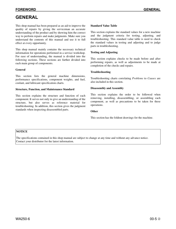
FOREWORD
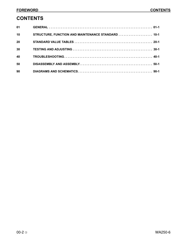
– CONTENTS
– REVISED PAGES
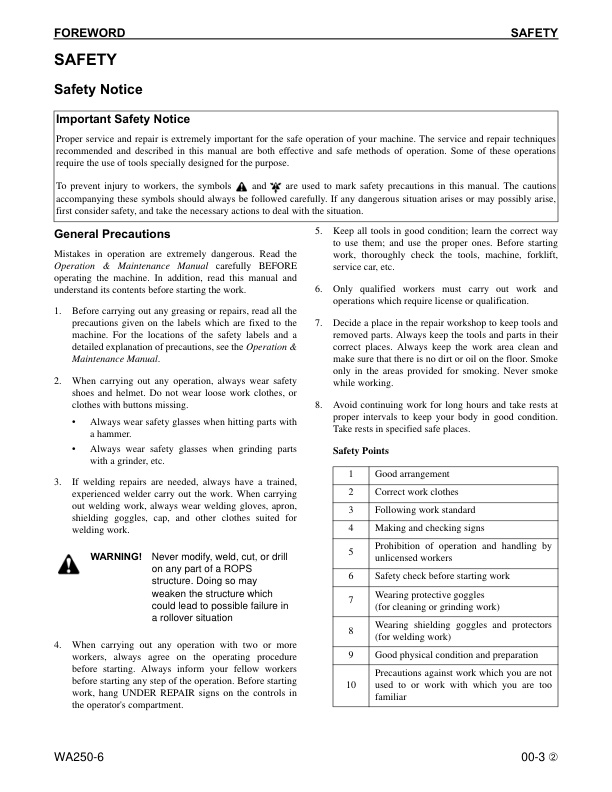
– SAFETY
— Safety Notice
— Important Safety Notice
— General Precautions
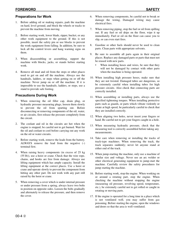
— Preparations for Work
— Precautions During Work
– GENERAL
– HOW TO READ THE SHOP MANUAL
— Volumes
— Distribution and Updating
— Filing Method
— Revised Edition Mark
— Revisions
— Symbols
– HOISTING INSTRUCTIONS
— Hoisting
— Making Signs
— Precautions
— Precautions for Sling Work
— Precautions for Using Mobile Crane
— Precautions for Using Overhead Hoist Crane
— Selecting Wire Ropes
– AIR CONDITIONER CIRCUITS
— Precautions for Handling Hoses and Tubes
— Disconnecting Hoses and Tubes
— Connecting Hoses and Tubes
– MAINTENANCE STANDARD TERMS
– HANDLING ELECTRIC AND HYDRAULIC EQUIPMENT
— Handling Electric Equipment
— Handling Wiring Harnesses and Connectors
— Main Failures Occurring in Wiring Harness
— Removing, Installing, and Drying Connectors and Wiring Harnesses
— Handling Controller
— Troubleshooting Electric Circuits
— Handling Hydraulic Equipment
— Handling Connectors Used for Engines
— Slide Lock Type
— Pull Lock Type
— Push Lock Type
— Turn-housing Type (Round Green Connector)
– PRECAUTIONS FOR OPERATIONS
— Precautions when Carrying Out Removal Work
— Precautions when Carrying Out Installation Work
— Precautions when Completing the Operation
– PUSH-PULL COUPLER
— Type 1
— Disconnection
— Connection
— Type 2
— Disconnection
— Connection
— Type 3
— Disconnection
— Connection
– COATING MATERIALS
– STANDARD TIGHTENING TORQUE
— Standard Tightening Tables
— For Bolts and Nuts
— For Split Flange Bolts
— For O-Ring Boss Piping Joints
— For O-Ring Boss Plugs
— For Hoses (Taper-Seal Type and Face-Seal Type)
— For Face Seal Joints
— For 102, 107, and 114 Engine Series (Bolts and Nuts)
— For 102, 107, and 114 Engine Series (Eye Joints)
— For 102, 107, and 114 Engine Series (Taper Screws)
– CONVERSION TABLES
— Method of Using the Conversion Table
01 GENERAL
– SPECIFICATIONS
— Dimension Drawing
— Specification Tables
– WEIGHT TABLE
– FUEL, COOLANT, AND LUBRICANTS
10 STRUCTURE, FUNCTION AND MAINTENANCE STANDARD
– ENGINE AND COOLING SYSTEM
— Engine and Transmission Mounting
— Torque Values
— Damper
— Torque Values
— Outline
— Cooling System
— Specifications
— Cooling System Hydraulic Piping Diagram
— Outline
— Cooling Fan Motor
— Type: LMF16
— Torque Values
— Specifications
— Torque Values
— Hydraulic Motor
—- Function
—- Principle of Operation
— Suction Safety Valve
—- Suction Function
—- Operation
—- Safety Function
—- Function
—- Operation
— Operation of Reversible Valve
— Flow Control Valve (Continuously Variable Type)
—- Function
—- Operation
– POWER TRAIN SYSTEM
— Drive Line Components
— System Diagram
— Outline
— Drive Shaft
— Torque Values
— Outline
— HST Hydraulic Piping Diagram
— HST Pump
— Specifications
— Operation
—- Flow of Power
—- Flow of Oil
— High-Pressure Relief Valve
—- Function
—- Operation
— Low-pressure Relief Valve
—- Function
—- Operation
— HST Charge Pump
—- Outline
—- Specifications
—- Function
— Speed-Related Valve (DA Valve)
—- Function
—- Operation
— High-Pressure Cutoff Valve
—- Function
—- Operation
— HST Motor
— HST Motor 1
—- Specifications
— HST Motor 2
—- Specifications
—- Principle
—- Structure
—- Operation
— EP Servo Valve
—- Function
—- Operation
— HA Servo Valve
—- Function
—- Operation
— Directional Shuttle Valve
—- Function
—- Operation
— Transfer
— Torque Values
— Torque Values
— Input Shaft
— Output Shaft
—- Torque Values
— Outline
—- Relation between transfer clutch and transfer clutch pressure at respective speed ranges
—- Relationship between accelerator pedal angle and travel speed (A) for starting transfer clutch switching modulation
— Operation of Clutch
—- Clutch is Engaged (fixed)
—- Clutch is Disengaged (released)
— Power Transmitting Route
—- Low-Speed Mode
—- High-Speed Mode
— Clutch Solenoid Valve
—- Operation
– DRIVE AXLE SYSTEM
— Front and Rear Axles
— Front Axle
—- Torque Values
— Rear Axle
—- Torque Values
— Differential
— Front Differential
—- Torque Values
— Rear Differential
—- Torque Values
—- Outline
—- While Machine is Traveling Straight
—- While Machine is Turning
— Torque Proportioning Differential
— Outline
— Operation
— Straight Travel (when road resistance under both tires is the same)
— Travel on Soft Ground (when road resistance under both tires is different)
— Limited Slip Differential
— Torque Values
— Operation
— Mechanism of Generation of Braking Torque by Right and Left Side Gears (5)
— While Machine is Traveling Straight (when the drive forces of the right and left wheels are balanced)
— When the drive forces of the right and left wheels are unbalanced
— Difference in wheel drive force by type of differentials when either wheel slips
— Torque Proportioning Differential
— Conventional Differential (not applicable to this machine)
— While Machine is Turning
— Final Drive
— Front Final Drive
—- Torque Values
— Rear Final Drive
—- Torque Values
—- Outline
– STEERING SYSTEM
— Steering Piping Diagram
— Steering Column
— Torque Values
— Priority Valve
— Torque Values
— Outline
— Operation
—- When Steering Wheel is at Neutral Position
—- When Steering Wheel is Turned Left
— Orbitrol Valve
— Torque Values
— Outline
— Structure
— Operation
—- When Steering Wheel is at Neutral Position
—- When Steering Wheel is Turned Left
—- When Steering Wheel is at Stop Position
— Connection of Hand Pump and Sleeve
—- Role of Centering Spring
— 2-Way Restrictor Valve
— Function
— Operation
— Cushion Valve
— Outline
— Function
— Steering Cylinder
— Torque Values
— Emergency Steering Piping Diagram
— Emergency Steering Valve
— Torque Values
— Operation
—- When Engine and Steering Pump are Normal
—- When Engine or Steering Pump is Abnormal
— Steering Relief Valve
— Torque Values
— Outline
– BRAKE SYSTEM
— Brake Piping Diagram
— Charge Valve
— Torque Values
— Function
— Operation
—- When Oil is Not Supplied to Accumulator
—– Cutout State
—- When Oil is Supplied to Accumulator
—– Cut-in State
—- When Pressure Reaches Cutout Pressure
—- When Oil Pressure from the Pump Goes Beyond the Set Pressure
— Brake Valve
— Outline
— Braking Operation
— When the Brake Pedal is Pressed Down
— When Brake of One Side is Operated (when the other brake failed)
— Balancing Operation
— When Brake Pedal is Released
— Inching Valve
— Outline
— Accumulator (for Brake)
— Specifications
— Function
— Slack Adjuster
— Function
— Operation
—- When Brake is Applied
—- When Brake is Released
— Brakes
— Front Brake
—- Outline
— Rear Brake
—- Outline
—- Operation
—– When Brake is Operated
—– When Brake is Released
— Parking Brake System
— Brake Control
—- Outline
— Parking Brake
—- Torque Values
—- Outline
– UNDERCARRIAGE AND FRAME
— Axle Mounting and Center Hinge Pin
— Torque Values
— Outline
— Torque Values
— Torque Values
— Tires
— Radial Tire
—- Structure
—- Ground Contact Characteristics
—- Deformation Characteristics
— Bias Tire
—- Structure
—- Ground Contact Characteristics
—- Deformation Characteristics
– HYDRAULIC SYSTEM
— Work Equipment Hydraulic Piping Diagram
— Outline
— Work Equipment Control Lever Linkage
— Mono-Lever Type
— 2-Lever Type
— Hydraulic Tank
— Specifications
— Torque Values
— Breather
—- Prevention of Negative Pressure in Tank
—- Prevention of Pressure Rise in Tank
— 4-Gear Pump
— SAR(3)56 + (2)40 + SB(1)12 + 12
— Outline
— Torque Values
— Work Equipment Control Valve
— 2-Spool Type
—- Torque Values
—- Torque Values
— 3-Spool Type
—- Torque Values
—- Torque Values
— Relief Valve
—- Function
—- Operation
— Safety-Suction Valve
—- Function
—- Operation
—– Operation as Safety Valve
—– Operation as Suction Valve
— Suction Valve
—- Function
—- Operation
— Operation of Work Equipment Control Valve
—- When Lift Arm and Bucket Spool are at the Neutral Position
—– Operation
—- When Lift Arm Spool is at Raise Position
—– Operation
—- When Lift Arm Spool is at Lower Position
—– Operation
—- When Lift Arm Spool is at Float Position
—– Operation
—- When Bucket Spool is at Tilt Position
—– Operation
—- When Bucket Spool is at Dump Position
—– Operation
— PPC Valve
— Work Equipment PPC Valve
—- Mono Lever Type
—- Torque Values
—- Operation
—– When in Neutral
—– When in Fine Control Mode (neutral Æ fine control)
—– When in Fine Control Mode (when control lever is returned)
—– When Lever is Operated to Stroke End
—– When Lift Arm is Float
—– When Float State of Lift Arm is Reset
—- 2-Lever Type
—- Torque Values
—- Operation
—– When in Neutral
—– When in Fine Control Mode (neutral Æ fine control)
—– When in Fine Control Mode (when control lever is returned)
—– When Lever is Operated to Stroke End
—– When Lift Arm is Float
—– When Float State of Lift Arm is Reset
—- Attachment PPC Valve
—– Torque Values
—- Lock Valve
—– Outline
—- Accumulator (for PPC Circuit)
—– Outline
—– Specifications
—- ECSS Valve
—– Torque Values
—- Accumulator (for ECSS)
—– Function
—– Specifications
—- Work Equipment
—– Work Equipment Linkage
—– Bucket
—— Torque Values
—– Bucket Positioner and Boom Kickout
—— Torque Values
—— Outline
—— Bucket Positioner
—— Boom Kickout (if equipped)
—— Operation of Proximity Switch
——- When Bucket is Tilted
——- Function of Proximity Switch
——- When Lift Arm is Raised
——- Function of Proximity Switch
—– Work Equipment Cylinders
—— Lift Cylinder
—— Bucket Cylinder
– CAB ENVIRONMENT
— Cab
— Air Conditioner
— Air Conditioner Piping Diagram
—- Specifications
— Refrigerant Circuit Diagram
—- Table of Tightening Torque for Refrigerant Piping Adapter
— Air Conditioner Unit
—- Outline
—- Cooler
—- Heater
—- Functions of Major Components
—- Evaporator
—- Heater Core
—- Expansion Valve
—- Blower Controller
—- Blower Motor Relay
—- Compressor Clutch Relay
—- Air Mix Damper Actuator
—- Evaporator Temperature Sensor
—- Dual Pressure Switch
— Blower and Intake Unit
—- Functions of Major Components
—- Blower Motor Assembly
—- Internal/External Air Changeover Damper Actuator
— Compressor
—- Function
—- Specifications
— Condenser
—- Function
—- Specifications
— Receiver
—- Function
—- Specifications
— Air Conditioner Panel
—- Display Unit
—- Switch Block
—- Outline
—- Input and Output Signals
—- Function of Abnormality Display in the Control Panel
– ELECTRICAL SYSTEM
— Machine Monitor System
— Outline
— Operator Mode
— Service Mode
— Machine Monitor
— Items Displayed on Monitor
— Machine Monitor Operation Switches
— Setting Machine Monitor
— Troubleshooting Function
— Character Display Function
— Operator Mode Functions
—- Self-Check Screen (0th layer)
—- Normal Screen (1st layer)
—- Failure Code Screen (1st layer)
—- Display of Functions Available for the Operator (2nd layer or below)
— Service Mode Functions
—- Procedure for Switching to Service Mode
—- Service Mode Menu
—- Electrical System Failure History Display Function (ELECTRIC FAULT)
—- Mechanical System Failure History Display Function (MACHINE FAULT)
—- Real-Time Monitoring Function (REAL-TIME MONITOR)
—- Engine Reduced-Cylinder Function (CYLINDER CUT-OUT)
—- No Injection Cranking Function (NO INJECTION)
—- Adjustment Function (TUNING)
—- Maintenance Monitoring Function (MAINTENANCE MONITOR)
—- Operating Information Display Function (OPERATION INFO)
—- Optional Device Selecting Function (OPTIONAL SELECT)
—- Machine Serial Number Input Function (MACHINE No. SET)
—- Model Selection Function (MACHINE)
—- Initialize Function (INITIALIZE)
— Input and Output Signals
—- Setting Switches (on circuit board)
— Electrical System (HST Controller System)
— Input and Output Signals Diagram
— HST Controller Gear Shifting Control Function
—- Gear Shifting Function
—- Relationship between accelerator pedal angle and travel speed (A) for starting transfer clutch switching modulation
—- Relationship between accelerator pedal angle and travel speed (A) for switching HST motor 2 capacity
—- Gear Shifting Display Function
—- Variable Shift Control System
—- Transfer Clutch Control Function
—- Traction Control Function
—- S Mode Function
—- The maximum traction force available when the travel speed range selector switch is set to 1st and the traction control switch is set to ON
—- Max. Traction Function
— HST Controller Protection Function
—- HST Motor 1 Overrun Prevention Function 1
—- Relationship between accelerator pedal angle and travel speed (A) for starting transfer clutch switching modulation
—- HST Motor 1 Overrun Prevention Function 2
—- Travel Speed Control Function
—- Engine Overrun Prevention Function
—- Neutralizer Function
—- Economy Operation Pilot Lamp Function
— Cooling Fan Control Function
—- Input and Output Signals
—- Fan Control
—- Fan Speed in Accordance with Temperature
—- Control at Start of Engine
—- Fan Reverse Rotation Function
—- Fan Manual Reverse Rotation Function
—- Overheat Prevention Function
—- Fan Speed During Reverse Rotation
—- Fan Automatic Reverse Rotation Function
—- Adjustment of the Automatic Fan Switching Cycle to Reverse Rotation and Duration
— System Circuit Diagram
— HST Controller
— Input and Output Signals
— ECSS System
— Input and Output Signals
— Outline
— Setting Method
— Operation
— KOMTRAX System
— KOMTRAX Terminal
—- Model TC301
—- Outline
—- Input and Output Signals
— Engine Starting Circuit
— Function
— Operation
— Engine Stopping Circuit
— Operation
— Preheating Circuit
— Outline
— Operation
— Engine Output Lowering Function
— Automatic Warm-up Function
— Parking Brake Circuit
— Operation
— When Parking Brake Lever is Set to the Free Position
— When Parking Brake Lever is Set to the Mid Position
— When Parking Brake Lever is Set to the Lock Position
— Max. Traction Switch
— Function
— Multi-Function Knob
— Multi-function Mono-Lever Type
— (If equipped)
— Function
— Modification of Multi-Function Lever
—- Required
—- Procedure
— Sensors
— Speed Sensor
—- Torque Values
—- Function
— HST Oil Temperature Sensor
— Brake Oil Temperature Sensor
—- Function
— HST Oil Pressure Sensor
—- Function
— HST Oil FIlter Clogging Sensor
—- Function
— Coolant Lever Sensor
—- Function
— Fuel Level Sensor
—- Function
— Accelerator Pedal Sensor
—- Torque Values
—- Function
—- Accelerator signal
—- Idle Validation Signal
— Water-in-Fuel Sensor
—- Function
— Boom Kick-Out Proximity Switch
— Bucket Positioner Proximity Switch
—- Function
20 STANDARD VALUE TABLES
– STANDARD VALUE TABLES
— Standard Service Value Table for Engine
— Standard Service Value Table for Chassis
– MACHINE POSTURE
30 TESTING AND ADJUSTING
– TOOLS
— Tools for Testing, Adjusting, and Troubleshooting
– ENGINE COMPONENTS
— Engine Speed
— Exhaust Gas Color
— Using Handy Smoke Checker A1
— Using Smoke Meter A2
— Valve Clearance
— Compression Pressure
— Blow-By Pressure
— Engine Oil Pressure
— Intake Air (Boost) Pressure
— Handling Cylinder Cut-Out Mode Operation
— Handling No-Injection Cranking Operation
— Handling Controller Voltage Circuit
– FUEL SYSTEM
— Handling Fuel System Equipment
— Releasing Residual Pressure in Fuel System
— Measuring Fuel Pressure
— Measuring Fuel Return Rate and Leakage
— Bleeding Air from Fuel Circuit
— Testing Leakage in Fuel System
– EXHAUST SYSTEM AND PIPING
— Checking Muffler and Muffler Stack for Looseness and Damage
— Checking Muffler Function
— Checking Installed Condition of Cylinder Head and Manifolds
— Checking Engine Piping for Damage and Looseness
– BELTS
— Air Conditioner Compressor Belt
— Alternator Belt
– ACCELERATOR PEDAL
— Testing Operating Effort
— Testing Operating Angle
– DIRECTIONAL LEVER
— Checking Operating Effort
— Checking Travel
– POWER TRAIN OIL PRESSURES
— Testing HST Oil Pressure
— High-Pressure Cutoff Oil Pressure
— Low-Pressure Relief Pressure
— Servo Piston Control Pressure (DA Pressure)
— Servo Piston Actuating Pressure
— Adjusting HST Oil Pressure
— High-Pressure Cutoff Valve
— Low-Pressure Relief Valve
— DA Valve
— Testing Clutch Control Pressure
– STEERING SYSTEM
— Steering Wheel
— Measuring Play
— Measuring Operating Effort
— Measuring Operating Time
— Steering Oil Pressure
— Measuring Main Relief Pressure
— Adjusting Main Relief Pressure
— Bleeding Air From Steering Circuit
– HYDRAULIC FAN
— Fan Speed
— Fan Drive Oil Pressure
– BRAKE SYSTEM
— Measuring Brake Pedal
— Brake Pedal Linkage
— Testing
— Adjusting
— Measuring Brake Performance
— Accumulator Charge Pressure
— Testing
— Adjusting
— Testing Wheel Brake Oil Pressure
— Testing Wear of Brake Disc
— Bleeding Air from Wheel Brake Circuit
— Releasing Residual Pressure in Brake Accumulator Circuit
— Testing Parking Brake Performance
— Parking Brake Limit Switch
— Testing
— Adjusting
— Parking Brake Control Cable
— Testing
— Adjusting
– WORK EQUIPMENT
— Control Lever
— Measuring Operating Effort
— Measuring Travel
— Hydraulic Pressure
— Measuring
— Adjusting
— PPC Oil Pressure
— Testing PPC Valve Basic Pressure
— Checking PPC Valve Output Pressure
— Bleeding Air from Hydraulic Circuit
— From Work Equipment PPC Circuit
— From Cylinders
— Releasing Residual Pressure in Hydraulic Circuit
— Between Hydraulic Cylinder and Control Valve
— In Brake Accumulator Circuit
— In PPC Accumulator Circuit
— Bucket Positioner
— Testing
— Adjusting Clearance
— Adjusting Installing Position (Stopping Position)
— Boom Kickout Switch
— Testing
— Adjusting
— Checking Proximity Switch Operation Pilot Lamp
– ELECTRICAL SYSTEM TROUBLESHOOTING
— Procedure for Testing Diodes
— Using Digital-Type Circuit Tester
— Using Analog-Type Circuit Tester
— Preparation Work for Troubleshooting Electric System
— Machine Monitor
— HST Controller
— KOMTRAX Terminal
— Boost Pressure and Temperature Sensor (BOOST PRESS & IMT)
— Supply Pump IMV Solenoid (FUEL REGULATOR)
— Common Rail Pressure Sensor (FUEL RAIL PRESS)
— Engine Coolant Temperature Sensor (COOLANT TEMP)
— Ambient Temperature Sensor (AMBAIR PRESSURE)
— Engine Ne Speed Sensor (CRANK SENSOR)
— Engine Bkup Speed Sensor (CAM SENSOR)
— Engine Oil Pressure Switch (OIL PRESSURE SWITCH)
– KOMTRAX TERMINAL SYSTEM
— Starting KOMTRAX Terminal Operations
— Station Opening Check in Machine Side
— Application for the Start of Use
— KOMTRAX Terminal Indicator Lamps
– MACHINE MONITOR SYSTEM
— Adjusting Machine Monitor
— Adjusting Replaced, Reassembled, or Added Sensor, Controller, Etc.
— Items to Be Set
— Adjustment for User’s Needs
— Special Functions of Machine Monitor (EMSS)
— Normal and Special Functions of Machine Monitor
— Normal Functions: Operator Mode
— Special Functions: Service Mode
— Functions and Flow of Service Mode
— Operator Mode
— Service Meter Display Function
— Traction Level Selection Function
— HST Function Selection Function
— Odometer Display Function
— Maintenance Monitoring Function
— Telephone Number Input Function
— Language Selection Function
— Monitor Brightness Adjustment Function
— Travel Speed/Engine Speed Display Selecting Function
— Travel Speed/Engine Speed Display/Non-Display Selecting Function
— Action Code Display Function
— Failure Code Display Function
— Service Mode
— Switching to Service Mode and Screen Display
— Electrical System Fault History Display Function (ELECTRIC FAULT)
— Mechanical System Fault History Display Function (MACHINE FAULT)
— Failure Codes Table
— Real-Time Monitoring Function (REAL-TIME MONITOR)
— Real-Time Monitoring Codes Tables
— Engine Reduced-Cylinder Function (CYLINDER CUT-OUT)
— No-Injection Cranking Function
— Adjustment Function (TUNING)
— Maintenance Monitoring Function
— Operating Information Display Function
— Optional Device Selecting Function
— Machine Serial Number Input Function
— Model Selection Function (MACHINE WA***)
— Initialize Function
– PM CLINIC INSPECTION TABLES
40 TROUBLESHOOTING
– POINTS TO REMEMBER WHEN TROUBLESHOOTING
– SEQUENCE OF EVENTS IN TROUBLESHOOTING
– PRECAUTIONS FOR MAINTENANCE
— Precautions when Handling Electrical Equipment
— Handling Electronic Control Unit
— Points to Remember when Troubleshooting Electrical Circuits
– ELECTRIC WIRE CODE
— How to Read Electric Wire Code
— Type, Symbol, and Material
— Dimensions
— Color Codes Table
— Types of Circuits and Color Codes
– HANDLING HYDRAULIC EQUIPMENT
– CHECKS BEFORE TROUBLESHOOTING
— Categories and Method of Using Troubleshooting Charts
— Troubleshooting Individual Electrical Circuits
— Chart Use
— Chart Tips
— Troubleshooting Individual Hydraulic Circuits
– CONNECTION TABLE FOR CONNECTOR PIN NUMBERS
— X-Type Connectors
— SWP-Type Connectors
— M-Type Connectors
— S-Type Connectors
— MIC-Type Connectors
— AMP040-Type Connectors
— AMP070-Type Connectors
— Miscellaneous Types of Connectors
— HD30 Series Connectors
— DT Series Connectors
— DTM Series Connectors
— DTHD Series Connectors
— DTP Series Connectors
— DRC26 Series Connectors
— DRC12, 16 Connectors
— AMP Connectors for Pump Controller
— BOSCH Connectors for Engine
— SUMITOMO Connectors for Engine
— CANNON Connectors for Engine
— AMP Connectors for Engine
— FRAMATOME Connectors for Engine
— PACKARD Connectors for Engine
— OT Series Connectors for Engine
– T-BRANCH BOX and T-BRANCH ADAPTER TABLE
– MODE CHART
– INFORMATION CONTAINED IN TESTING PROCEDURES
– TROUBLESHOOTING BY FAILURE CODE
— Failure Code Table
– FUSE BOX AND SLOW-BLOW FUSES
— Connection Table
— Fuse Box: FS1
— Fuse Box: FS2
— Slow-Blow Fuses
– FAILURE CODES
— 2G40ZG
— Brake: Oil Pressure Reduction
— 6091NX
— HST Filter: Clogging
— 989FN1
— Travel Speed: Overrun Alarm
— AB00L6
— Alternator R System: Short Circuit
— AB00MA
— Alternator R System: Ground Fault/Disconnection/Low Charge Voltage
— B@BAZG
— Engine: Oil Pressure Reduction
— B@BCNS
— Engine: Overheat
— B@BCZK
— Engine: Low Coolant Level
— B@C6NS
— Front Brake: High Oil Temperature
— B@CRNS
— HST: High Oil Temperature
— CA111
— Abnormality in Engine Controller
— CA115
— Engine Ne or Bkup Speed Sensor Error
— CA122
— Charge Pressure Sensor High Error
— CA123
— Charge Pressure Sensor Low Error
— CA131
— Throttle Sensor High Error
— CA132
— Throttle Sensor Low Error
— CA144
— Coolant Sensor High Error
— CA145
— Coolant Sensor Low error
— CA153
— Charge Temperature Sensor High Error
— CA154
— Charge Temperature Sensor Low Error
— CA155
— Lowering of Speed by Abnormally High Charge Temperature
— CA187
— Sensor Power Supply 2 Low Error
— CA221
— Atmospheric Pressure Sensor High Error
— CA222
— Atmospheric Sensor Low Error
— CA227
— Sensor Power Supply 2 High Error
— CA234
— Engine Overspeed
— CA238
— Ne Speed Sensor Power Supply Error
— CA271
— IMV (IMA) Short Circuit
— CA272
— IMV (IMA) Disconnection
— CA322
— Injector #1 Open/Short Error
— CA323
— Injector #5 Open/Short Error
— CA324
— Injector #3 Open/Short Error
— CA325
— Injector #6 Open/Short Error
— CA331
— Injector #2 Open/Short Error
— CA332
— Injector #4 Open/Short Error
— CA342
— Calibration Code Inconsistency
— CA351
— Injectors Drive Circuit Error
— CA352
— Sensor Power Supply 1 Low Error
— CA386
— Sensor Power Supply 1 High Error
— CA428
— Abnormally High Level in Water Sensor
— CA429
— Abnormally Low Level in Water Sensor
— CA431
— Idle Validation Switch Error
— CA432
— Idle Validation Action Error
— CA435
— Engine Oil Pressure Switch Error
— CA441
— Battery Voltage Low Error
— CA442
— Battery Voltage High Error
— CA449
— Common Rail Pressure High Error 2
— CA451
— Common Rail Pressure Sensor High Error
— CA452
— Common Rail Pressure Sensor Low Error
— CA488
— Lowering of Torque by Abnormally High Charge Temperature
— CA553
— Common Rail Pressure High Error 1
— CA559
— Supply Pump Pressure Very Low Error
— CA689
— Engine Ne Speed Sensor Error
— CA731
— Engine Bkup Speed Sensor Phase Error
— CA757
— All Continuous Data Lost Error
— CA778
— Engine Bkup Speed Sensor Error
— CA1633
— KOMNET Datalink Timeout Error
— CA2185
— Throttle Sensor Supply Voltage High Error
— CA2186
— Throttle Sensor Power Supply Low Error
— CA2249
— Supply Pump Pressure Very Low Error 2
— CA2311
— Abnormality in IMV (IMA) Solenoid
— CA2555
— Intake Heater Relay Disconnection Error
— CA2556
— Intake Heater Relay Short Circuit Error
— D160KY
— Backup Alarm/Lamp Relay 1 Circuit: Short Circuit
— D192KY
— ECSS Solenoid Relay: Short Circuit
— D1B0KA
— HST Safety Relay: Disconnection
— D1B0KB
— HST Safety Relay: Ground Fault
— D1B0KY
— HST Safety Relay: Short Circuit
— D5ZHL6
— IGN C System: Ground Fault/Disconnection
— DAF3KK
— UNSW Power Supply: Ground Fault/Disconnection
— DAFRKR
— Machine Monitor CAN-NET Signal: Disconnection
— DAJ0KK
— HST Controller Power Supply: Low Voltage
— DAJ0KT
— HST Controller Memory (EEPROM): Abnormality
— DAJ1L4
— HST Controller Main Power Line: Disconnection/Ground Fault
— DAJ1L6
— HST Controller Main Power Line: Short Circuit
— DAJ2KK
— Controller Solenoid Power Supply: Low Voltage
— DAJ2L3
— HST Controller Load Power Supply Holding Line: Short Circuit in Wiring Harness
— DAJ2L4
— HST Controller Load Power Supply Holding Line: Disconnection/Ground Fault
— DAJ5KX
— Sensor 5V Power Supply: Out-of-Output Range
— DAJ9KQ
— HST Controller Model Selection: Disagreement of Model Selection Signals
— DAJRKR
— HST Controller CAN-NET Signal: Disconnection
— When HST Controller Power Supply Circuit is Defective
— DAJRMA
— HST Controller: Disagreement in Option Selection
— DB2RKR
— Engine Controller CAN-NET: Disconnection in Signal Line
— When Engine Controller Power Supply Circuit is Defective
— DD1NL4
— Fan Automatic Reverse Switch Signal: Abnormality
— DD1NLD
— Fan Reverse Switch Signal: Abnormality
— DDB6KA
— Parking Brake Switch A: Disconnection/Short Circuit
— DDB6KB
— Parking Brake Switch B: Ground Fault
— DDB6KZ
— Parking Brake Switch or Parking Brake Reminder Switch: Trouble
— DDB6L0
— Parking Brake Switch A: Ground Fault
— DDB6L4
— Parking Brake Switch B: Disconnection/Short Circuit
— DDD7KY
— Travel Speed Control Dial Signal: Short Circuit
— DDE5MA
— Emergency Steering Operation Switch: Disconnection
— DDK3KA
— Directional Selector Switch: Disconnection/Short Circuit
— DDK3KB
— Directional Selector Switch: Ground Fault
— DDK6KA
— FNR Lever: Disconnection/Ground Fault
— DDK6KY
— FNR Lever: Short Circuit
— DDS5L6
— Steering: Low Oil Pressure (Operation of Emergency Steering)
— DF10KA
— Travel Speed Range Selector Switch: Disconnection/Ground Fault
— DF10KB
— Travel Speed Range Selector Switch: Short Circuit
— DGH1KX
— HST Oil Temperature Sensor: Ground Fault
— DGR2KB
— Brake Oil Temperature Sensor: Ground Fault
— DGR2KZ
— Brake Oil Temperature Sensor: Disconnection/Short Circuit
— DHH1KX
— HST Oil Pressure Sensor: Disconnection/Ground Fault
— DHH1KY
— HST Oil Pressure Sensor: Short Circuit
— DHTCL6
— HST Filter Clogging Sensor: Functional Defect
— DJF1KA
— Fuel Level Sensor: Disconnection/Short Circuit
— DLT3KX
— Travel Speed Sensor B: Abnormality
— DLT4KX
— Travel Speed Sensor A: Abnormality
— DLT4LC
— Travel Speed Sensor A & B: Abnormality
— DV00KY
— Alarm Buzzer: Short Circuit
— DW26KA
— Motor 2 Solenoid: Disconnection/Ground Fault
— DW26KY
— Motor 2 Solenoid: Short Circuit
— DW7BKY
— Fan Reverse Solenoid Circuit: Short Circuit
— DW7BKZ
— Fan Reverse Solenoid Circuit: Disconnection/Ground Fault
— DX16KA
— Fan EPC Solenoid: Disconnection
— DX16KB
— Fan EPC Solenoid: Ground Fault
— DX16KY
— Fan EPC Solenoid: Short Circuit
— DX19KA
— Motor 1 Solenoid: Disconnection
— DX19KB
— Motor 1 Solenoid: Ground Fault
— DX19KY
— Motor 1 Solenoid: Short Circuit
— DX20KA
— Clutch EPC Solenoid: Disconnection
— DX20KB
— Clutch EPC Solenoid: Ground Fault
— DX20KY
— Clutch EPC Solenoid: Short Circuit
— DXH7KB
— Reverse Solenoid: Ground Fault
— DXH7KZ
— Reverse Solenoid: Disconnection/Short Circuit
— DXH8KB
— Forward Solenoid: Ground Fault
— DXH8KZ
— Forward Solenoid: Disconnection/Short Circuit
— J141N1
— Steering Pump: Overrun Alarm
— M100N1
— HST Pump: Overrun Alarm
— M400N1
— Motor 1: Overrun Alarm
– TROUBLESHOOTING: E-MODE
— Troubleshooting Electrical System
— Information in Troubleshooting Table
— E-1
— Engine Does Not Start
— E-2
— Preheater Does Not Operate Normally
— E-3
— Defective Boom Kick-Out Function and Cancellation
— E-4
— Defective Bucket Positioner Function and Cancellation
— E-5
— Defective Lift Arm FLOATING Holding Function and Cancellation
— E-6
— Travel Direction Selection System Does Not Function
— E-7
— Wiper Does Not Operate
— E-8
— Windshield Washer Does Not Operate
— E-9
— Headlamp, Clearance Lamp, and Tail Lamp Do Not Light Up or Go Off
— E-10
— Working Lamp Does Not Light Up or Go Off
— E-11
— Turn Signal Lamp and Hazard Lamp Do Not Light Up or Go Off
— E-12
— Brake Lamp Does Not Light or It Keeps Lighting Up
— E-13
— Backup Lamp Does Not Light or It Keeps Lighting Up
— E-14
— Backup Alarm Does Not Sound or It Keeps Sounding
— E-15
— Horn Does Not Sound or It Keeps Sounding
— E-16
— Alarm Buzzer Does Not Sound or It Keeps Sounding
— E-17
— Air Conditioner Does Not Operate or Stop
— E-18
— The KOMTRAX System Does Not Work Properly
— Lamp Display Section of KOMTRAX Terminal
– TROUBLESHOOTING: H-MODE
— Troubleshooting Hydraulic and Mechanical Systems
— Method of Using Troubleshooting Chart
— Table of Failure Codes and Causes
— H-1
— Machine Does Not Start
— H-2
— Travel Speed Is Slow
— H-3
— Traction Force Is Weak
— H-4
— Engine Stalls When Traveling or Engine Speed Drops Excessively
— H-5
— Gear is Not Shifted
— H-6
— Steering Wheel Does Not Turn
— H-7
— Steering Wheel Is Heavy
— H-8
— Steering Wheel Shakes or Jerks
— H-9
— Machine Deviates Naturally to One Side When Traveling
— H-10
— Brake Does Not Work or Does Not Work Well
— H-11
— Brake Is Not Released or Is Dragged
— H-12
— Lift Arm Does Not Rise or Lower
— H-13
— Lift Arm Moves Slowly or Lift Arm Rising Force Is Insufficient
— H-14
— When Rising, Lift Arm Starts to Move Slowly at a Specific Height
— H-15
— Lift Arm Cylinder Cannot Hold Down The Bucket (Bucket Rises in the Air)
— H-16
— Hydraulic Drifts of the Lift Arm Occur Often
— H-17
— Lift Arm Wobbles During Operation
— H-18
— When Control Lever Is Switched from HOLD to RAISE, Lift Arm Falls Temporarily
— H-19
— Bucket Does Not Tilt Back
— H-20
— Bucket Moves Slowly or Tilting-Back Force Is Insufficient
— H-21
— Bucket Starts to Operate Slowly in the Midst of Tilting-Back
— H-22
— Bucket Cylinder Cannot Hold Down the Bucket
— H-23
— Hydraulic Drifts of the Bucket Occur Often
— H-24
— Bucket Wobbles During Travel with Load
— H-25
— When Control Lever Is Switched from HOLD to TILT, the Bucket Falls Temporarily
— H-26
— Control Levers of Lift Arm and Bucket Do Not Move Smoothly and Are Heavy
— H-27
— ECSS Does Not Operate and Machine Pitches and Bounces
— H-28
— Fan Revolution Is Abnormal
– ENGINE SYSTEM (S-MODE)
— Method Of Using Troubleshooting Charts
— S-1
— Engine Starting Performance Is Poor
— S-2
— Engine Does Not Start
— Engine Turns But No Exhaust Smoke Comes Out
— Engine Smoke Comes Out But Engine Does Not Start
— S-3
— Engine Does Not Pick Up Smoothly
— S-4
— Engine Stops During Operations
— S-5
— Engine Does Not Rotate Smoothly
— S-6
— Engine Lacks Output (or Lacks Power)
— S-7
— Exhaust Smoke is Black (Incomplete Combustion)
— S-8
— Oil Consumption is Excessive (or Exhaust Smoke is Blue)
— S-9
— Oil Becomes Contaminated Quickly
— S-10
— Fuel Consumption is Excessive
— S-11
— Oil is in Coolant (or Coolant Spurts Back or Coolant Level Goes Down)
— S-12
— Oil Pressure Drops
— S-13
— Oil Level Rises (Entry of Coolant or Fuel)
— S-14
— Coolant Temperature Becomes Too High (Overheating)
— S-15
— Abnormal Noise is Made
— S-16
— Vibration is Excessive
50 DISASSEMBLY AND ASSEMBLY
– HOW TO READ THIS MANUAL
— Removal and Installation of Assemblies
— Disassembly and Assembly of Assemblies
– COATING MATERIALS LIST
– SPECIAL TOOLS LIST
– SKETCHES OF SPECIAL TOOLS
– CONNECTOR REPAIR PROCEDURES
— Stripping Insulation
— Wire Inspection
— Contact Terminal Removal (HD30 Type)
— Crimping Contact Terminal (HD30 Type)
— Insertion Of Contact Terminal (HD30 Type)
— Contact Terminal Removal (DT Type)
— Crimping Contact Terminal (DT Type)
— Insertion Of Contact Terminal (DT Type)
– ENGINE AND COOLING SYSTEM
— Fuel Supply Pump
— Removal
— Installation
— Fuel Injector
— Removal
— Installation
— Cylinder Head Assembly
— Removal
— Installation
— Engine Hood
— Removal
— Installation
— Radiator
— Removal
— Installation
— Air Aftercooler
— Removal
— Installation
— Hydraulic Oil Cooler
— Removal
— Installation
— Engine
— Removal
— Installation
— Engine Front Oil Seal
— Removal
— Installation
— Engine Rear Oil Seal
— Removal
— Installation
— Cooling Fan and Fan Motor
— Removal
— Installation
— Fuel Tank
— Removal
— Installation
– POWER TRAIN
— Transfer
— Removal
— Installation
— Disassembly
— Assembly
— Parking Brake
— Removal
— Installation
— Disassembly
— Assembly
— Front Axle
— Removal
— Installation
— Rear Axle
— Removal
— Installation
— Axle Housing
— Disassembly
— Assembly
— Differential
— Disassembly
— Assembly
– UNDERCARRIAGE AND FRAME
— Center Hinge Pin
— Removal
— Installation
— Counterweight
— Removal
— Installation
– HYDRAULIC SYSTEM
— HST Pump and 4-Gear Pump
— Removal
— Installation
— HST Pump
— Disassembly
— Assembly
— HST Motor 1
— Removal
— Installation
— HST Motor 2
— Removal
— Installation
— HST Motor
— Disassembly
— Assembly
— Work Equipment Control Valve
— Removal
— Installation
— Hydraulic Tank
— Removal
— Installation
— Hydraulic Cylinder
— Disassembly
— Assembly
– WORK EQUIPMENT
— Work Equipment
— Removal
— Installation
– CAB AND ITS ATTACHMENTS
— Cab and Floor Frame
— Removal
— Installation
— Cab Glass (Stuck Glass)
— Removal
— Installation
— Air Conditioner Unit
— Removal
— Installation
– ELECTRICAL SYSTEM
— Monitor Panel
— Removal
— Installation
— Engine Controller
— Removal
— Installation
— HST Controller
— Removal
— Installation
— KOMTRAX Terminal
— Removal
— Installation
90 DIAGRAMS AND SCHEMATICS
– HYDRAULIC SYSTEM
— Hydraulic Circuit Diagram
– ELECTRICAL SYSTEM
— Machine Monitor System
— HST Controller System Circuit Diagram
— HST Controller System (1/2)
— HST Controller System (2/2)
— Machine Monitor System (Lamp Related Items) (1/2)
— Machine Monitor System (Lamp Related Items) (2/2)
— Machine Monitor System (Other than Lamp Related Items) (1/2)
— Machine Monitor System (Other than Lamp Related Items) (2/2)
— Engine Controller System (1/2)
— Engine Controller System (2/2)
— Electrical Circuit Diagram (1/9)
— Electrical Circuit Diagram (2/9)
— Electrical Circuit Diagram (3/9)
— Electrical Circuit Diagram (4/9)
— Electrical Circuit Diagram (5/9)
— Electrical Circuit Diagram (6/9)
— Electrical Circuit Diagram (7/9)
— Electrical Circuit Diagram (8/9)
— Electrical Circuit Diagram (9/9)
— Connector List and Sterograms
– LUBRICATION SYSTEM
— Auto-Greasing Circuit Diagram

Reviews
There are no reviews yet.