Komatsu WA270-3, WA270PT-3 VEBM340200 (Preview)
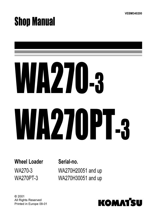
Shop Manual VEBM340200
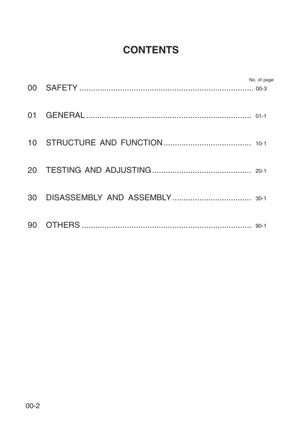
– Contents
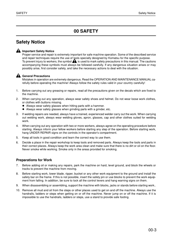
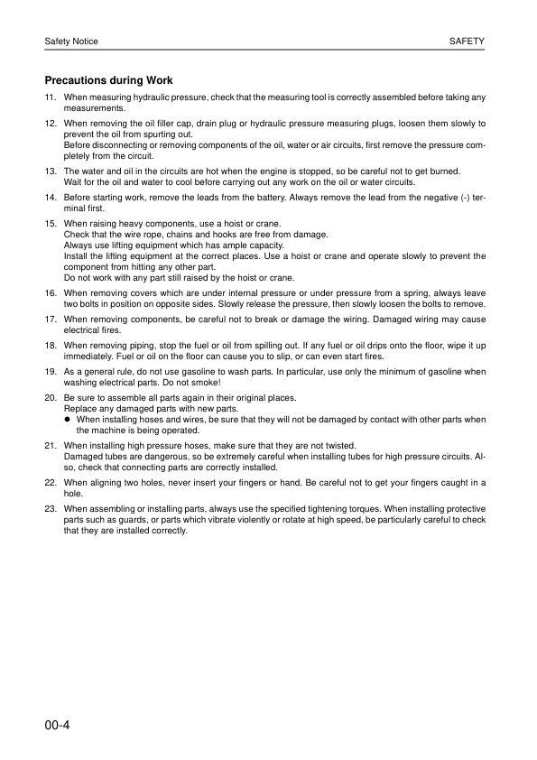
– Safety notice
– Foreword
– How to read the shop manual
– Hoisting instructions
01 General
– WA270-3: Dimensions, Operating Data
– WA270PT-3: Dimensions, Operating Data
– Specifications
– WA270-3: Weight Table
– WA270PT-3: Weight Table
– Lubricants and Operating Equipment
– Maintenance Schedule
– Outlines of Service
– Torque List
– General View of Controls and Gauges
– Emergency Drive
10 Structure and Function
– Power Train
– Power Train System
– Torque Converter and Gearbox Piping
– Torque Converter
— Principle of Operation
– Powershift Transmission
— Reversing Transmission 4WG-150
— Front View
— Side View
— Rear View
— Electro Hydraulic Control Valve
—- Detail ‘X’
— Inductive Sender
— Proximity Switch
— Pressure Check Points
— Transmission Hydraulic Diagram
— Solenoid Expansion Valve and Overlap Valve
— Thermostat Valve
— Reversing Transmission 4WG-160
— Front View
— Side View
— Rear View
— Electro-Hydraulic Shift Control with Proportional Valves
— Measuring Points and Conenctions
— Oil Circuit Diagram – Forward 1. Speed
— Inductive Sender
— Proximity Switch
— Thermostat Valve
– Drive Shaft
– Front and Rear Axles
– Differential Unit CK
– Differential
— Limited Slip Differential
– Wheel Hub
– Axle Mounting
– Steering Articulation Joint
— Outline
— Assembly
– Steering System
— Steering Column, Orbit Roll
— Steering Hydraukic Diagram
— Hydraulic Steering System
— In Neutral
— In Use
— Steering Servostat Control Valve
— Neutral Position
— Steering Position
— Steering and Working Hydraulic Pump
— Steering Orbit Roll
— Steering Valve Block
— Steering Damper
– Steering Cylinder
— Steering Cylinder
– Emergency Steering Pump
– Brake System
— Brake Valve
— Operating
— Brake System Circuit
— Gear Pump
— Pressure Filter
— Pressure Regulating Valve
— Operation
— Pressure Switch
— Brake Accumulator
— Hydraulic Circuit
— Main Brake
— Outline
— Operation
— Parking Brake
— 4WG-150
— 4WG-160
– Work Equipment Hydraulic System
— Pilot Servo System
— Oil Cooler
— Combined Cooler
— Working Hydraulic Pump
— WA270-3: Hydraulic System Diagram
— WA270PT-3: Hydraulic System Diagram
— WA270-3: Cut Off Valve
— WA270PT-3: Pilot Solenoid Valve
— Main Control Valve
— Shock and Anticavitation Valve
— Anticavitation Valve
— Pressure Control Valve
— Joystick, Servo Control Valve
— Lift Cylinder
— Tilt Cylinder
— ALS-Control Unit
— ALS Hydraulic Diagram
— GasSide Test
— Topping Up Gas Pressure
— Hydraulic Accumulator
– Lifting Frame
— WA270-3
— WA270PT-3
– Bucket Positioner and Boom Kick Out
— WA270-3
— WA270PT-3
— Bucket or Fork Positioner
— Boom Kick Out
– Machine Monitor System
— Main Monitor
— Display Function
— Switch Function
— Maintenance Monitor
— Display Function
– Electrical System
— Pre-Heater Plug
— Fuses
— Slow Blow Fuses
— Relays
— Heating and Ventilation System
— Wiring Diagrams
– Air Conditioner
— In General
— Characteristics
— Physical Datas
— Function
— Coolant Circuit
— Condenser
— Vaporiser
— Filter/Dryer
— Description
— Design
— Installation
— Safety
— Handling Coolants
— First Aid
— Operation
— Switch-On
— Maintenance
— Timetable
— Instructions
— Regular Maintenance
— Filling
— Evacuation
— Siphoning Coolant
— Filling Quantity
— Checking Coolant Level
— Compressor Oil Change
— Exchange of Magnetic Clutch
— Exchange of Compressor
— Service Operations
— Electrical System
— Pin assignment
— Wiring Diagram
— Technical Data
— Fault Diagnosis
— Preconditions
— Fan
— Operating Mode Switch
— Circulating Air Mode
— Temperature Setting
— Air Conditioning Mode
— Troubleshooting
20 Testing and Adjusting
– Contents
— Standard Value Table
— WA270-3
—- Engine
—- Chassis
— WA270PT-3
—- Engine
—- Chassis
— Test Certificate
— WA270-3, current
— WA270PT-3, current
— WA270-3, new
— WA270PT-3, new
— Engine RPM Load
— Hydraulic RPM Load
— Torque Converter And Transmission Pressure
— Current, with 4WG-150
— New, with 4WG-160
— Inductive Sender
— Proximity Switch
— Operating Force and Travel of Speed Lever
— Operating Force of Steering Wheel
— Operating Time for Steering Wheel
— Steering Pressure
— Switch Pump Pressure Cut-Off
— Working Hydraulic Pressure
— Servo Pilot Pressure
— Hydraulic Drift of Work Equipment
— Work Equipment
— Brake Oil Pressure
— Brake Wear
— Bleeding of Brake
— Main Brake Performance
— Parking Brake Performance
— Main Monitor
— Speedometer Modul
— Boom Kick-Out
— Accelerator Pedal
– Troubleshooting
— Datas
— Connecting of AEB-Starter and ZF-Display
— Operating Instructions AEB-Starter
— 1 Introduction
— 2 List of abbreviations
— 3 Procedures to start AEB
— 4 Display
— Description of fault codes for ERGO-Control EST37
— 1 Introduction
— 2 Display during operation
— 3 Display during AEB-Mode
— 4 Definition of operating modes
— 5 Table of fault codes
— 6 Measuring of resistance at actuator/sensors and cable
30 Disassembly and Assembly
– Contents
— Method Of Using Manual
— Precautions
— Special Tool List
— Removal and Install
— Engine Hood
— Engine
— Radiator
— Fuel Tank
— Counterweight
— Hydraulic Tank
— Hydraulic Filter
— Steering Cylinder
— Bucket Cylinder
— Boom Cylinder
— Cab
— Main Monitor
— Maintenance Monitor
— PPCValve
— Main Control Valve
— Steering Valve
— Priority Valve
— Working and Steering Pump
— Drive Shaft
— Front Axle
— Rear Axle
— Center Hinge Pin
— ALS
— Air Conditioner
—- Condenser/Dry Receiver
—- Compressor
— Disassembly and Assembly
— Axle AP408
—- Overview
—- Gear Tooth-Contact
—- Braking System
—- Special Tools
—- Planetary Rigid Axle
—– 1. Final Drive
—— 1.1 Disassembly
—— 1.2 Assembly
——- 1.2.1 Hub Carrier
——– 1.2.1.1 Rolling Restistance of Wheel Bearing
——– 1.2.2 Hub
——– 1.2.3 Gear Ring Carrier
——— 1.2.3.1 Determine Disk Play
——— 1.2.3.2 Axial Play of Sun Gear
—– Check Tightness of Brake Hydraulic System
—– 2. Differential Carrier
—— 2.1 Disassembly
——- 2.1.1 Differential
——- 2.1.2 Drive Pinion
—— 2.2 Assembly
——- 2.2.1 Determine Thickness of Shim
——- 2.2.2 Rolling Resistance of Drive Pinion Bearing
——- 2.2.3 Differential
——– 2.2.3.1 Determine Disc Play
——– 2.2.3.2 Bearing Preload and Backlash
— Reversing Transmission 4WG-150
—- Special Tools
—- 1. Electro-Hydraulic Shifting Mechanism
—– 1.1 Disassembly
—– 1.2 Assembly
—— Oil Lines
—- 2. Gear Box
—– 2.1 Disassembly
—— 2.1.1 Converter Drive
—— 2.1.2.1.2 Filling and Switching Pressure Pumps
—— 2.1.3 Pressure Holding valve and PTO
—— 2.1.4 Removal of Multi-Disk Clutches and Countershaft
—— 2.1.5 Multi-Disk Clutches
—— 2.1.6 Output
—– 2.2 Assembly
—— 2.2.1 Transmission Housing
—— 2.2.2 Parking Brake
—— 2.2.3 Output
—— 2.2.4 Pre-Assembly Multi-Disk Clutches
—— 2.2.5 Determine Disk Clearance
—— 2.2.6 Pre-Assembly Multi-Disk Clutch Spur Gear K1
—— 2.2.7 Pre-Assembly KR/K2 Multi-Disk Clutches
—— 2.2.8 Pre-Assembly K4/K3 Multi-Disk Clutches
—— 2.2.9 Insert K3/K4 Clutches Into Housing
—— 2.2.10 Countershaft
—— 2.2.11 Install KV/K1 Into Housing
—— 2.2.12 Install Converter Pressure-Holding Valve
—— 2.2.13 Converter Filling and Switching Pump
—— 2.2.14 Engine Connection Housing
—— 2.2.15 PTO
—— 2.2.16 Mount Sealing Cap or Screw Plugs
—— 2.2.17 Mount Intake Manifold, Oil-Level Pipe, Filter and Ventilator
—— 2.2.18 Torque Converter
—— 2.2.19 Transmission General View
— Reversing Transmission 4WG-160
—- General View
—- Special Tools
—- 1. Hydraulic Control Unit
—– 1.1 Disassembly
—– 1.2 Assembly
—- 2. Powershift Transmission
—– 2.1 Disassembly
—— 2.1.1 Remove Filter Unit
—— 2.1.2 Separate Hydraulic Control Unit (HSG-94) and Duct Plate from Gearbox Housing
—— 2.1.3 Remove and Dismantel Converter Safety Valve
—— 2.1.4 Engine Connection-Converter
—— 2.1.5 Remove Transmission Pump
—— 2.1.6 Converter Pressure Valve
—— 2.1.7 Remount Output, Input and Clutches
—— 2.1.8 Dismantle Clutch KV and KR
—— 2.1.9 Dismantle Clutch K1, K2 and K3
—— 2.1.10 Dismantle Clutch K4
—— 2.1.11 Dismantle Input Shaft
—– 2.2 Assembly
—— 2.2.1 Mount Oil Pipes
—— 2.2.2 Assembly Clutch KV and KR
—— 2.2.3 Assembly Clutch K1, K2 and K3
—— 2.2.4 Assembly Cltch K4
—— 2.2.5 Pre-Assembly input Shaft
—— 2.2.6 Install Pre-Assembled Outputshaft and ´Clutches
—— 2.2.7 Output
—— 2.2.8 Converter Pressure Valve
—— 2.2.9 Oil Feed Housing-Transmission Pump
—— 2.2.10 Engine Connection-Converter
—— 2.2.11 Converter Safety Valve
—— 2.2.12 Fit Duct Plate
—— 2.2.13 Fit Hydraulic Control Unit
—— 2.2.14 Filter
—— 2.2.15 Speed Sensor and Inductive Transmitter
trouble1.pdf
– Connecting of AEB-Starter and ZF-Display:
– Operating Instructions AEB – Starter
– KOMATSU-P/N: 34Y-00-H0P01
— Introduction
— List of abbreviations
— Procedure to start AEB
—- D
—- Display
– Introduction
— Abbreviations
— ZF – Display (421-00-H0R05):
— Display during operation
— Display during AEB-Mode
– Definition of operating modes



Reviews
There are no reviews yet.