


Komatsu WA50-6 60001 & Up SEN04670-03 (Preview)
COVER
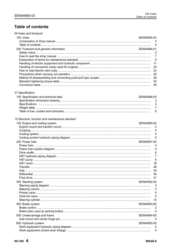
00 Index and foreword
100 Index
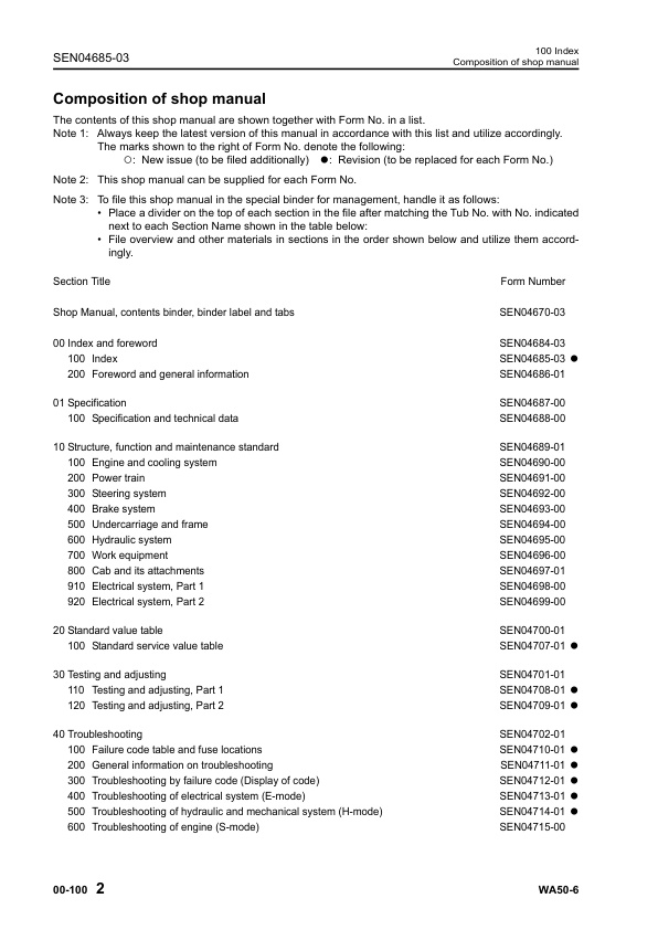
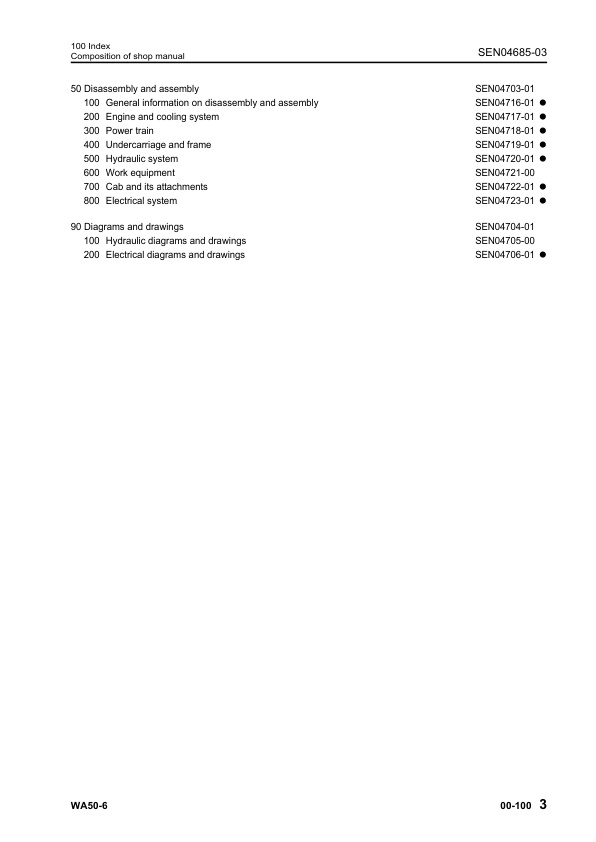
Composition of shop manual
Table of contents
200 Foreword and general information
Safety notice
How to read the shop manual
Explanation of terms for maintenance standard
Handling of electric equipment and hydraulic component
Handling of connectors newly used for engines
How to read electric wire code
Precautions when carrying out operation
Method of disassembling and connecting push-pull type coupler
Standard tightening torque table
Conversion table
01 Specification
100 Specification and technical data
Specification dimension drawing
Specifications
Weight table
Table of fuel, coolant and lubricants
10 Structure, function and maintenance standard
100 Engine and cooling system
Engine mount and transfer mount
Coupling
Cooling system
Cooling system hydraulic piping diagram
200 Power train
Power train
Power train system diagram
Drive shafts
HST hydraulic piping diagram
HST pump
HST motor
Transfer
Axle
Differential
Final drive
300 Steering system
Steering piping diagram
Steering column
Priority valve
Orbit-roll valve
Steering cylinder
400 Brake system
Brake control
Brake (also used as parking brake)
500 Undercarriage and frame
Axle mount and center hinge pin
600 Hydraulic system
Work equipment hydraulic piping diagram
Work equipment control lever linkage
Hydraulic tank
2-unit gear pump
Work equipment control valve
700 Work equipment
Work equipment linkage
Bucket
Bucket positioner
Work equipment cylinder
800 Cab and its attachments
Cab
Air conditioner
Heater
Canopy
910 Electrical system, Part 1
Machine monitor system
Machine monitor
HST electronic control system
Electrical system (HST controller system)
HST controller
920 Electrical system, Part 2
KOMTRAX system
Engine start circuit
Engine stop circuit
Preheating circuit
Travel mode selector switch
Travel speed control dial
Sensors
20 Standard value table
100 Standard service value table
Standard service value table for engine
Standard service value table for chassis
30 Testing and adjusting
110 Testing and adjusting, Part 1
Tools for testing, adjusting, and troubleshooting
Testing and adjusting engine speed
Testing exhaust gas color
Testing and adjusting valve clearance
Testing compression pressure
Testing engine oil pressure
Testing and adjusting fuel injection timing
Bleeding air from fuel circuit
Check of installed condition of cylinder head and manifolds
Check of engine piping for damage and looseness
Check of muffler and muffler stack for looseness and damage
Check of muffler function
Testing, adjusting and replacing alternator belt
Testing, adjusting and replacing air conditioner compressor belt
120 Testing and adjusting, Part 2
Testing operating force of accelerator pedal
Testing fuel level sensor
Testing directional lever
Testing and adjusting HST oil pressure
Adjusting travel speed sensor
Testing and adjusting steering wheel
Testing and adjusting steering oil pressure
Bleeding air from steering circuit
Testing brake pedal
Testing and adjusting brake pedal and linkage
Testing and adjusting brake switch
Testing brake performance
Testing brake disc wear
Testing and adjusting inching potentiometer linkage
Testing and adjusting parking brake control linkage
Measuring parking brake performance
Testing and adjusting work equipment control lever
Testing and adjusting work equipment hydraulic pressure
Testing travel of main control valve spool
Bleeding air from hydraulic circuit
Releasing remaining pressure in hydraulic circuit
Testing and adjusting bucket positioner
Checking proximity switch operation pilot lamp
Procedure for testing diodes
Preparation work for troubleshooting for electrical system
How to start operation of KOMTRAX terminal
Lamp display of KOMTRAX terminal
Removal and installation of KOMTRAX terminal
Pm clinic inspection chart
40 Troubleshooting
100 Failure code table and fuse locations
Failure codes table
How to select failure code display and how to read failure code
Fuse locations
200 General information on troubleshooting
Points to remember when troubleshooting
Sequence of events in troubleshooting
Testing before troubleshooting
Classification and procedures of troubleshooting
Information contained in troubleshooting table
Connection table for connector pin numbers
T- branch box and T- branch adapter table
300 Troubleshooting by failure code (Display of code)
Failure code [12] Directional (FNR) lever: Disconnection, ground fault, hot short
Failure code [13] Engine speed sensor: Disconnection, hot short
Failure code [14] Travel speed sensor: Disconnection, ground fault, hot short, defective installation
Failure code [22] MB (forward) pressure sensor: Disconnection, ground fault, hot short
Failure code [23] MA (reverse) pressure sensor: Disconnection, ground fault, hot short
Failure code [24] Travel speed variable potentiometer: Disconnection, ground fault, hot short
Failure code [25] Inching pedal potentiometer: Disconnection, ground fault, hot short
Failure code [26] HST oil temperature sensor: Ground fault
Failure code [32] HST pump forward EPC: Disconnection, short circuit, ground fault, hot short
Failure code [33] HST pump reverse EPC: Disconnection, short circuit, ground fault, hot short
Failure code [34] HST motor EPC: Disconnection, short circuit, ground fault, hot short
Failure code [36] HST pump forward EPC/reverse EPC: Sticking (foreign matter in system etc.)
Failure code [42] HST oil temperature: Overheat
Failure code [52] Source voltage: Voltage drop, disconnection
Failure code [53] Solenoid power supply: Voltage drop, disconnection
Failure code [54] ACC signal: Disconnection, ground fault
Failure code [55] Potentiometer power supply: Ground fault, hot short
400 Troubleshooting of electrical system (E-mode)
E-1 Engine does not start
E-2 Engine does not stop
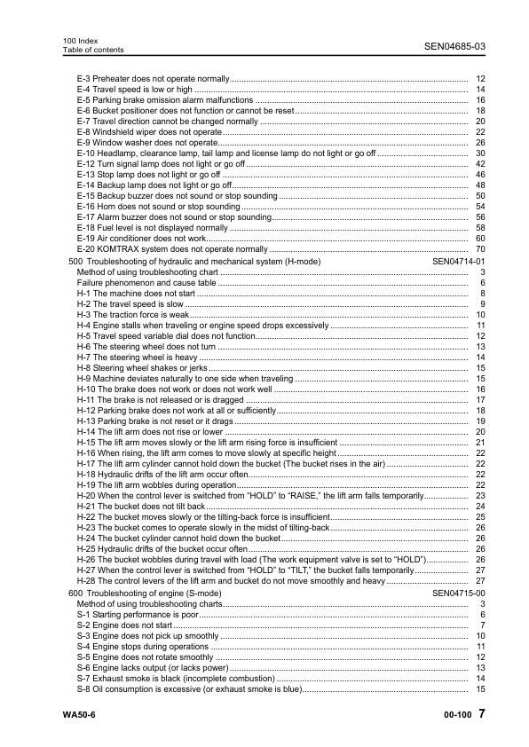
E-3 Preheater does not operate normally
E-4 Travel speed is low or high
E-5 Parking brake omission alarm malfunctions
E-6 Bucket positioner does not function or cannot be reset
E-7 Travel direction cannot be changed normally
E-8 Windshield wiper does not operate
E-9 Window washer does not operate
E-10 Headlamp, clearance lamp, tail lamp and license lamp do not light or go off
E-11 Working lamp and rotary lamp do not light or go off
E-12 Turn signal lamp does not light or go off
E-13 Stop lamp does not light or go off
E-14 Backup lamp does not light or go off
E-15 Backup buzzer does not sound or stop sounding
E-16 Horn does not sound or stop sounding
E-17 Alarm buzzer does not sound or stop sounding
E-18 Fuel level is not displayed normally
E-19 Air conditioner does not work
E-20 KOMTRAX system does not operate normally
500 Troubleshooting of hydraulic and mechanical system (H-mode)
Method of using troubleshooting chart
Failure phenomenon and cause table
H-1 The machine does not start
H-2 The travel speed is slow
H-3 The traction force is weak
H-4 Engine stalls when traveling or engine speed drops excessively
H-5 Travel speed variable dial does not function
H-6 The steering wheel does not turn
H-7 The steering wheel is heavy
H-8 Steering wheel shakes or jerks
H-9 Machine deviates naturally to one side when traveling
H-10 The brake does not work or does not work well
H-11 The brake is not released or is dragged
H-12 Parking brake does not work at all or sufficiently
H-13 Parking brake is not reset or it drags
H-14 The lift arm does not rise or lower
H-15 The lift arm moves slowly or the lift arm rising force is insufficient
H-16 When rising, the lift arm comes to move slowly at specific height
H-17 The lift arm cylinder cannot hold down the bucket (The bucket rises in the air)
H-18 Hydraulic drifts of the lift arm occur often
H-19 The lift arm wobbles during operation
H-20 When the control lever is switched from “HOLD” to “RAISE,” the lift arm falls temporarily
H-21 The bucket does not tilt back
H-22 The bucket moves slowly or the tilting-back force is insufficient
H-23 The bucket comes to operate slowly in the midst of tilting-back
H-24 The bucket cylinder cannot hold down the bucket
H-25 Hydraulic drifts of the bucket occur often
H-26 The bucket wobbles during travel with load (The work equipment valve is set to “HOLD”)
H-27 When the control lever is switched from “HOLD” to “TILT,” the bucket falls temporarily
H-28 The control levers of the lift arm and bucket do not move smoothly and heavy
600 Troubleshooting of engine (S-mode)
Method of using troubleshooting charts
S-1 Starting performance is poor
S-2 Engine does not start
S-3 Engine does not pick up smoothly
S-4 Engine stops during operations
S-5 Engine does not rotate smoothly
S-6 Engine lacks output (or lacks power)
S-7 Exhaust smoke is black (incomplete combustion)
S-8 Oil consumption is excessive (or exhaust smoke is blue)
S-9 Oil becomes contaminated quickly
S-10 Fuel consumption is excessive
S-11 Oil is in coolant (or coolant spurts back or coolant level goes down)
S-12 Oil pressure drops
S-13 Oil level rises (Entry of coolant/fuel)
S-14 Coolant temperature becomes too high (overheating)
S-15 Abnormal noise is made
S-16 Vibration is excessive
50 Disassembly and assembly
100 General information on disassembly and assembly
How to read this manual
Coating materials list
Special tools list
200 Engine and cooling system
Removal and installation of fuel injection pump assembly
Removal and installation of nozzle holder assembly
Removal and installation of cylinder head assembly
Removal and installation of radiator assembly
Removal and installation of engine hood assembly
Removal and installation of hydraulic oil cooler assembly
Removal and installation of radiator and hydraulic oil cooler assembly
Removal and installation of engine and HST pump assembly
Removal and installation of engine front oil seal assembly
Removal and installation of engine rear oil seal assembly
Removal and installation of fuel tank assembly
300 Power train
Removal and installation of transfer assembly
Disassembly and assembly of transfer assembly
Removal and installation of parking brake assembly
Disassembly and assembly of parking brake assembly
Removal and installation of front axle assembly
Removal and installation of rear axle assembly
Disassembly and assembly of axle housing assembly
Disassembly and assembly of differential assembly
400 Undercarriage and frame
Removal and installation of center hinge pin
Removal and installation of counterweight assembly
500 Hydraulic system
Removal and installation of HST pump assembly
Removal and installation of HST motor assembly
Removal and installation of work equipment control valve assembly
Removal and installation of hydraulic tank assembly
Disassembly and assembly of hydraulic cylinder assembly
600 Work equipment
Removal and installation of work equipment assembly
700 Cab and its attachments
Removal and installation of canopy assembly
Removal and installation of operator’s cab assembly
Removal and installation of operator’s cab glass (Stuck glass)
Removal and installation of floor frame assembly
Removal and installation of heater unit assembly
Removal and installation of air conditioner unit assembly
Removal and installation of air conditioner condenser assembly
Removal and installation of air conditioner compressor assembly
800 Electrical system
Removal and installation of font monitor panel assembly
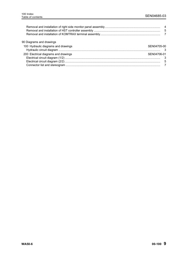
Removal and installation of right side monitor panel assembly
Removal and installation of HST controller assembly
Removal and installation of KOMTRAX terminal assembly
90 Diagrams and drawings
100 Hydraulic diagrams and drawings
Hydraulic circuit diagram
200 Electrical diagrams and drawings
Electrical circuit diagram (1/2)
Electrical circuit diagram (2/2)
Connector list and stereogram


Reviews
There are no reviews yet.