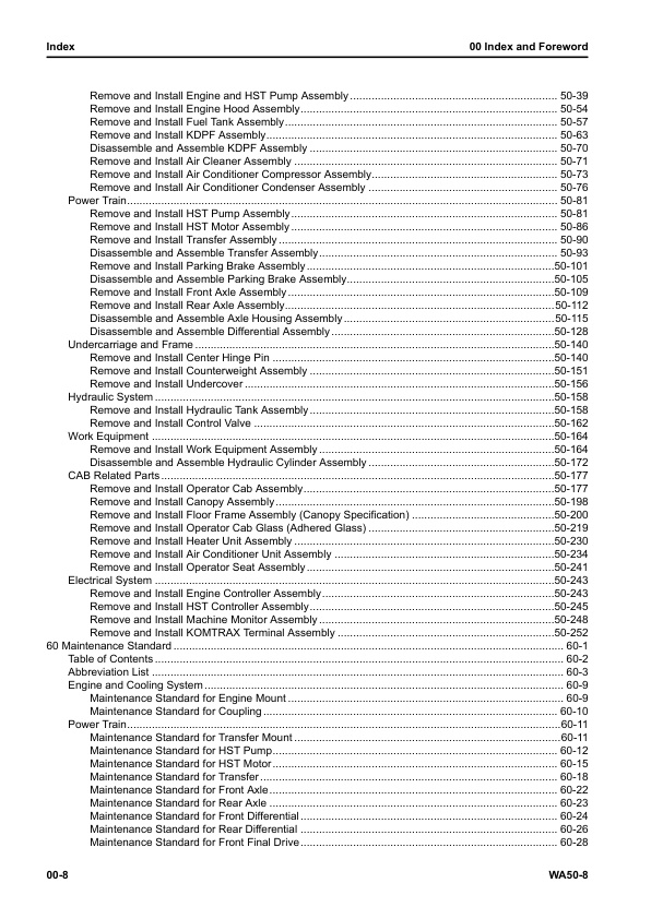
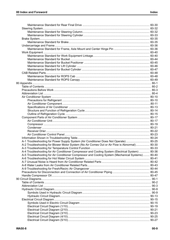
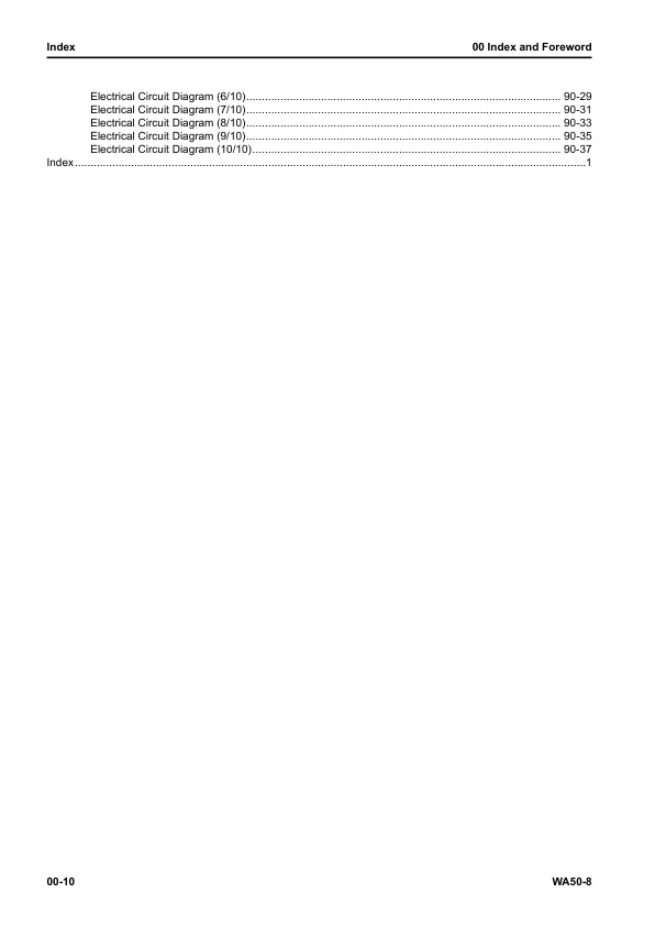
Komatsu WA50-8 83001 & Up SEN07007-01 (Preview)
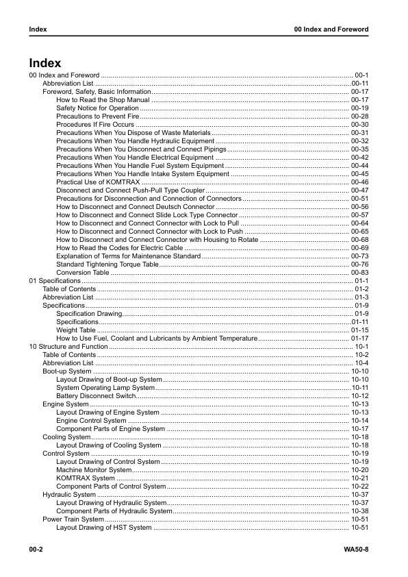
00 Index and Foreword
– Index
– Abbreviation List
– Foreword, Safety, Basic Information
— How to Read the Shop Manual
— Safety Notice for Operation
— Precautions to Prevent Fire
— Procedures If Fire Occurs
— Precautions When You Dispose of Waste Materials
— Precautions When You Handle Hydraulic Equipment
— Precautions When You Disconnect and Connect Pipings
— Precautions When You Handle Electrical Equipment
— Precautions When You Handle Fuel System Equipment
— Precautions When You Handle Intake System Equipment
— Practical Use of KOMTRAX
— Disconnect and Connect Push-Pull Type Coupler
— How to Disconnect and Connect Type 1 Push-Pull Type Coupler
— How to Disconnect and Connect Type 2 Push-Pull Type Coupler
— How to Disconnect and Connect Type 3 Push-Pull Type Coupler
— Precautions for Disconnection and Connection of Connectors
— How to Disconnect and Connect Deutsch Connector
— How to Disconnect and Connect Slide Lock Type Connector
— How to Disconnect and Connect Connector with Lock to Pull
— How to Disconnect and Connect Connector with Lock to Push
— How to Disconnect and Connect Connector with Housing to Rotate
— How to Read the Codes for Electric Cable
— Explanation of Terms for Maintenance Standard
— Standard Tightening Torque Table
— Conversion Table
01 Specifications
– Table of Contents
– Abbreviation List
– Specifications
— Specification Drawing
— Specification Drawing: WA50-8
— Specifications
— Specifications: WA50-8
— Weight Table
— Weight Table: WA50-8
— How to Use Fuel, Coolant and Lubricants by Ambient Temperature
10 Structure and Function
– Table of Contents
– Abbreviation List
– Boot-up System
— Layout Drawing of Boot-up System
— System Operating Lamp System
— System Diagram of System Operating Lamp System
— Function of Operation Lamp System
— Battery Disconnect Switch
— Function of Battery Disconnect Switch
– Engine System
— Layout Drawing of Engine System
— Engine Control System
— System Diagram of Engine Control
— Function of Engine Control System
— Component Parts of Engine System
— Coupling
– Cooling System
— Layout Drawing of Cooling System
— Specifications of Cooling System
– Control System
— Layout Drawing of Control System
— Machine Monitor System
— System Diagram of Machine Monitor System
— KOMTRAX System
— System Diagram of KOMTRAX System
— Function of KOMTRAX System
— Component Parts of Control System
— Machine Monitor
— KOMTRAX Terminal
— HST Controller
– Hydraulic System
— Layout Drawing of Hydraulic System
— Component Parts of Hydraulic System
— Hydraulic Tank
— Steering and Work Equipment Pump
— Control Valve
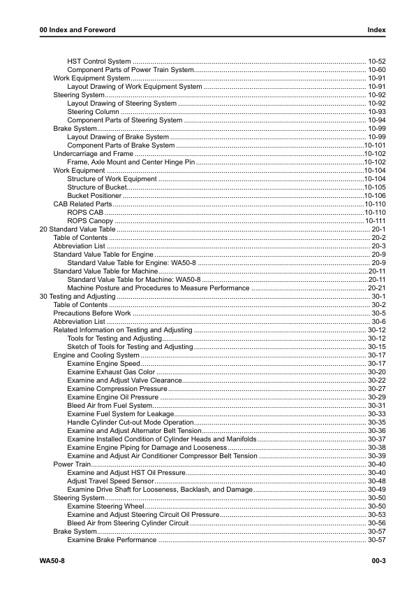
– Power Train System
— Layout Drawing of HST System
— HST Control System
— System Diagram of HST Control System
— Travel Speed Adjustment Function
— Traction Control Function
— Machine Protection Function by HST Controller
— Component Parts of Power Train System
— Drive Shaft
— HST Pump
— HST Motor
— Transfer
— Axle
— Differential
— Final Drive
– Work Equipment System
— Layout Drawing of Work Equipment System
– Steering System
— Layout Drawing of Steering System
— Steering Column
— Structure of Steering Column
— Component Parts of Steering System
— Priority Valve
— Orbitrol Valve
– Brake System
— Layout Drawing of Brake System
— Component Parts of Brake System
— Brake
– Undercarriage and Frame
— Frame, Axle Mount and Center Hinge Pin
— Structure of Frame, Axle Mount and Center Hinge Pin
— Function of Frame, Axle Mount and Center Hinge Pin
– Work Equipment
— Structure of Work Equipment
— Structure of Bucket
— Bucket Positioner
— Structure of Bucket Positioner
— Function of Bucket Positioner
— Operation of Bucket Positioner
– CAB Related Parts
— ROPS CAB
— Structure of ROPS CAB
— Function of ROPS CAB
— ROPS Canopy
— Structure of ROPS Canopy
— Function of ROPS Canopy
20 Standard Value Table
– Table of Contents
– Abbreviation List
– Standard Value Table for Engine
— Standard Value Table for Engine: WA50-8
– Standard Value Table for Machine
— Standard Value Table for Machine: WA50-8
— Machine Posture and Procedures to Measure Performance
30 Testing and Adjusting
– Table of Contents
– Precautions Before Work
– Abbreviation List
– Related Information on Testing and Adjusting
— Tools for Testing and Adjusting
— Sketch of Tools for Testing and Adjusting
– Engine and Cooling System
— Examine Engine Speed
— How to Examine Engine Speed
— Examine Exhaust Gas Color
— How to Examine Exhaust Gas Color with Handy Smoke Checker
— How to Examine Exhaust Gas Color with Smoke Meter
— Examine and Adjust Valve Clearance
— How to Examine Valve Clearance
— How to Adjust Valve Clearance
— Examine Compression Pressure
— How to Examine Compression Pressure
— Examine Engine Oil Pressure
— How to Examine Engine Oil Pressure
— Bleed Air from Fuel System
— How to Bleed Air from Fuel System
— Examine Fuel System for Leakage
— How to Examine Fuel System for Leakage
— Handle Cylinder Cut-out Mode Operation
— Examine and Adjust Alternator Belt Tension
— How to Examine Alternator Belt Tension
— Adjust Alternator Belt Tension
— Examine Installed Condition of Cylinder Heads and Manifolds
— How to Examine Installed Condition of Cylinder Heads and Manifolds
— Examine Engine Piping for Damage and Looseness
— How to Examine Engine Piping for Damage and Looseness
— Examine and Adjust Air Conditioner Compressor Belt Tension
— How to Examine Air Conditioner Compressor Belt Tension
— How to Adjust Air Conditioner Compressor Belt Tension
– Power Train
— Examine and Adjust HST Oil Pressure
— How to Examine HST Oil Pressure
— How to Adjust HST Oil Pressure
— Adjust Travel Speed Sensor
— How to Adjust Travel Speed Sensor
— Examine Drive Shaft for Looseness, Backlash, and Damage
— How to Examine Drive Shaft for Looseness, Backlash, and Damage
– Steering System
— Examine Steering Wheel
— How to Examine Steering Wheel
— Examine and Adjust Steering Circuit Oil Pressure
— How to Examine Steering Circuit Oil Pressure
— How to Adjust Steering Circuit Oil Pressure
— Bleed Air from Steering Cylinder Circuit
— How to Bleed Air from Steering Cylinder Circuit
– Brake System
— Examine Brake Performance
— How to Examine Brake Performance
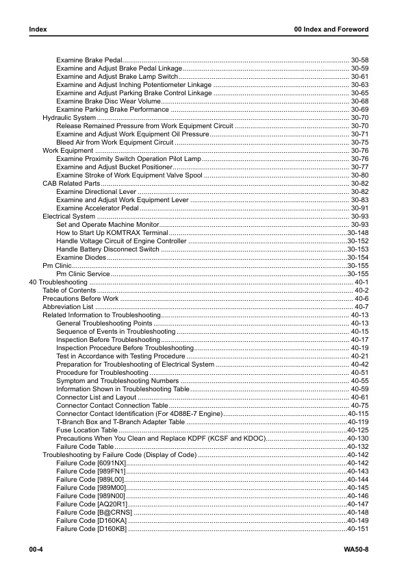
— Examine Brake Pedal
— How to Examine Brake Pedal
— Examine and Adjust Brake Pedal Linkage
— How to Examine Brake Pedal Linkage
— How to Adjust Brake Pedal Linkage
— Examine and Adjust Brake Lamp Switch
— How to Examine Brake Lamp Switch
— How to Adjust Brake Lamp Switch
— Examine and Adjust Inching Potentiometer Linkage
— How to Examine Inching Potentiometer Linkage
— How to Adjust Inching Potentiometer Linkage
— Examine and Adjust Parking Brake Control Linkage
— How to Examine Parking Brake Control Linkage
— How to Adjust Brake Parking Brake Control Linkage
— Examine Brake Disc Wear Volume
— How to Examine Brake Disc Wear Volume
— Examine Parking Brake Performance
— How to Examine Parking Brake Performance
– Hydraulic System
— Release Remained Pressure from Work Equipment Circuit
— How to Release Remained Pressure from Work Equipment Circuit
— Examine and Adjust Work Equipment Oil Pressure
— How to Examine Work Equipment Oil Pressure
— How to Adjust Work Equipment Oil Pressure
— Bleed Air from Work Equipment Circuit
— How to Bleed Air from Work Equipment Circuit
– Work Equipment
— Examine Proximity Switch Operation Pilot Lamp
— How to Examine Proximity Switch Operation Pilot Lamp
— Examine and Adjust Bucket Positioner
— How to Examine Bucket Positioner
— How to Adjust Bucket Positioner
— Examine Stroke of Work Equipment Valve Spool
— How to Examine Stroke of Work Equipment Valve Spool
– CAB Related Parts
— Examine Directional Lever
— How to Examine Directional Lever
— Examine and Adjust Work Equipment Lever
— How to Examine Work Equipment Control Lever
— How to Adjust Work Equipment Control Lever
— Examine Accelerator Pedal
— How to Examine Accelerator Pedal
– Electrical System
— Set and Operate Machine Monitor
— Operator Mode
— Examine Function by LCD (Liquid Crystal Display)
— Examine Function of Service Meter
— Usage Limitation and Maintenance Password Change Function(When Password Length is 10)
— Usage Limitation and Maintenance Password Change Function(When Password Length is 6)
— Service Mode
— How to Operate Service Mode
— How to See Pre-defined Monitoring Information
— How to Examine Self-Define Monitor Information
— Abnormality Record Menu
— How to Reset Maintenance Time
— How to See Maintenance Record
— How to Operate Maintenance Mode Setting
— How to Set Phone Number Entry
— Default Menu
— Diagnostic Tests Menu
— Adjustment Menu
— KOMTRAX Settings Menu
— How to Show Service Message
— How to Start Up KOMTRAX Terminal
— Handle Voltage Circuit of Engine Controller
— Handle Battery Disconnect Switch
— Examine Diodes
— How to Examine Diodes by Digital Tester
— How to Examine Diodes by Analog Tester
– Pm Clinic
— Pm Clinic Service
— Pm Clinic Check Sheet: WA50-8
40 Troubleshooting
– Table of Contents
– Precautions Before Work
– Abbreviation List
– Related Information to Troubleshooting
— General Troubleshooting Points
— Sequence of Events in Troubleshooting
— Inspection Before Troubleshooting
— Inspection Procedure Before Troubleshooting
— Walk-around Check
— Test in Accordance with Testing Procedure
— Examine Fuel Level and Type
— Examine for Impure Ingredient in Fuel
— Examine Feed Pump Prefilter
— Examine Fuel Prefilter
— Examine Water Separator, Drain Water and Sediment
— Examine Fuel Main Filter
— Examine Engine Oil Level (Oil Quantity in Oil Pan) and Type
— Examine Coolant Level (Reservoir Tank)
— Examine Air Cleaner Clogging
— Clean Outer Element
— Replace Element
— Examine Hydraulic Oil Level
— Examine Hydraulic Oil Filter
— Examine the Oil Level in the Transfer Case
— Examine Oil Level in Front Axle Case
— Examine Oil Level in Rear Axle Case
— Bleed Air from Fuel System
— Bleed Air from Hydraulic System
— How to Examine Electrical Components
— Preparation for Troubleshooting of Electrical System
— Preparation for Troubleshooting of Machine Monitor
— Preparation for Troubleshooting of Engine Controller
— Preparation for Troubleshooting of HST Controller
— Preparation for Troubleshooting of KOMTRAX Terminal
— How to Disconnect and Connect Connector with a Special Lock
— Procedure for Troubleshooting
— Symptom and Troubleshooting Numbers
— Information Shown in Troubleshooting Table
— Connector List and Layout
— Connector Contact Connection Table
— Connector Contact Identification (For 4D88E-7 Engine)
— T-Branch Box and T-Branch Adapter Table
— Fuse Location Table
— Precautions When You Clean and Replace KDPF (KCSF and KDOC)
— Failure Code Table
– Troubleshooting by Failure Code (Display of Code)
— Failure Code [6091NX]
— Failure Code [989FN1]
— Failure Code [989L00]
— Failure Code [989M00]
— Failure Code [989N00]
— Failure Code [AQ20R1]
— Failure Code [B@CRNS]
— Failure Code [D160KA]
— Failure Code [D160KB]
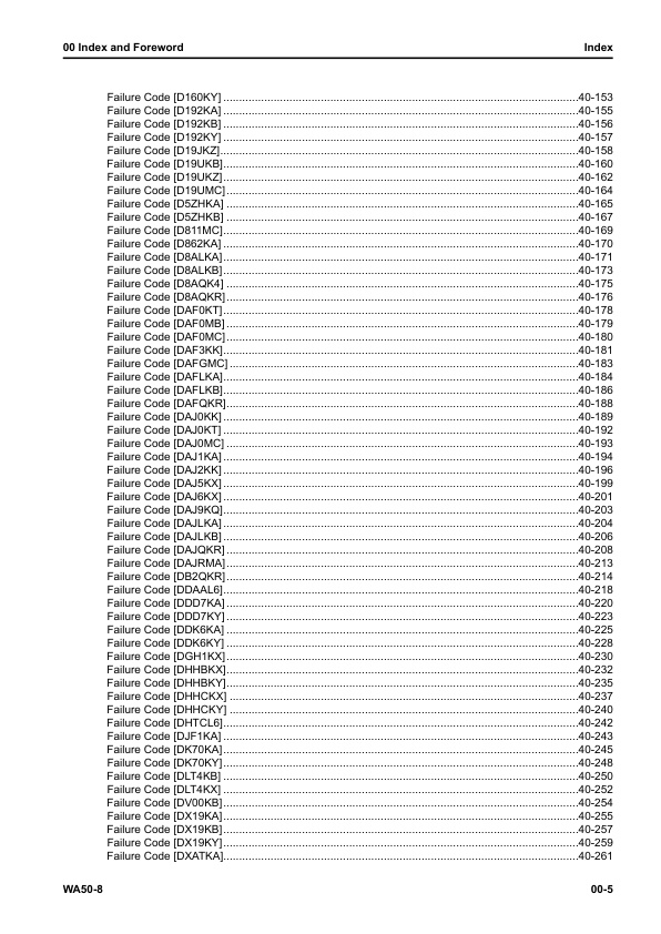
— Failure Code [D160KY]
— Failure Code [D192KA]
— Failure Code [D192KB]
— Failure Code [D192KY]
— Failure Code [D19JKZ]
— Failure Code [D19UKB]
— Failure Code [D19UKZ]
— Failure Code [D19UMC]
— Failure Code [D5ZHKA]
— Failure Code [D5ZHKB]
— Failure Code [D811MC]
— Failure Code [D862KA]
— Failure Code [D8ALKA]
— Failure Code [D8ALKB]
— Failure Code [D8AQK4]
— Failure Code [D8AQKR]
— Failure Code [DAF0KT]
— Failure Code [DAF0MB]
— Failure Code [DAF0MC]
— Failure Code [DAF3KK]
— Failure Code [DAFGMC]
— Failure Code [DAFLKA]
— Failure Code [DAFLKB]
— Failure Code [DAFQKR]
— Failure Code [DAJ0KK]
— Failure Code [DAJ0KT]
— Failure Code [DAJ0MC]
— Failure Code [DAJ1KA]
— Failure Code [DAJ2KK]
— Failure Code [DAJ5KX]
— Failure Code [DAJ6KX]
— Failure Code [DAJ9KQ]
— Failure Code [DAJLKA]
— Failure Code [DAJLKB]
— Failure Code [DAJQKR]
— Failure Code [DAJRMA]
— Failure Code [DB2QKR]
— Failure Code [DDAAL6]
— Failure Code [DDD7KA]
— Failure Code [DDD7KY]
— Failure Code [DDK6KA]
— Failure Code [DDK6KY]
— Failure Code [DGH1KX]
— Failure Code [DHHBKX]
— Failure Code [DHHBKY]
— Failure Code [DHHCKX]
— Failure Code [DHHCKY]
— Failure Code [DHTCL6]
— Failure Code [DJF1KA]
— Failure Code [DK70KA]
— Failure Code [DK70KY]
— Failure Code [DLT4KB]
— Failure Code [DLT4KX]
— Failure Code [DV00KB]
— Failure Code [DX19KA]
— Failure Code [DX19KB]
— Failure Code [DX19KY]
— Failure Code [DXATKA]
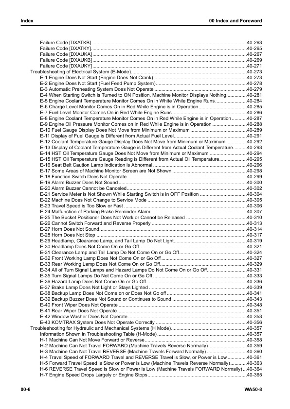
— Failure Code [DXATKB]
— Failure Code [DXATKY]
— Failure Code [DXAUKA]
— Failure Code [DXAUKB]
— Failure Code [DXAUKY]
– Troubleshooting of Electrical System (E-Mode)
— E-1 Engine Does Not Start (Engine Does Not Crank)
— E-2 Engine Does Not Start (Fuel Feed Pump System)
— E-3 Automatic Preheating System Does Not Operate
— E-4 When Starting Switch is Turned to ON Position, Machine Monitor Displays Nothing
— E-5 Engine Coolant Temperature Monitor Comes On in White While Engine Runs
— E-6 Charge Level Monitor Comes On in Red While Engine is in Operation
— E-7 Fuel Level Monitor Comes On in Red While Engine Runs
— E-8 Engine Coolant Temperature Monitor Comes On in Red While Engine is in Operation
— E-9 Engine Oil Pressure Monitor Comes on in Red While Engine is in Operation
— E-10 Fuel Gauge Display Does Not Move from Minimum or Maximum
— E-11 Display of Fuel Gauge is Different from Actual Fuel Level
— E-12 Coolant Temperature Gauge Display Does Not Move from Minimum or Maximum
— E-13 Display of Coolant Temperature Gauge is Different from Actual Coolant Temperature
— E-14 HST Oil Temperature Gauge Does Not Move from Minimum or Maximum
— E-15 HST Oil Temperature Gauge Reading is Different from Actual Oil Temperature
— E-16 Seat Belt Caution Lamp Indication is Abnormal
— E-17 Some Areas of Machine Monitor Screen are Not Shown
— E-18 Function Switch Does Not Operate
— E-19 Alarm Buzzer Does Not Sound
— E-20 Alarm Buzzer Cannot be Canceled
— E-21 Service Meter is Not Shown While Starting Switch is in OFF Position
— E-22 Machine Does Not Change to Service Mode
— E-23 Travel Speed is Too Slow or Fast
— E-24 Malfunction of Parking Brake Reminder Alarm
— E-25 The Bucket Positioner Does Not Work or Cannot be Released
— E-26 Cannot Switch Forward and Reverse Properly
— E-27 Horn Does Not Sound
— E-28 Horn Does Not Stop
— E-29 Headlamp, Clearance Lamp, and Tail Lamp Do Not Light
— E-30 Headlamp Does Not Come On or Go Off
— E-31 Clearance Lamp and Tail Lamp Do Not Come On or Go Off
— E-32 Front Working Lamp Does Not Come On or Go Off
— E-33 Rear Working Lamp Does Not Come On or Go Off
— E-34 All of Turn Signal Lamps and Hazard Lamps Do Not Come On or Go Off
— E-35 Turn Signal Lamps Do Not Come On or Go Off
— E-36 Hazard Lamp Does Not Come On or Go Off
— E-37 Brake Lamp Does Not Light or Stays Lighted
— E-38 Backup Lamp Does Not Come on or Does Not Go off
— E-39 Backup Buzzer Does Not Sound or Continues to Sound
— E-40 Front Wiper Does Not Operate
— E-41 Rear Wiper Does Not Operate
— E-42 Window Washer Does Not Operate
— E-43 KOMTRAX System Does Not Operate Correctly
– Troubleshooting for Hydraulic and Mechanical Systems (H Mode)
— Information Shown in Troubleshooting Table (H-Mode)
— H-1 Machine Can Not Move Forward or Reverse
— H-2 Machine Can Not Travel FORWARD (Machine Travels Reverse Normally)
— H-3 Machine Can Not Travel REVERSE (Machine Travels Forward Normally)
— H-4 Travel Speed of FORWARD Travel and REVERSE Travel is Slow, or Power is Low
— H-5 Forward Travel Speed is Slow or Power is Low (Machine Travels Reverse Normally)
— H-6 REVERSE Travel Speed is Slow or Power is Low (Machine Travels FORWARD Normally)
— H-7 Engine Speed Drops Largely or Engine Stops
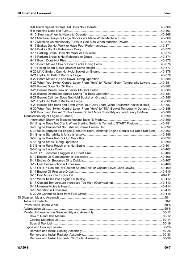
— H-8 Travel Speed Control Dial Does Not Operate
— H-9 Machine Does Not Turn
— H-10 Steering Wheel is Heavy to Operate
— H-11 Machine Sways or Large Shocks are Made While Machine Turns
— H-12 Machine Unintentionally Turns to One Side When Machine Travels
— H-13 Brakes Do Not Work or Have Poor Performance
— H-14 Brakes Do Not Release or Drag
— H-15 Parking Brake Does Not Work or It is Weak
— H-16 Parking Brake is Not Released or Drags
— H-17 Boom Does Not Rise
— H-18 Boom Moves Slow or Boom Lacks Lifting Force
— H-19 Rising Boom Slows Down at Some Height
— H-20 Lift Cylinders Can Not Hold Bucket on Ground
— H-21 Hydraulic Drift of Boom is Large
— H-22 Boom Moves Up and Down During Operation
— H-23 When You Switch Control Lever From “Hold” to “Raise”, Boom Temporarily Lowers
— H-24 Bucket Does Not Tilt Back
— H-25 Bucket Moves Slow or Lacks Tilt-Back Force
— H-26 Bucket Decreases Speed During Tilt-Back Operation
— H-27 Bucket Cylinder Does Not Hold Bucket on Ground
— H-28 Hydraulic Drift of Bucket is Large
— H-29 Bucket Tilts Back and Forth While You Carry Load (Work Equipment Valve in Hold)
— H-30 When You Switch Control Lever From “Hold” to “Tilt”, Bucket Temporarily Dumps
— H-31 Boom and Bucket Control Levers Do Not Move Smoothly and are Heavy to Move
– Troubleshooting of Engine (S-Mode)
— Information Shown in Troubleshooting Table (S-Mode)
— S-1 Engine Does Not Crank When Starting Switch is Turned to START Position
— S-2 Engine Cranks but No Exhaust Smoke Comes Out
— S-3 Fuel is Sprayed but Engine Does Not Start (Misfiring: Engine Cranks but Does Not Start)
— S-4 Engine Startability is Unsatisfactory
— S-5 Engine Does Not Pick Up Smoothly
— S-6 Engine Stops During Operation
— S-7 Engine Runs Rough or is Not Stable
— S-8 Engine Lacks Power
— S-9 KDPF Becomes Clogged in a Short Time
— S-10 Engine Oil Consumption is Excessive
— S-11 Engine Oil Becomes Dirty Quickly
— S-12 Fuel Consumption is Excessive
— S-13 Oil is in Coolant (or Coolant Spurts Back or Coolant Level Goes Down)
— S-14 Engine Oil Pressure Drops
— S-15 Fuel Mixes into Engine Oil
— S-16 Water Mixes into Engine Oil (Milky)
— S-17 Coolant Temperature Increases Too High (Overheating)
— S-18 Unusual Noise is Heard
— S-19 Vibration is Excessive
— S-20 Air Cannot be Bled from Fuel Circuit
50 Disassembly and Assembly
– Table of Contents
– Precautions Before Work
– Abbreviation List
– Related Information on Disassembly and Assembly
— How to Read This Manual
— Coating Materials List
— Special Tool List
– Engine and Cooling System
— Remove and Install Cooling Assembly
— How to Remove Cooling Assembly
— How to Install Cooling Assembly
— Remove and Install Radiator Assembly
— How to Remove Radiator Assembly
— How to Install Radiator Assembly
— Remove and Install Hydraulic Oil Cooler Assembly
— How to Remove Hydraulic Oil Cooler Assembly
— How to Install Hydraulic Oil Cooler Assembly
— Remove and Install Engine and HST Pump Assembly
— Remove Engine and HST Pump Assembly
— Install Engine and HST Pump Assembly
— Remove and Install Engine Hood Assembly
— How to Remove Engine Hood Assembly
— How to Install Engine Hood Assembly
— Remove and Install Fuel Tank Assembly
— How to Remove Fuel Tank Assembly
— How to Install Fuel Tank Assembly
— Remove and Install KDPF Assembly
— How to Remove KDPF Assembly
— How to Install KDPF Assembly
— Disassemble and Assemble KDPF Assembly
— Remove and Install Air Cleaner Assembly
— How to Remove Air Cleaner Assembly
— How to Install Air Cleaner Assembly
— Remove and Install Air Conditioner Compressor Assembly
— How to Remove Air Conditioner Compressor Assembly
— How to Install Air Conditioner Compressor Assembly
— Remove and Install Air Conditioner Condenser Assembly
— How to Remove Air Conditioner Condenser Assembly
— How to Install Air Conditioner Condenser Assembly
– Power Train
— Remove and Install HST Pump Assembly
— Remove HST Pump Assembly
— Install HST Pump Assembly
— Remove and Install HST Motor Assembly
— How to Remove HST Motor Assembly
— How to Install HST Motor Assembly
— Remove and Install Transfer Assembly
— Remove Transfer Assembly
— Install Transfer Assembly
— Disassemble and Assemble Transfer Assembly
— Disassemble Transfer Assembly
— Assemble Transfer Assembly
— Remove and Install Parking Brake Assembly
— How to Remove Parking Brake Assembly
— Install Parking Brake Assembly
— Disassemble and Assemble Parking Brake Assembly
— Disassemble Parking Brake Assembly
— Assemble Parking Brake Assembly
— Remove and Install Front Axle Assembly
— How to Remove Front Axle Assembly
— How to Install Front Axle Assembly
— Remove and Install Rear Axle Assembly
— How to Remove Rear Axle Assembly
— How to Install Rear Axle Assembly
— Disassemble and Assemble Axle Housing Assembly
— How to Disassemble Axle Housing Assembly
— How to Assemble Axle Housing Assembly
— Disassemble and Assemble Differential Assembly
— How to Disassemble Differential Assembly
— How to Assemble Differential Assembly
– Undercarriage and Frame
— Remove and Install Center Hinge Pin
— How to Remove Center Hinge Pin
— How to Install Center Hinge Pin
— Remove and Install Counterweight Assembly
— How to Remove Counterweight Assembly
— How to Install Counterweight Assembly
— Remove and Install Undercover
— How to Remove Undercover
— How to Install Undercover
– Hydraulic System
— Remove and Install Hydraulic Tank Assembly
— How to Remove Hydraulic Tank Assembly
— How to Install Hydraulic Tank Assembly
— Remove and Install Control Valve
— How to Remove Control Valve
— How to Install Control Valve
– Work Equipment
— Remove and Install Work Equipment Assembly
— How to Remove Work Equipment Assembly
— How to Install Work Equipment Assembly
— Disassemble and Assemble Hydraulic Cylinder Assembly
— How to Disassemble Hydraulic Cylinder Assembly
— How to Assemble Hydraulic Cylinder Assembly
– CAB Related Parts
— Remove and Install Operator Cab Assembly
— How to Remove Operator Cab Assembly
— How to Install Operator Cab Assembly
— Remove and Install Canopy Assembly
— How to Remove Canopy Assembly
— How to Install Canopy Assembly
— Remove and Install Floor Frame Assembly (Canopy Specification)
— Remove Floor Frame Assembly (Canopy Specification)
— Install Floor Frame Assembly (Canopy Specification)
— Remove and Install Operator Cab Glass (Adhered Glass)
— How to Remove Operator Cab Glass (Adhered Glass)
— How to Install Operator Cab Glass (Adhered Glass)
— Remove and Install Heater Unit Assembly
— How to Remove Heater Unit Assembly
— How to Install Heater Unit Assembly
— Remove and Install Air Conditioner Unit Assembly
— How to Remove Air Conditioner Unit Assembly
— How to Install Air Conditioner Unit Assembly
— Remove and Install Operator Seat Assembly
— How to Remove Operator Seat Assembly
— How to Install Operator Seat Assembly
– Electrical System
— Remove and Install Engine Controller Assembly
— How to Remove Engine Controller Assembly
— How to Install Engine Controller Assembly
— Remove and Install HST Controller Assembly
— How to Remove HST Controller Assembly
— How to Install HST Controller Assembly
— Remove and Install Machine Monitor Assembly
— How to Remove Machine Monitor Assembly
— How to Install Machine Monitor Assembly
— Remove and Install KOMTRAX Terminal Assembly
— How to Remove KOMTRAX Terminal Assembly
— How to Install KOMTRAX Terminal Assembly
60 Maintenance Standard
– Table of Contents
– Abbreviation List
– Engine and Cooling System
— Maintenance Standard for Engine Mount
— Maintenance Standard for Coupling
– Power Train
— Maintenance Standard for Transfer Mount
— Maintenance Standard for HST Pump
— Maintenance Standard for HST Motor
— Maintenance Standard for Relief Valve of HST Motor
— Maintenance Standard for Transfer
— Maintenance Standard for Front Axle
— Maintenance Standard for Rear Axle
— Maintenance Standard for Front Differential
— Maintenance Standard for Rear Differential
— Maintenance Standard for Front Final Drive
— Maintenance Standard for Rear Final Drive
– Steering System
— Maintenance Standard for Steering Column
— Maintenance Standard for Steering Cylinder
– Brake System
— Maintenance Standard for Brake
– Undercarriage and Frame
— Maintenance Standard for Frame, Axle Mount and Center Hinge Pin
– Work Equipment
— Maintenance Standard for Work Equipment Linkage
— Maintenance Standard for Bucket
— Maintenance Standard for Bucket Positioner
— Maintenance Standard for Lift Cylinder
— Maintenance Standard for Bucket Cylinder
– CAB Related Parts
— Maintenance Standard for ROPS Cab
— Maintenance Standard for ROPS Canopy
80 Appendix
– Table of Contents
– Precautions Before Work
– Abbreviation List
– Air Conditioner System
— Precautions for Refrigerant
— Air Conditioner Component
— Specifications of Air Conditioner
— Structure and Function of Refrigeration Cycle
— Outline of Refrigeration Cycle
– Component Parts of Air Conditioner System
— Air Conditioner Unit
— Configuration Diagram of Air Conditioner Unit
— Compressor
— Structure of Compressor
— Specifications of Compressor
— Function of Compressor
— Condenser
— Structure of Condenser
— Specifications of Condenser
— Function of Condenser
— Receiver Drier
— Structure of Receiver Dryer
— Specifications of Receiver Dryer
— Function of Receiver Dryer
— Air Conditioner Control Panel
— Structure of Air Conditioner Control Panel
— Function of Air Conditioner Control Panel
– Information Shown in Troubleshooting Table
– A-1 Troubleshooting for Power Supply System (Air Conditioner Does Not Operate)
– A-2 Troubleshooting for Blower Motor System (No Air Comes Out or Air Flow is Abnormal)
– A-3 Troubleshooting for Temperature Control Function
– A-4 Troubleshooting for Air Conditioner Compressor and Cooling System (Electrical System)
– A-5 Troubleshooting for Air Conditioner Compressor and Cooling System (Mechanical Systems)
– A-6 Troubleshooting for Hot Water Circuit System
– A-7 Unusual Noise is Heard from Air Conditioner Related Parts
– A-8 Water Leaks from Air Conditioner Related Parts
– A-9 Troubleshooting for Fresh/Recirc Air Changeover
– Precautions for Disconnection and Connection of Air Conditioner Piping
– Handle Compressor Oil
90 Circuit Diagrams
– Table of Contents
– Abbreviation List
– Hydraulic Circuit Diagram
— Symbols Used in Hydraulic Circuit Diagram
— Hydraulic Circuit Diagram
– Electrical Circuit Diagram
— Symbols Used in Electric Circuit Diagram
— Electrical Circuit Diagram (1/10)
— Electrical Circuit Diagram (2/10)
— Electrical Circuit Diagram (3/10)
— Electrical Circuit Diagram (4/10)
— Electrical Circuit Diagram (5/10)
— Electrical Circuit Diagram (6/10)
— Electrical Circuit Diagram (7/10)
— Electrical Circuit Diagram (8/10)
— Electrical Circuit Diagram (9/10)
— Electrical Circuit Diagram (10/10)
Index

Reviews
There are no reviews yet.