Komatsu WA500-6 A93001 & Up CEBM022901 (Preview)
CEBM022901 – WA500-6 s/n A93001 and up
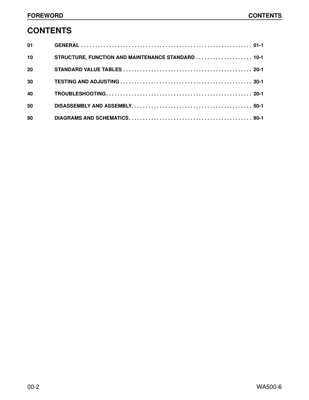
– CONTENTS
– REVISED PAGES
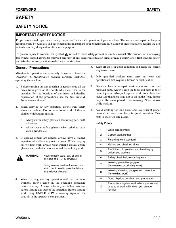
– SAFETY
— SAFETY NOTICE
— IMPORTANT SAFETY NOTICE
— General Precautions
— Preparations for Work
— Precautions During Work
– GENERAL
– HOW TO READ THE SHOP MANUAL
— Volumes
— Distribution and Updating
— Filing Method
— Revised Edition Mark
— Revisions
— Symbols
– HOISTING INSTRUCTIONS
— Hoisting
— Making Signs
— Precautions
— Precautions for Sling Work
— Precautions for Using Mobile Crane
— Precautions for Using Overhead Hoist Crane
— Selecting Wire Ropes
– AIR CONDITIONER CIRCUITS
— Precautions for Handling Hoses and Tubes
— Disconnecting Hoses and Tubes
— Connecting Hoses and Tubes
– MAINTENANCE STANDARD TERMS
– HANDLING ELECTRIC AND HYDRAULIC EQUIPMENT
— Handling Electric Equipment
— Handling Wiring Harnesses and Connectors
— Main Failures Occurring in Wiring Harness
— Removing, Installing, and Drying Connectors and Wiring Harnesses
— Handling Controller
— Troubleshooting Electric Circuits
— Handling Hydraulic Equipment
— Handling Connectors Used for Engines
— Slide Lock Type
— Pull Lock Type
— Push Lock Type
— Turn-housing Type (Round Green Connector)
– PRECAUTIONS FOR OPERATIONS
— Precautions when Carrying Out Removal Work
— Precautions when Carrying Out Installation Work
— Precautions when Completing the Operation
– PUSH-PULL COUPLER
— Type 1
— Disconnection
— Connection
— Type 2
— Disconnection
— Connection
— Type 3
— Disconnection
— Connection
– COATING MATERIALS
– STANDARD TIGHTENING TORQUE
— Standard Tightening Torques of Bolts and Nuts
— Tightening Torques for Split Flange Bolts
— Tightening Torques for O-Ring Boss Piping Joints
— Tightening Torques for O-Ring Boss Plugs
— Tightening Torques for Hoses (Taper Seal Type and Face Seal Type)
— Tightening Toques for Face Seal Joints
— For 102, 107, and 114 Engine Series (Bolts and Nuts)
— For 102, 107, and 114 Engine Series (Eye Joints)
— For 102, 107, and 114 Engine Series (Taper Screws)
– ELECTRIC WIRE CODE
— How to Read Electric Wire Code
– CONVERSION TABLES
— Method of Using the Conversion Table
01 GENERAL
– SPECIFICATIONS
— Dimension Drawing
— Specification Tables
– WEIGHT TABLE
– FUEL, COOLANT, AND LUBRICANTS
10 STRUCTURE, FUNCTION AND MAINTENANCE STANDARD
– ENGINE AND COOLING SYSTEM
— Cooling System
— Engine and Transmission Mount
— Joint
— Cooling Fan Pump
— Servo Valve
— Cooling Fan Motor
— Hydraulic Motor
— Suction Valve
— Reversible Valve
— Safety Valve
– POWER TRAIN
— Drive Line Components
— Power Train System Diagram
— Without Lockup Clutch
— With Lockup Clutch
— Drive Shaft
— Power Train Piping Diagram
— Torque Converter without Lockup Clutch
— Power Transmission Route
— Oil Flow
— Torque Converter with Lockup Clutch
— Power Transmission Route: Lockup Clutch Disengaged
— Power Transmission Route: Lockup Clutch Engaged
— Oil Flow
— Torque Converter Regulator Valve
— Transmission with Lockup Clutch
— Disc Clutch
— Power Transmission Route
— Transfer
— Transmission Control Valve (without Lockup Clutch)
— Transmission Control Value (with Lockup Clutch)
— ECMV (Electronic Control Modulation Valve)
— Pressure Control Valve and Fill Switch
— Operation of ECMV
— For Lockup Clutch
— Main Relief Valve and Torque Converter Relief Valve
— Outline
— Operation
— Lubrication Relief Valve
— Torque Converter Oil Cooler
— Torque Converter Oil Filter
— Center Support
— Axle
— Front Axle
— Rear Axle
— Differential
— Front Differential
— Front Differential (with Limited Slip Differential)
— Rear Differential
— Rear Differential (with Limited Slip Differential)
— Limited Slip Differential (if equipped)
— Final Drive
– STEERING SYSTEM
— Steering Piping Diagram
— Steering Column
— Steering Control Valve
— Steering Relief Valve
— Safety Suction Valve
— Steering Valve
— Stop Valve
— Joystick Steering Lever Linkage (if equipped)
— Steering Cylinder
— Emergency Steering (if equipped)
— Piping Diagram
— Diverter Valve (for emergency steering)
— Operation
– BRAKE SYSTEM
— Piping Diagram
— Brake Valve
— Slack Adjuster
— Accumulator Charge Valve
— PPC Relief Valve
— Accumulator (for Brake)
— Brake
— Parking Brake Control
— Parking Brake
— Parking Brake Solenoid Valve
— Emergency Parking Brake Release Valve
– UNDERCARRIAGE AND FRAME
— Axle Mount
— Center Hinge Pin
– HYDRAULIC SYSTEM
— Hydraulic Piping Diagram
— Work Equipment Control Lever Linkage
— Hydraulic Tank
— Steering Pump
— Pump Unit
— Servo Valve
— LS Valve
— CO Valve
— Work Equipment Hydraulic Pump HPV190
— LS Valve
— PC Valve
— PC-EPC Valve
— Control Valve
— CLSS (Closed Center Load-Sensing System)
— Function and Operation of Each Valve
— Pressure Compensation Valve
— LS Shuttle Valve
— LS Bypass Valve
— ECSS Control Valve
— Accumulator Pressure Relief Valve
— Accumulator Charge Valve
— Accumulator (for PPC Circuit)
— Work Equipment Electric Lever
– WORK EQUIPMENT
— Work Equipment Linkage
— Bucket
— Bucket 5.6 M3 (with Bolt-On Cutting Edge)
— Bucket 5.2 M3 (with Teeth and Segment Edge)
— Bucket Positioner and Boom Kickout
— Work Equipment Lubrication
– CAB AND ITS ATTACHMENTS
— ROPS Cab
— Air Conditioner
— Air Conditioner Piping Diagram
— Cooling Circuit Diagram
— Air Conditioner Unit
— Condenser
— Receiver
— Air Conditioner Panel
– ELECTRICAL SYSTEM
— Machine Monitor System
— Machine Monitor Circuits
— Machine Monitor
— Machine Monitor Operation Switches
— Items Displayed on Monitor
— Character Display Function
— Operator Mode Functions
— Service Mode Functions
— Service Mode Menu
— Electrical System Failure History Display Function
— Mechanical System Failure History Display Function
— Real-Time Monitor Function
— Engine Reduced-Cylinder (Cylinder Cut-out) Function
— No Injection Cranking Function
— Adjustment Function
— Maintenance Monitoring Function
— Operating Information Display Function
— Optional Device Selecting Function
— Machine Serial Number Input Function
— Model Selection Function
— Load Meter Function (if equipped)
— Rear Side of Machine Monitor
— Connector Signal Tables
— Work Equipment Control System
— Work Equipment Controller
— Work Equipment Controls
— Remote Positioner
— Lift Arm Positioner
— Semi-Automatic Digging
— Pump Swash Plate Control
— Joystick Steering Control
— Real-Time Monitor
— Diagnosis
— Input and Output Signals
— Transmission Controller System
— Electrical Circuit Diagram
— Transmission Controller Gearshifting Control
— Auto-Shift Points Table
— Transmission Controller Protection Function
— Engine Control
— Transmission Cutoff Control
— ECSS Function
— Economy Lamp
— Cooling Fan Control
— Right FNR Switch Control (if equipped)
— Joystick Control
— Real-Time Monitor
— Diagnosis
— Input and Output Signals
– ELECTRONIC TRANSMISSION CONTROL
— Combination Switch
— Engine Starting Circuit
— Engine Stopping Circuit
— Preheating Circuit
— Parking Brake Circuit
— Backup and Stop Lamp circuit
— Small Lamp and Head Lamp Circuits
— Working Lamp Circuit
— Horn Circuit
— Wiper and Window Washer Circuits
— Sensors and Switches
— Input Shaft Speed Sensor
— Output Shaft Speed Sensor
— Left Brake Pressure Sensor
— Transmission Oil Temperature Sensor
— Torque Converter Oil Temperature Sensor
— Hydraulic Oil Temperature Sensor
— Axle Oil Temperature Sensor
— Kickdown Hold Switch
— Joystick Knob (if equipped)
— Right FNR Switch (if equipped)
— Lift Arm Angle Sensor (if equipped)
— Loader Pump Pressure Sensor
— Lift Arm Cylinder Bottom Pressure Sensor
— Lift Arm Cylinder Head Pressure Sensor (Load Meter) (if equipped)
— Fuel Level Sensor
— Parking Brake Pressure Switch
— Stop Lamp Pressure Switch
— Air Cleaner Clogging Sensor
— Transmission Clogging Sensor
— Steering Oil Pressure Sensor Switch
— Radiator Coolant Level Sensor
— Brake Accumulator Pressure Switch (front and rear)
— Battery Electrolyte Level Sensor
— Accelerator Pedal Sensor
— Emergency Brake Pressure Switch (front)
— Emergency Brake Pressure Switch (rear)
– KOMTRAX SYSTEM
— KOMTRAX Terminal System
— KOMTRAX Terminal
— Input and Output Signals
20 STANDARD VALUE TABLES
– STANDARD VALUE TABLES
— Standard Service Value Table for Engine
— Standard Service Value Table for Chassis
– MACHINE POSTURE
30 TESTING AND ADJUSTING
– TOOLS
— Tools for Testing, Adjusting, and Troubleshooting
– ENGINE COMPONENTS
— Measuring Engine Speed
— Measuring Exhaust Gas Color
— Using Handy Smoke Checker (A1)
— Using Smoke Meter (A2)
— Measuring Exhaust Temperature
— Adjusting Valve Clearance
— Testing Compression Pressure
— Measuring Blow-By Pressure
— Measuring Engine Oil Pressure
— Measuring Intake Air (Boost) Pressure
– FUEL SYSTEM
— Handling Fuel System Equipment
— Releasing Residual Pressure in Fuel System
— Testing Fuel Pressure
— Testing Fuel Return Rate and Leakage
— Bleeding Air from Fuel Circuit
— Testing Leakage in Fuel System
— Handling Reduced-Cylinder Mode Operation
— Handling No-Injection Cranking Operation
— Handling Controller Voltage Circuit
– BELTS
— Alternator Belt Tension
— Air Conditioner Compressor Belt Tension
– TRANSMISSION SPEED SENSOR
– DIRECTIONAL LEVER
– POWER TRAIN OIL PRESSURES
— Measuring
— Transmission Main Relief Pressure
— Torque Converter Relief Pressure
— Torque Converter Outlet Pressure
— Lockup Clutch Pressure
— F (Forward) Clutch Pressure
— R (Reverse) Clutch Pressure
— 1st Clutch Pressure
— 2nd Clutch Pressure
— 3rd Clutch Pressure
— 4th Clutch Pressure
— Lubrication Pressure
— Adjusting
— Transmission Main Relief Valve
— Torque Converter Relief Valve
– FLUSHING TRANSMISSION SYSTEM
— Torque Converter and Transmission Hydraulic Circuit
– WHEN TRANSMISSION VALVE FAILS
— Moving Machine when Transmission Valve is Broken
– STEERING SYSTEM
— Steering Stop Valve
— Testing
— Adjusting
— Steering Wheel
— Measuring Play
— Measuring Operating Effort
— Measuring Operating Time
— Steering Oil Pressure
— Measuring Steering Relief Pressure
— Measuring Pilot Circuit Pressure
— Measuring LS Circuit Pressure
— Adjusting Steering Relief Pressure
— Bleeding Air From Steering Cylinder Circuit
– HYDRAULIC FAN
— Measuring Fan Speed
— Measuring Fan Drive Oil Pressure
— Measuring Fan Reverse Solenoid Output Pressure
— Bleeding Air from Hydraulic Drive Fan Circuit
– BRAKE SYSTEM
— Measuring Brake Pedal
— Measuring Brake Performance
— Accumulator Charge Pressure
— Testing Wheel Brake Oil Pressure
— Measuring Wear of Brake Disc
— Bleeding Air from Brake Circuit
— Bleeding Air from Slack Adjuster
— Bleeding Air from Brake Cylinder
— Releasing Residual Pressure in Brake Accumulator Circuit
— Parking Brake
— Testing Parking Brake Performance
— Measuring Parking Brake Oil Pressure
— Testing Wear of Parking Brake Disc
— Releasing Parking Brake Manually
– WORK EQUIPMENT
— Control Lever
— Measuring Operating Effort
— Measuring Stroke
— PPC Oil Pressure
— Shutoff Valve Basic Pressure
— Shutoff Valve Output Pressure
— Oil Pressure
— Preparation Work
— Measuring Work Equipment Relief Pressure
— Measuring Unload Pressure
— Measuring LS Differential Pressure
— Adjusting Unload Valve
— Adjusting Work Equipment Relief Pressure
— Adjusting LS Differential Pressure
— Bleeding Air from Work Equipment Circuit
— From Work Equipment Pump (piston pump)
— From Hydraulic Cylinder
— Releasing Residual Pressure in Hydraulic Circuit
— Between Respective Hydraulic Cylinders and Control Valve
— From ECSS (Travel Damper) Circuit
— Moving Machine When Removing Operator Cab
— Bucket Positioner
— Testing and Adjusting
— Adjusting Clearance
— Adjusting Bucket-Levelness Detecting Proximity Switch
— Adjusting Maximum Tilt-Detecting Proximity Switch
— Position-Detecting Lever
— Checking Proximity Switch Operation Pilot Lamp
– ELECTRICAL SYSTEM
— Troubleshooting
— Procedure for Testing Diodes
— Using Digital-Type Circuit Tester
— Using Analog-Type Circuit Tester
— Preparation Work for Troubleshooting Electrical System
— Machine Monitor
— Transmission Controller
— Work Equipment Controller
— KOMTRAX Terminal
– KOMTRAX TERMINAL SYSTEM
— Starting KOMTRAX Terminal Operations
— Station Opening Check in Machine Side
— Application for the Start of Use
— KOMTRAX Terminal Indicator Lamps (if equipped)
– MACHINE MONITOR SYSTEM
— Adjusting Replaced, Reassembled, or Added Sensors and Controllers
— Adjustment for User’s Needs
— Normal and Special Functions of Machine Monitor
— Normal Functions: Operator Mode
— Special Functions: Service Mode
— Functions and Flow of Service Mode
— Operator Mode
— Service Meter/Clock Display Function (1)
— Load Meter Function (if equipped) (2)
— Odometer Display Function (3)
— Maintenance Monitoring Function (4)
— Telephone Number Input Function (5)
— Language Selection Function (6)
— Monitor Brightness Adjustment Function (7)
— Time Adjustment Function (8)
— Travel Speed/Engine Speed Display Selecting Function (9)
— Travel Speed/Engine Speed Display/Non-Display Selecting Function (10)
— Action Code Display Function (11)
— Failure Code Display Function (12)
— Service Mode
— Switching to Service Mode and Screen Display (1)
— Electrical System Failure History Display Function (ELECTRIC FAULT) (2)
— Mechanical System Failure History Display Function (MACHINE FAULT) (3)
— Real-Time Monitoring Function (REAL-TIME MONITOR) (4)
— Real-Time Monitoring Codes Tables
— Cylinder Cutout Function (CYLINDER CUT-OUT) (5)
— No-Injection Cranking Function (NO INJECTION) (6)
— Adjustment Function (TUNING) (7)
— Maintenance Monitoring Function (MAINTENANCE MONITOR) (8)
— Operating Information Display Function (OPERATION INFO) (9)
— Optional Device Selecting Function (OPTIONAL SELECT) (10)
— Machine Serial Number Input Function (MACHINE No. SET) (11)
— Model Selection Function (MACHINE WA500) (12)
— Initialize Function (INITIALIZE) (13)
– PM CLINIC INSPECTION TABLES
40 TROUBLESHOOTING
– TROUBLESHOOTING POINTS
– TROUBLESHOOTING EVENTS
– MAINTENANCE PRECAUTIONS
— Precautions when Handling Electrical Equipment
— Handling Electronic Control Unit
— Points to Remember when Troubleshooting Electrical Circuits
– ELECTRIC WIRE CODE
— How to Read Electric Wire Code
— Type, Symbol, and Material
— Dimensions
— Color Codes Table
— Circuits and Color Codes
— Classification by Thickness
– HANDLING HYDRAULIC EQUIPMENT
– CHECKS BEFORE TROUBLESHOOTING
— Categories and Method of Using Troubleshooting Charts
— Troubleshooting Individual Electrical Circuits
— Chart Use
— Chart Tips
— Troubleshooting Individual Hydraulic Circuits
– CONNECTOR PIN NUMBERS
— Connection Tables for Connector PIN Numbers
— X-Type Connectors
— SWP-Type Connectors
— M-Type Connectors
— S-Type Connectors
— MIC-Type Connectors
— AMP040-Type Connectors
— AMP070-Type Connectors
— AMP Connector
— L-Type Connector
— PA-Type Connector
— Bendix (MS) Connector
— KES1 (Automobile) Connectors
— F-Type Connector
— Connectors for Relay (Socket-Type)
— HD30 Series Connectors
— DT Series Connectors
— DTM Series Connectors
— DTHD Series Connectors
— DTP Series Connectors
— DRC26 Series Connectors
— DRC12, 16 Series Connectors
— AMP Connectors for Pump Controller (CH700)
— BOSCH Connectors for Engine
— SUMITOMO Connectors for Engine
— CANNON Connector for Engine
— AMP Connectors for Engine
— FRAMATOME Connectors for Engine
— PACKARD Connectors for Engine
— DT Series Connectors for Engine
– T-BRANCH BOX and T-BRANCH ADAPTER TABLE
– MODE CHART
– INFORMATION IN TESTING PROCEDURES
– TROUBLESHOOTING BY FAILURE CODE
— Failure Code Table
– FUSE BOX AND SLOW-BLOW FUSES
— Connection Table
— Fuse Box A
— Fuse Box B
— Slow-Blow Fuses
– FAILURE CODES
– 1500LO
— TORQFLOW Transmission: Double Meshing
– 15BONX
— Transmission Filter: Clogging
– 15SAL1
— ECMV F Clutch: When Command Current is OFF, Fill Signal is ON
– 15SALH
— ECMV F Clutch: When Command Current is ON, Fill Signal is OFF
– 15SBL1
— ECMV R Clutch: When Command Current is OFF, Fill Signal is ON
– 15SBLH
— ECMV R Clutch: When Command Current is ON, Fill Signal is OFF
– 15SEL1
— ECMV 1st Clutch: When Command Current is OFF, Fill Signal is ON
– 15SELH
— ECMV 1st Clutch: When Command Current is ON, Fill Signal is OFF
– 15SFL1
— ECMV 2nd Clutch: When Command Current is OFF, FIll Signal is ON
– 15SFLH
— ECMV 2nd Clutch: When Command Current is ON, Fill Signal is OFF
– 15SGL1
— ECMV 3rd Clutch: When Command Current is OFF, Fill Signal is ON
– 15SGLH
— ECMV 3rd Clutch: When Command Current is ON, Fill Signal is OFF
– 15SHL1
— ECMV 4th Clutch: When Command Current is OFF, Fill Signal is ON
– 15SHLH
— ECMV 4th Clutch: When Command Current is ON, Fill Signal is OFF
– 2F00MA
— Parking Brake: Malfunction
– 2G42ZG
— Front Accumulator: Low Oil Pressure
– 2G43ZG
— Rear Accumulator: Low Oil Pressure
– 44K0L4
— Bucket Positioner: ON/OFF Signals Disagree
– AA1ANX
— Air Cleaner: Clogging
– AB00L6
— Alternator: Signal Disagrees with Operating State of Engine
– AB00MA
— Alternator: Malfunction
– B@BAZG
— Engine: Low Engine Oil Pressure
– B@BAZK
— Engine Oil: Low Level
– B@BCNS
— Engine: Coolant: Overheating
– B@BCZK
— Engine: Coolant: Low Level
– B@C7NS
— Brake: Brake Oil: Overheating
– b@CENS
— Torque Converter Oil: Overheating
– B@CENS
— Torque Converter Oil: Overheating
– B@GAZK
— Battery Electrolyte: Low Level
– B@HANS
— Hydraulic Oil: Overheating
– CA111
— Abnormality in Engine Controller
– CA115
— Engine Ne or Bkup Speed Sensor Error
– CA122
— Charge Pressure Sensor High Error
– CA123
— Charge Pressure Sensor Low Error
– CA131
— Throttle Sensor High Error
– CA132
— Throttle Sensor Low Error
– CA135
— Engine Oil Pressure Sensor High Error
– CA141
— Engine Oil Pressure Sensor Low Error
– CA144
— Coolant Temperature Sensor High Error
– CA145
— Coolant Temperature Sensor Low Error
– CA153
— Charge Temperature Sensor High Error
– CA154
— Charge Temperature Sensor Low Error
– CA187
— Sensor Power Supply 2 Low Error
– CA221
— Atmospheric Pressure Sensor High Error
– CA222
— Atmospheric Pressure Sensor Low Error
– CA227
— Sensor Power Supply 2 High Error
– CA234
— Engine Overspeed
– CA238
— Ne Speed Sensor Power Supply Error
– CA263
— Fuel Temperature Sensor High Error
– CA265
— Fuel Temperature Sensor Low Error
– CA271
— PCV1 Short Circuit
– CA272
— PCV1 Disconnection
– CA273
— PCV2 Short Circuit
– CA274
— PCV2 Disconnection
– CA322
— Injector #1 (L/B #1) Open/Short Error
– CA323
— Injector #5 (L/B #5) Open/Short Error
– CA324
— Injector #3 (L/B #3) Open/Short Error
– CA325
— Injector #6 (L/B #6) Open/Short Error
– CA331
— Injector #2 (L/B #2) Open/Short Error
– CA332
— Injector #4 (L/B #4) Open/Short Error
– CA342
— Calibration Code Data Inconsistency
– CA351
— Injectors Drive Circuit Error
– CA352
— Sensor Power Supply 1 Low Error
– CA386
— Sensor Power Supply 1 High Error
– CA431
— Idle Validation Switch Error
– CA432
— Idle Validation Action Error
– CA441
— Battery Voltage Low Error
– CA442
— Battery Voltage High Error
– CA449
— Common Rail Pressure High Error 2
– CA451
— Common Rail Pressure Sensor High Error
– CA452
— Common Rail Pressure Sensor Low Error
– CA553
— Common Rail Pressure High Error 1
– CA554
— Common Rail Pressure In-Range Error
– CA559
— Supply Pump Pressure Very Low Error 1
— Checksheet for No-Pressure Feed
– CA689
— Engine Ne Speed Sensor Error
– CA731
— Engine Bkup Speed Sensor Phase Error
– CA757
— All Continuous Data Lost Error
– CA778
— Engine Bkup Speed Sensor Error
– CA1228
— EGR Valve Servo Error 1
– CA1625
— EGR Valve Servo Error 2
– CA1626
— Bypass Valve Solenoid Current High Error
– CA1627
— Bypass Valve Solenoid Drive Circuit Disconnection Error
– CA1628
— Bypass Valve Servo Error 1
– CA1629
— Bypass Valve Servo Error 2
– CA1631
— Bypass Valve Lift Sensor High Error
– CA1632
— Bypass Valve Lift Sensor Low Error
– CA1633
— KOMNET Datalink Timeout Error
– CA1642
— Abnormally Low Signal in EGR Inlet Pressure Sensor
— EGR Inlet Pressure Sensor Low Error
– CA1653
— Abnormally High Signal in EGR Inlet Pressure Sensor
— EGR Inlet Pressure Sensor High Error
– CA2185
— Throttle Sensor Supply Voltage High Error
– CA2186
— Throttle Sensor Power Supply Low Error
– CA2249
— Supply Pump Pressure Very Low Error 2
– CA2271
— EGR Valve Lift Sensor High Error
– CA2272
— EGR Valve Lift Sensor Low Error
– CA2351
— EGR Valve Solenoid Operation Short Circuit
– CA2352
— EGR Valve Solenoid Operation Disconnection Error
– CA2555
— Intake Heater Relay Disconnection Error
– CA2556
— Intake Heater Relay Short Circuit Error
– D160KZ
— Backup Lamp Relay: Disconnection or Short Circuit
– D191KA
— Joystick Steering Neutral Safety Relay: Disconnection
– D191KB
— Joystick Steering Neutral Safety Relay: Short Circuit
– D192KA
— ECSS Solenoid: Disconnection
– D192KB
— ECSS Solenoid: Short Circuit
– D192KY
— ECSS Solenoid Relay: Short Circuit with Power Supply Line
– D193KA
— Joystick Steering Solenoid Cut Relay: Disconnection
– D193KB
— Joystick Steering Solenoid Cut Relay: Short Circuit
– D193KY
— Joystick Steering Solenoid Cut Relay: Short Circuit with Power Supply Line
– D5ZHKA
— Terminal C Signal: Disconnection
– D5ZHKB
— Terminal C Signal: Short Circuit
– D5ZHKZ
— Terminal C Signal: Disconnection or Short Circuit
– D5ZHL6
— Terminal C Signal: Signal Does Not Match Engine Running or Stopped State
– DA80L4
— Auto-Grease Controller: ON/OFF Signals Disagree
– DAF3KK
— Machine Monitor: Low Source Voltage (input)
– DAF5KP
— Machine Monitor: Low Output Voltage
– DAFRKR
— Machine Monitor: CAN Defective Communication
– DAQ0KK
— Transmission Controller: Low Source Voltage
– DAQ0KT
— Transmission Controller: Abnormality in Controller
– DAQ2KK
— Transmission Controller Load Power Supply Line: Low Source Voltage (input)
– DAQ9KQ
— Transmission Controller: Disagreement of Model Selection Signals
– DAQRKR
— Transmission Controller: CAN Defective Communication
– DAQRMA
— Transmission Controller Option Setting: Malfunction
– DB2RKR
— Engine Controller: CAN Defective Communication
– DB90KK
— Work Equipment Controller: Low Source Voltage (input)
– DB90KT
— Work Equipment Controller: Abnormality in Controller
– DB92KK
— Work Equipment Controller Load Power Supply Line: Low Source Voltage (input)
– DB95KX
— Work Equipment Controller Power Supply Output: Out-of-Input Signal Range
– DB99KQ
— Work Equipment Controller: Disagreement of Model Selection Signals
– DB9RKR
— Work Equipment Controller: CAN Defective Communication
– DB9RMA
— Work Equipment Controller Option Setting: Malfunction
– DB9RMC
— Work Equipment Controller: CAN Communication Defective Operation
– DD15LD
— Switch (Panel Switch 1 n): Switch is Kept Pressed for Long Time
– DD16LD
— Switch (Panel Switch 2 ‡): Switch is Kept Pressed for Long Time
– DD17LD
— Switch (Panel Switch 3 <): Switch is Kept Pressed for Long Time
- DD18LD
-- Switch (Panel Switch 4 >): Switch is Kept Pressed for Long Time
– DD1ALD
— Remote Positioner Raise/Lower Set Switch (raise): Switch Is Kept Pressed for Long Time
– DD1BLD
— Remote Positioner Raise/Lower Set Switch (lower): Switch is Kept Pressed for Long Time
– DD1CLD
— Load Meter Subtotal Switch: Switch is Kept Pressed for Long Time
– DD1FLD
— Load Meter Mode Selector Switch (A/B): Switch is Kept Pressed for Long Time
– DD1GLD
— Load Meter Mode Selector Switch (+/-): Switch is Kept Pressed for Long Time
– DD1HLD
— Load Meter Display Selector Switch: Switch is Kept Pressed for Long Time
– DDA7L4
— RPM Set ON/OFF Switch: ON/OFF Signals Disagree
– DDA8KB
— RPM Set Idle UP/DOWN Selector Switch (idle UP): Short Circuit
– DDA9KB
— RPM Set Idle UP/DOWN Selector Switch (idle DOWN): Short Circuit
– DDB6L4
— Parking Brake Switch (Neutralizer): ON/OFF Signals Disagree
– DDD1LD
— Remote Positioner Bucket Angle Set Switch: Switch is Kept Pressed for Long Time
– DDE5MA
— Emergency Steering Drive Switch: Malfunction
– DDK3KA
— Right FNR Switch: Disconnection
– DDK3KB
— Right FNR Switch: Short Circuit
– DDK4KA
— Joystick Steering FNR Switch: Disconnection
– DDK4KB
— Joystick Steering FNR Switch: Short Circuit
– DDK5L4
— Joystick Steering with Shift UP/DOWN Switch: ON/OFF Signals Disagree
– DDK6KA
— FNR Lever Switch: Disconnection
– DDK6KB
— FNR Lever Switch: Short Circuit
– DDT0L4
— Shift Mode Selector Switch: ON/OFF Signals Disagree
– DDT4LD
— Transmission Cutoff Set Switch: Switch is Kept Pressed for Long Time
– DDW9LD
— Kickdown Switch: Switch is Kept Pressed for Long Time
– DDWLLD
— Hold Switch: Switch is Kept Pressed Down for Long Time
– DDY0LD
— Load Meter Cancel Switch: Switch is Kept Pressed for Long Time
– DF10KA
— Transmission Shift Lever Switch: Disconnection
– DF10KB
— Transmission Shift Lever Switch: Short Circuit
– DGF1KA
— Transmission Oil Temperature Sensor: Disconnection
– DGF1KB
— Transmission Oil Temperature Sensor: Short Circuit
– DGH2KX
— Hydraulic Oil Temperature Sensor: Out-of-Input Signal Range
– DGR2KA
— Rear Brake Oil Temperature Sensor: Disconnection
– DGR2KX
— Rear Brake Oil Pressure Sensor: Out-of-Input Signal Range
– DGT1KX
— Torque Converter Oil Temperature Sensor: Out-of-Input Signal Range
– DH21KA
— Work Equipment Pump Oil Pressure Sensor: Disconnection
– DH21KB
— Work Equipment Pump Oil Pressure Sensor: Short Circuit
– DHPCKX
— Lift Arm Cylinder Bottom Pressure Sensor: Out-of-Input Signal Range
– DHPDKX
— Lift Arm Cylinder Head Pressure Sensor: Out-of-Input Signal Range
– DHT1KX
— Left Brake Pressure Sensor: Out-of-Input Signal
– DHT2L6
— Transmission Filter Clogging Sensor: Signal Disagrees with Operating and Stopped States of Engine
– DK59KA
— Lift Arm EPC Lever Potentiometer (Main): Disconnection
– DK59KY
— Lift Arm EPC Lever Potentiometer (Main): Short Circuit with Power Supply Line
– DK59L8
— Lift Arm EPC Lever Potentiometer (Main): Analog Signals Disagree
– DK5AKA
— Lift Arm EPC Lever Potentiometer (Sub): Disconnection
– DK5AKY
— Lift Arm EPC Lever Potentiometer (Sub): Short Circuit with Power Supply LIne
– DK5BKA
— Bucket EPC Lever Potentiometer (Main): Disconnection
– DK5BKY
— Bucket EPC Lever Potentiometer (Main): Short Circuit with Power Supply Line
– DK5BL8
— Bucket EPC Lever Potentiometer (Main): Analog Signals Disagree
– DK5CKA
— Bucket EPC Lever Potentiometer (Sub): Disconnection
– DK5CKY
— Bucket EPC Lever Potentiometer (Sub): Short Circuit with Power Supply Line
– DK5DKA
— 3-Spool Valve (Attachment) EPC Lever Potentiometer (Main): Disconnection
– DK5DKY
— 3-Spool Valve (Attachment) EPC Lever Potentiometer (Main): Short Circuit with Power Supply Line
– DK5DL8
— 3-Spool Valve (Attachment) EPC Lever Potentiometer (Main): Analog Signals Disagree
– DK5EKA
— 3-Spool Valve (Attachment) EPC Lever Potentiometer (Sub): Disconnection
– DK5EKY
— 3-Spool Valve (Attachment) EPC Lever Potentiometer (Sub): Short Circuit with Power Supply Line
– DK5FKA
— Joystick Steering EPC Lever Potentiometer (Main): Disconnection
– DK5FKY
— Joystick Steering EPC Lever Potentiometer (Main): Short Circuit with Power Supply Line
– DK5GKA
— Joystick Steering EPC Lever Potentiometer (Sub): Disconnection
– DK5GKY
— Joystick Steering EPC Lever Potentiometer (Sub): Short Circuit with Power Supply Line
– DK5FL8
— Joystick Steering EPC Lever Potentiometer (Main): Analog Signals Disagree
– DKA0KA
— Lift Arm Angle Sensor: Disconnection
– DKA0KX
— Lift Arm Angle Sensor: Out-of-Input Signal Range
– DKA0KY
— Lift Arm Angle Sensor: Short Circuit with Power Supply Line
– DKA0L0
— Lift Arm Angle Sensor: Double Meshing
– DLF1KA
— Transmission Input Shaft Speed Sensor: Disconnection
– DLF1LC
— Transmission Input Shaft Speed Sensor: Speed Signals Disagree
– DLT4KB
— Transmission Input Shaft Speed Sensor: Short Circuit
– DLT4KX
— Transmission Output Shaft Speed Sensor: Out-of-Input Signal Range
– DT20KB
— Transmission Cutoff Indicator Lamp: Short Circuit
– DUM1KB
— Remote Positioner Raise Set Indicator Lamp: Short Circuit
– DUM2KB
— Remote Positioner Lower Set Indicator Lamp: Short Circuit
– DV00KB
— Alarm Buzzer: Short Circuit
– DW4PKA
— Lift Arm Raise EPC Solenoid: Disconnection
– DW4PKB
— Lift Arm Raise EPC Solenoid: Short Circuit
– DW4PKY
— Lift Arm Raise EPC Solenoid: Short Circuit with Power Supply Line
– DW4QKA
— Lift Arm Lower EPC Solenoid: Disconnection
– DW4QKB
— Lift Arm Lower EPC Solenoid: Short Circuit
– DW4QKY
— Lift Arm Lower EPC Solenoid: Short Circuit with Power Supply Line
– DW4RKA
— Bucket Tilt EPC Solenoid: Disconnection
– DW4RKB
— Bucket Tilt EPC Solenoid: Short Circuit
– DW4RKY
— Bucket Tilt EPC Solenoid: Short Circuit with Power Supply Line
– DW4SKA
— Buck Dump EPC Solenoid: Disconnection
– DW4SKB
— Bucket Dump EPC Solenoid: Short Circuit
– DW4SKY
— Bucket Dump EPC Solenoid: Short Circuit with Power Supply Line
– DW7BKA
— Fan Reverse Solenoid: Disconnection
– DW7BKB
— Fan Reverse Solenoid: Short Circuit
– DW7BKY
— Fan Reverse Solenoid: Short Circuit with Power Supply Line
– DW7DKA
— Hydraulic Drive Fan Neutral Solenoid: Disconnection
– DW7DKB
— Hydraulic Drive Fan Neutral Solenoid: Short Circuit
– DW7DKY
— Hydraulic Drive Fan Solenoid: Short Circuit with Power Supply Line
– DWM1KA
— Work Equipment Neutral Lock Solenoid: Disconnection
– DWM1KB
— Work Equipment Neutral Lock Solenoid: Short Circuit
– DWM1KY
— Work Equipment Neutral Lock Solenoid: Short Circuit with Power Supply Line
– DWN6KA
— Lift Arm Raise Magnet Detent Solenoid: Disconnection
– DWN6KB
— Lift Arm Raise Magnet Detent Solenoid: Short Circuit
– DWN6KY
— Lift Arm Raise Magnet Detent Solenoid: Short Circuit with Power Supply Line
– DWN7KA
— Lift Arm Float Magnet Detent Solenoid: Disconnection
– DWN7KB
— Lift Arm Float Magnet Detent Solenoid: Short Circuit
– DWN7KY
— Lift Arm Float Magnet Detent Solenoid: Short Circuit with Power Supply Line
– DWN8KA
— Bucket Tilt Magnet Detent Solenoid: Disconnection
– DWN8KB
— Bucket Tilt Magnet Detent Solenoid: Short Circuit
– DWN8KY
— Bucket Tilt Magnet Detent Solenoid: Shorted with the Power Source
– DX16KA
— Fan Pump EPC Solenoid: Disconnection
– DX16KB
— Fan Pump EPC Solenoid: Short Circuit
– DX16KY
— Fan Pump EPC Solenoid: Short Circuit with Power Supply Line
– DXA1KA
— Pump PC-EPC Solenoid: Disconnection
– DXA1KB
— Pump PC-EPC Solenoid: Short Circuit
– DXH1KA
— Lockup ECMV Solenoid: Disconnection
– DXH1KB
— Lockup ECMV Solenoid: Short Circuit
– DXH1KY
— Lockup ECMV Solenoid: Short Circuit with Power Supply Line
– DXH4KA
— 1st Clutch ECMV Solenoid: Disconnection
– DXH4KB
— 1st Clutch ECMV Solenoid: Short Circuit
– DXH4KY
— 1st Clutch ECMV Solenoid: Short Circuit with Power Supply Line
– DXH5KA
— 2nd Clutch ECMV Solenoid: Disconnection
– DXH5KB
— 2nd Clutch ECMV Solenoid: Short Circuit
– DXH5KY
— 2nd Clutch ECMV Solenoid: Short Circuit with Power Supply Line
– DXH6KA
— 3rd Clutch ECMV Solenoid: Disconnection
– DXH6KB
— 3rd Clutch ECMV Solenoid: Short Circuit
– DXH6KY
— 3rd Clutch ECMV Solenoid: Short Circuit with Power Supply Line
– DXH7KA
— R Clutch ECMV Solenoid: Disconnection
– DXH7KB
— R Clutch ECMV Solenoid: Short Circuit
– DXH7KY
— R Clutch ECMV Solenoid: Short Circuit with Power Supply Line
– DXH8KA
— F Clutch ECMV Solenoid: Disconnection
– DXH8KB
— F Clutch ECMV Solenoid: Short Circuit
– DXH8KY
— F Clutch ECMV Solenoid: Short Circuit with Power Supply Line
– DXHHKA
— 4th Clutch ECMV Solenoid: Disconnection
– DXHHKB
— 4th Clutch ECMV Solenoid: Short Circuit
– DXHHKY
— 4th Clutch ECMV Solenoid: Short Circuit with Power Supply Line
– DXHJKA
— 3-Spool Valve Extract EPC Solenoid: Disconnection
– DXHJKB
— 3-Spool Valve Extract EPC Solenoid: Short Circuit
– DXHJKY
— 3-Spool Valve Extract EPC Solenoid: Short Circuit with Power Supply Line
– DXHKKA
— 3-Spool Valve Retract EPC Solenoid: Disconnection
– DXHKKB
— 3-Spool Valve Retract EPC Solenoid: Short Circuit
– DXHKKY
— 3-Spool Valve Retract EPC Solenoid: Short Circuit with Power Supply Line
– DXHLKA
— Joystick Steering Right EPC Solenoid: Disconnection
– DXHLKB
— Joystick Steering Right EPC Solenoid: Short Circuit
– DXHLKY
— Joystick Steering Right EPC Solenoid: Short Circuit with Power Supply Line
– DXHMKA
— Joystick Steering Left EPC Solenoid: Disconnection
– DXHMKB
— Joystick Steering Left EPC Solenoid: Short Circuit
– DXHMKY
— Joystick Steering Left EPC Solenoid: Short Circuit with Power Supply Line
– TROUBLESHOOTING: E-MODE
— Troubleshooting Electrical System
— Information in Troubleshooting Table
– E-1
— Engine Does Not Start
– E-2
— Wiper Does Not Operate
– E-3
— Windshield Washer Does Not Operate
– E-4
— Headlamp, Clearance Lamp, Tail Lamp, and License Lamp Do Not Light Up or Go Off
– E-5
— Working Lamp Does Not Light Up or Go Off
– E-6
— Turn Signal Lamp and Hazard Lamp Do Not Light Up or Go Off
– E-7
— Brake Lamp Does Not Light or It Keeps Lighting Up
– E-8
— Backup Lamp Does Not Light or It Keeps Lighting Up
– E-9
— Backup Buzzer Does Not Sound or It Keeps Sounding
– E-10
— Horn Does Not Sound or It Keeps Sounding
– E-11
— Alarm Buzzer Does Not Sound or It Keeps Sounding
– E-12
— Air Conditioner Does Not Operate or Stop
– E-13
— KOMTRAX System Does Not Work Properly
— Lamp Display Section of KOMTRAX Terminal
– TROUBLESHOOTING: H-MODE
— Troubleshooting Hydraulic and Mechanical Systems
— Using Troubleshooting Chart
— Failure Codes and Causes Table
– H-1
— Machine Does Not Start
– H-2
— Torque Converter Lockup is Not Switched OFF (Engine Stalls)
– H-3
— Torque Converter Lockup is Not Switched ON
– H-4
— Travel Speed is Slow, Thrusting Force is Weak, Uphill Traveling Power is Weak, Gear is Not Shifted
– H-5
— Large Shocks When Starting and Shifting Gears
– H-6
— Large Time Lag When Starting and Shifting Gear
– H-7
— Torque Converter Oil Temperature is High
– H-8
— Steering Does Not Turn
– H-9
— Steering Does Not Turn (Joystick Steering, if equipped)
– H-10
— Steering Response is Poor
– H-11
— Steering Turning Response is Poor (Joystick Steering, if Equipped)
– H-12
— Steering is Heavy
– H-13
— When Machine Turns, It Shakes or Jerks
– H-14
— When Machine Turns, It Shakes or Jerks (Joystick Steering, if Equipped)
– H-15
— Wheel Brake Does Not Work or Does Not Work Well
– H-16
— Wheel Brake is Not Released or It Drags
– H-17
— Parking Brake Does Not Work or Does Not Work Well
– H-18
— Parking Brake is Not Released or It Drags
– H-19
— Lift Arm Does Not Rise
– H-20
— Lift Arm is Low or Rising Force is Insufficient
– H-21
— When Rising, Lift Arm Starts to Move Slowly at a Specific Height
– H-22
— Lift Arm Cylinder Cannot Hold Down Bucket (Bucket Floats)
– H-23
— Hydraulic Drifts of the Lift Arm Occur Often
– H-24
— Lift Arm Wobbles During Operation
– H-25
— Bucket Does Not Tilt Back
– H-26
— Bucket Speed is Low or Tilting-Back Force Is Insufficient
– H-27
— Bucket Starts to Operate Slowly in the Midst of Tilting Back
– H-28
— Bucket Cylinder Cannot Hold Down the Bucket
– H-29
— Hydraulic Drifts of the Bucket Occur Often
– H-30
— Bucket Wobbles During Travel with Load
– H-31
— During Operation of Machine, Engine Speed Drops Remarkably or Engine Stalls
– H-32
— Large Shocks When Work Equipment Starts and Stops
– H-33
— When Work Equipment Circuit is Relieved Singly, Other Work Equipment Moves
– H-34
— ECSS Does Not Operate; Pitching and Bouncing Occur
50 DISASSEMBLY AND ASSEMBLY
– HOW TO READ THIS MANUAL
— Removal and Installation of Assemblies
— Disassembly and Assembly of Assemblies
– COATING MATERIALS LIST
– SPECIAL TOOLS LIST
– SKETCHES OF SPECIAL TOOLS
– CONNECTOR REPAIR PROCEDURES
— Stripping Insulation
— Wire Inspection
— Contact Terminal Removal (HD30 Type)
— Crimping Contact Terminal (HD30 Type)
— Insertion of Contact Terminal (HD30 Type)
— Contact Terminal Removal (DT Type)
— Crimping Contact Terminal (DT Type)
— Insertion of Contact Terminal (DT Type)
– ENGINE AND COOLING SYSTEM
— Engine
— Removal
— Installation
— Radiator
— Removal
— Installation
— Air Aftercooler
— Removal
— Installation
— Cooling Fan and Fan Motor
— Removal
— Installation
— Radiator Guard and Cooling Fan
— Removal
— Installation
— Fuel Tank
— Removal
— Installation
— Engine Hood
— Removal
— Installation
— Fuel Supply Pump
— Removal
— Installation
— Cylinder Head
— Removal
— Installation
— Fuel Injector
— Removal
— Installation
— Engine Front Seal
— Removal
— Installation
— Engine Rear Seal
— Removal
— Installation
– POWER TRAIN
— Torque Converter and Transmission Assembly
— Removal
— Installation
— Power Train
— Preparation
— Disassembly
— Assembly
— Input Transfer
— Disassembly
— Assembly
— Torque Converter (Lockup Specification)
— Disassembly
— Assembly
— Torque Converter (Without Lockup)
— Disassembly
— Assembly
— Transmission
— Disassembly
— Assembly
— Transfer and Parking Brake Assembly
— Disassembly
— Assembly
— Front Axle
— Removal
— Installation
— Rear Axle
— Removal
— Installation
— Front Differential
— Removal
— Installation
— Differential (with Limited Slip Differential)
— Disassembly
— Assembly
— Differential (without Limited Slip Differential)
— Disassembly
— Assembly
— Final Drive (Front and Rear)
— Disassembly
— Assembly
– BRAKE SYSTEM
— Brakes (Front and Rear)
— Removal
— Installation
— Disassembly
— Assembly
— Slack Adjuster
— Brake Accumulator Charge Valve
– UNDERCARRIAGE AND FRAME
— Center Hinge Pin
— Removal
— Installation
– HYDRAULIC SYSTEM
— Hydraulic Tank
— Removal
— Installation
— Cooling Pump
— Removal
— Installation
— Fan Pump
— Removal
— Installation
— Work Equipment Pump
— Removal
— Installation
— Steering, Torque Converter Charge, and EPC Pump Assembly
— Removal
— Installation
— Work Equipment Valve
— Removal
— Installation
— Work Equipment Control Valve Assembly
— Disassembly and Assembly
— Steering Cylinder
— Disassembly
— Assembly
— Lift Arm and Bucket Cylinder
— Disassembly
— Assembly
— Steering Valve
— Removal
— Installation
– WORK EQUIPMENT
— Work Equipment
— Removal
— Installation
— Counterweight (Large)
— Removal
— Installation
— Counterweight (Small)
— Removal
— Installation
– CAB AND ITS ATTACHMENTS
— Cab (Separate Cab and Floor)
— Removal
— Installation
— Cab and Floor Frame (Cab-Floor Unit)
— Installation
— Cab Glass (Stuck Glass)
— Removal
— Installation
— Operator Seat (Upper Seat)
— Storage Box
— Seat Pad and Backrest Upholstery
— Mechanical Lumbar Support
— Armrests (if equipped)
— Backrest
— Backrest Adjustment
— Seat Angle and Seat Depth Adjuster
— Covers
— Slide Rails
— Operator Seat (Suspension)
— Top Cover
— Front Cover
— Bellows
— Bowden Pull Wire and Handle (Vertical Shock Absorber Adjustment)
— Vertical Shock Absorber
— Compressor
— Height Level Controller
— Compressed-Air Hoses
— Bowden Pull Wires and Handle (Height Adjustment)
— Pneumatic Spring
— Air Tank for Additional Air Supply
— Cable Harness
— Suspension System (Upper Part)
— Suspension System (Lower Part)
— Swinging Structure
– ELECTRICAL SYSTEM
— Engine Controller
— Removal
— Installation
— Transmission Controller
— Removal
— Installation
— Work Equipment Controller
— Removal
— Installation
— KOMTRAX Terminal
— Removal
— Installation
— Air Conditioner Unit
— Removal
— Installation
90 DIAGRAMS AND SCHEMATICS
– HYDRAULIC SYSTEM
— Power Train Hydraulic Circuit
— Without Lockup Clutch
— With Lockup Clutch
— Brake Hydraulic Circuit
— Without Forced Brake Cooling System
— With Forced Brake Cooling System
— Work Equipment
– ELECTRICAL SYSTEM
— Air Conditioner Electrical Circuit
— Electrical Circuit Diagram (1/7)
— Electrical Circuit Diagram (2/7)
— Electrical Circuit Diagram (3/7)
— Electrical Circuit Diagram (4/7)
— Electrical Circuit Diagram (5/7)
— Electrical Circuit Diagram (6/7)
— Electrical Circuit Diagram (7/7)
— Connector List and Stereogram
— Chassis
— Operator’s Compartment
— Engine and Transmission

Reviews
There are no reviews yet.