Komatsu WA800-3E0, WA900-3E0 70001 & Up, 60001 & Up SEN02034-13 (Preview)
Cover
00 Index and foreword
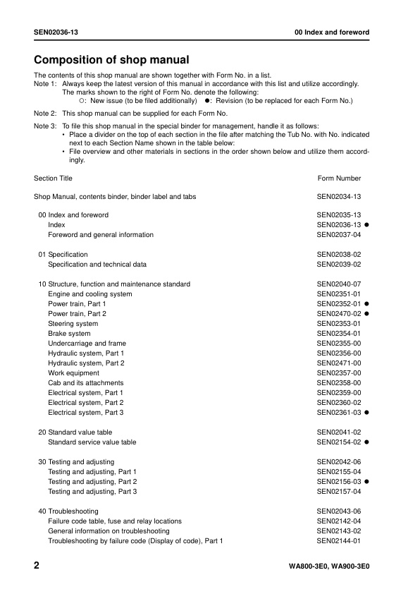
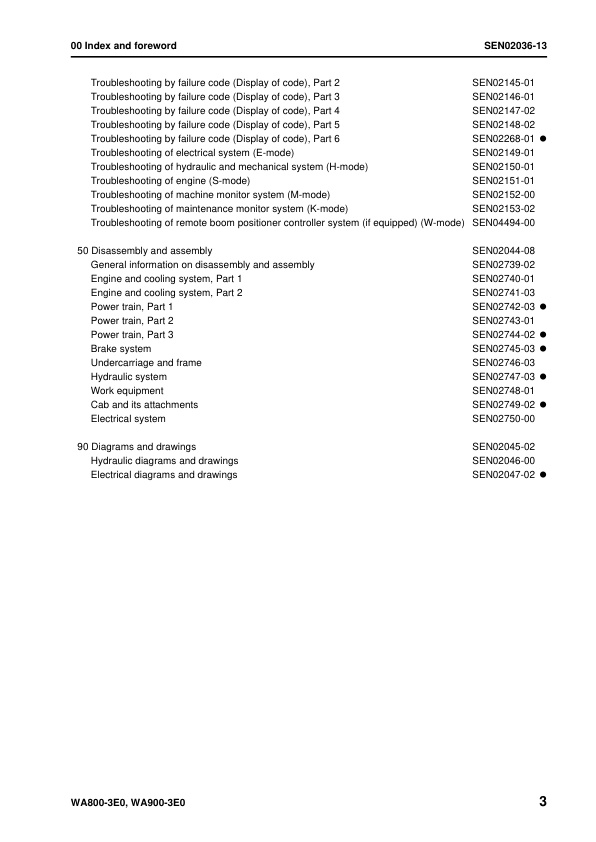
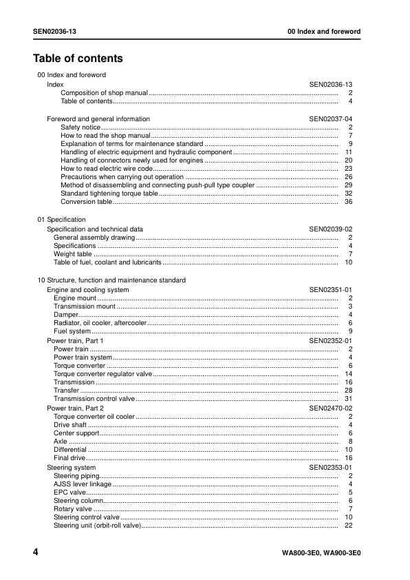
Index
Table of contents
Foreword and general information
Safety notice
How to read the shop manual
Explanation of terms for maintenance standard
Handling of electric equipment and hydraulic component
Handling of connectors newly used for engines
How to read electric wire code
Precautions when carrying out operation
Method of disassembling and connecting push-pull type coupler
Standard tightening torque table
Conversion table
01 Specification
Specification and technical data
General assembly drawing
Specifications
Weight table
Table of fuel, coolant and lubricants
10 Structure, function and maintenance standard
Engine and cooling system
Engine mount
Transmission mount
Damper
Radiator, oil cooler, aftercooler
Fuel system
Power train, Part 1
Power train
Power train system
Torque converter
Torque converter regulator valve
Transmission
Transfer
Transmission control valve
Power train, Part 2
Torque converter oil cooler
Drive shaft
Center support
Axle
Differential
Final drive
Steering system
Steering piping
AJSS lever linkage
EPC valve
Steering column
Rotary valve
Steering control valve
Steering unit (orbit-roll valve)
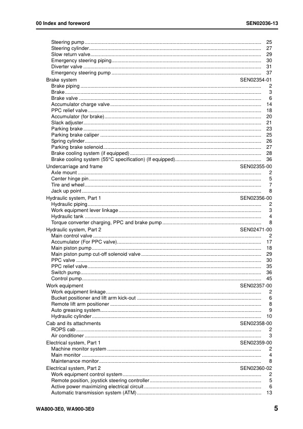
Steering pump
Steering cylinder
Slow return valve
Emergency steering piping
Diverter valve
Emergency steering pump
Brake system
Brake piping
Brake
Brake valve
Accumulator charge valve
PPC relief valve
Accumulator (for brake)
Slack adjuster
Parking brake
Parking brake caliper
Spring cylinder
Parking brake solenoid
Brake cooling system (if equipped)
Brake cooling system (55°C specification) (If equipped)
Undercarriage and frame
Axle mount
Center hinge pin
Tire and wheel
Jack up point
Hydraulic system, Part 1
Hydraulic piping
Work equipment lever linkage
Hydraulic tank
Torque conbverter charging, PPC and brake pump
Hydraulic system, Part 2
Main control valve
Accumulator (For PPC valve)
Main piston pump
Main piston pump cut-off solenoid valve
PPC valve
PPC relief valve
Switch pump
Control pump
Work equipment
Work equipment linkage
Bucket positioner and lift arm kick-out
Remote lift arm positioner
Auto greasing system
Hydraulic cylinder
Cab and its attachments
ROPS cab
Air conditioner
Electrical system, Part 1
Machine monitor system
Main monitor
Maintenance monitor
Electrical system, Part 2
Work equipment control system
Remote position, joystick steering controller
Active power maximizing electrical circuit
Automatic transmission system (ATM)
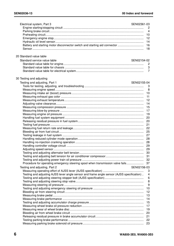
Electrical system, Part 3
Engine starting/stopping circuit
Parking brake circuit
Preheating circuit
Emergency engine stop
Hydraulic oil level sensor
Battery and starting motor disconnector switch and starting aid connector
Sensor
20 Standard value table
Standard service value table
Standard value table for engine
Standard value table for chassis
Standard value table for electrical system
30 Testing and adjusting
Testing and adjusting, Part 1
Tools for testing, adjusting, and troubleshooting
Measuring engine speed
Measuring intake air (boost) pressure
Measuring exhaust gas color
Measuring exhaust temperature
Adjusting valve clearance
Measuring compression pressure
Measuring blow-by pressure
Measuring engine oil pressure
Handling fuel system equipment
Releasing residual pressure in fuel system
Testing fuel pressure
Measuring fuel return rate and leakage
Bleeding air from fuel circuit
Testing leakage in fuel system
Handling reduced cylinder mode operation
Handling no-injection cranking operation
Handling controller voltage circuit
Adjusting speed sensor
Testing and adjusting alternator belt tension
Testing and adjusting belt tension for air conditioner compressor
Testing and adjusting power train oil pressure
Procedure for operating emergency steering spool when transmission valve fails
Testing and adjusting, Part 2
Measuring operating effort of AJSS lever (AJSS specification)
Testing and adjusting AJSS lever angle sensor and frame angle sensor (AJSS specification)
Testing and adjusting steering stopper bolt (AJSS specification)
Testing and adjusting steering stop valve
Measuring steering oil pressure
Testing and adjusting emergency steering oil pressure
Bleeding air from steering circuit
Measuring brake pedal
Measuring brake performance
Testing and adjusting accumulator charge pressure
Measuring wheel brake oil pressure reduction
Measuring wear of wheel brake disc
Bleeding air from wheel brake circuit
Releasing residual pressure in brake accumulator circuit
Testing parking brake performance
Measuring parking brake solenoid oil pressure
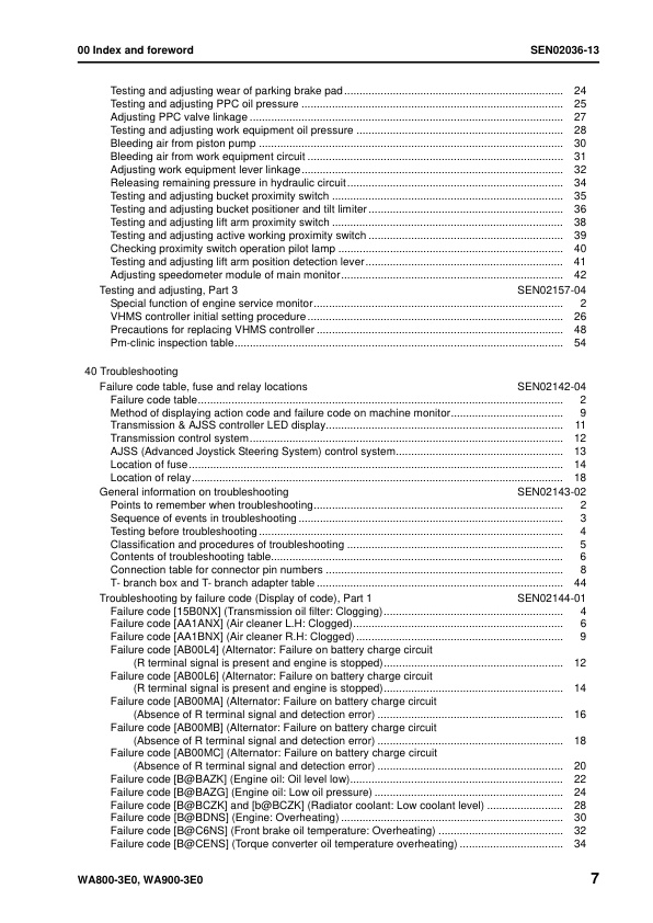
Testing and adjusting wear of parking brake pad
Testing and adjusting PPC oil pressure
Adjusting PPC valve linkage
Testing and adjusting work equipment oil pressure
Bleeding air from piston pump
Bleeding air from work equipment circuit
Adjusting work equipment lever linkage
Releasing remaining pressure in hydraulic circuit
Testing and adjusting bucket proximity switch
Testing and adjusting bucket positioner and tilt limiter
Testing and adjusting lift arm proximity switch
Testing and adjusting active working proximity switch
Checking proximity switch operation pilot lamp
Testing and adjusting lift arm position detection lever
Adjusting speedometer module of main monitor
Testing and adjusting, Part 3
Special function of engine service monitor
VHMS controller initial setting procedure
Precautions for replacing VHMS controller
Pm-clinic inspection table
40 Troubleshooting
Failure code table and fuse locations
Failure code table
Method of displaying action code and failure code on machine monitor
Transmission & AJSS controller LED display
Transmission control system
AJSS (Advanced Joystick Steering System) control system
Location of fuse
Location of relay
General information on troubleshooting
Points to remember when troubleshooting
Sequence of events in troubleshooting
Testing before troubleshooting
Classification and procedures of troubleshooting
Contents of troubleshooting table
Connection table for connector pin numbers
T- branch box and T- branch adapter table
Troubleshooting by failure code (Display of code), Part 1
Failure code [15B0NX] (Transmission oil filter: Clogging)
Failure code [AA1ANX] (Air cleaner L.H: Clogged)
Failure code [AA1BNX] (Air cleaner R.H: Clogged)
Failure code [AB00L4] (Alternator: Failure on battery charge circuit (Rterminal signal is present and engine is stopped)
Failure code [AB00L6] (Alternator: Failure on battery charge circuit (Rterminal signal is present and engine is stopped)
Failure code [AB00MA] (Alternator: Failure on battery charge circuit (Absence of R terminal signal and detection error)
Failure code [AB00MB] (Alternator: Failure on battery charge circuit (Absence of R terminal signal and detection error)
Failure code [AB00MC] (Alternator: Failure on battery charge circuit (Absence of R terminal signal and detection error)
Failure code [B@BAZK] (Engine oil: Oil level low)
Failure code [B@BAZG] (Engine oil: Low oil pressure)
Failure code [B@BCZK] and [b@BCZK] (Radiator coolant: Low coolant level)
Failure code [B@BDNS] (Engine: Overheating)
Failure code [B@C6NS] (Front brake oil temperature: Overheating)
Failure code [B@CENS] (Torque converter oil temperature overheating)
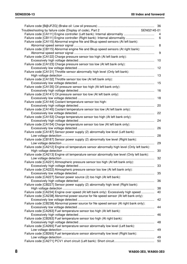
Failure code [B@JFZG] (Brake oil: Low oil pressure)
Troubleshooting by failure code (Display of code), Part 2
Failure code [CA111] Engine controller (Left bank): Internal abnormality
Failure code [CB111] Engine controller (Right bank): Internal abnormality
Failure code [CA115] Abnormal engine Ne and Bkup speed sensors (At left bank): Abnormal speed sensor signal
Failure code [CB115] Abnormal engine Ne and Bkup speed sensors (At right bank): Abnormal speed sensor signal
Failure code [CA122] Charge pressure sensor too high (At left bank only): Excessively high voltage detected
Failure code [CA123] Charge pressure sensor too low (At left bank only): Excessively low voltage detected
Failure code [CA131] Throttle sensor abnormally high level (Only left bank): High voltage detection
Failure code [CA132] Throttle sensor too low (At left bank only): Excessively low voltage detected
Failure code [CA135] Oil pressure sensor too high (At left bank only): Excessively high voltage detected
Failure code [CA141] Oil pressure sensor too low (At left bank only): Excessively low voltage detected
Failure code [CA144] Coolant temperature sensor too high: Excessively high voltage detected
Failure code [CA145] Coolant temperature sensor too low (At left bank only): Excessively low voltage detected
Failure code [CA153] Charge temperature sensor too high (At left bank only): Excessively high voltage detected
Failure code [CA154] Charge temperature sensor too low (At left bank only): Excessively low voltage detected
Failure code [CA187] Sensor power supply (2) abnormally low level (Left bank): Low voltage detection
Failure code [CB187] Sensor power supply (2) abnormally low level (Right bank): Low voltage detection
Failure code [CA212] Engine oil temperature sensor abnormally high level (Only left bank): High voltage detection
Failure code [CA213] Engine oil temperature sensor abnormally low level (Only left bank): Low voltage detection
Failure code [CA221] Atmospheric pressure sensor too high (At left bank only): Excessively high voltage detected
Failure code [CA222] Atmospheric pressure sensor too low (At left bank only): Excessively low voltage detected
Failure code [CA227] Sensor power source (2) too high (At left bank): Excessively high voltage detected
Failure code [CB227] Sensor power supply (2) abnormally high level (Right bank): High voltage detection
Failure code [CA234] Engine over speed (At left bank only): Excessively high speed
Failure code [CA238] Abnormal power source for Ne speed sensor (At left bank only): Excessively low voltage detected
Failure code [CB238] Abnormal power source for Ne speed sensor (At right bank only): Excessively low voltage detected
Failure code [CA263] Fuel temperature sensor too high (At left bank): Excessively high voltage detected
Failure code [CB263] Fuel temperature sensor too high (At right bank): Excessively high voltage detected
Failure code [CA265] Fuel temperature sensor abnormally low level (Left bank): Low voltage detection
Failure code [CB265] Fuel temperature sensor abnormally low level (Right bank): Low voltage detection
Failure code [CA271] PCV1 short circuit (Left bank): Short circuit
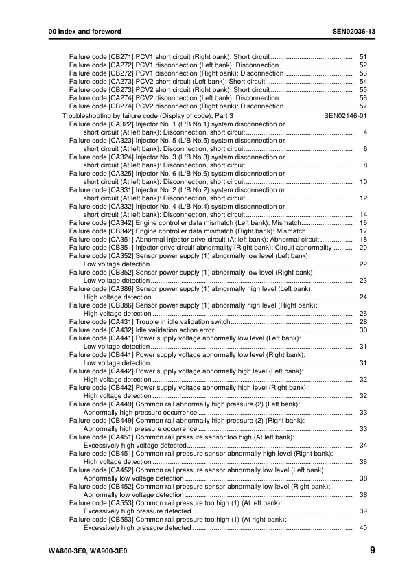
Failure code [CB271] PCV1 short circuit (Right bank): Short circuit
Failure code [CA272] PCV1 disconnection (Left bank): Disconnection
Failure code [CB272] PCV1 disconnection (Right bank): Disconnection
Failure code [CA273] PCV2 short circuit (Left bank): Short circuit
Failure code [CB273] PCV2 short circuit (Right bank): Short circuit
Failure code [CA274] PCV2 disconnection (Left bank): Disconnection
Failure code [CB274] PCV2 disconnection (Right bank): Disconnection
Troubleshooting by failure code (Display of code), Part 3
Failure code [CA322] Injector No. 1 (L/B No.1) system disconnection or short circuit (At left bank): Disconnection, short circuit
Failure code [CA323] Injector No. 5 (L/B No.5) system disconnection or short circuit (At left bank): Disconnection, short circuit
Failure code [CA324] Injector No. 3 (L/B No.3) system disconnection or short circuit (At left bank): Disconnection, short circuit
Failure code [CA325] Injector No. 6 (L/B No.6) system disconnection or short circuit (At left bank): Disconnection, short circuit
Failure code [CA331] Injector No. 2 (L/B No.2) system disconnection or short circuit (At left bank): Disconnection, short circuit
Failure code [CA332] Injector No. 4 (L/B No.4) system disconnection or short circuit (At left bank): Disconnection, short circuit
Failure code [CA342] Engine controller data mismatch (Left bank): Mismatch
Failure code [CB342] Engine controller data mismatch (Right bank): Mismatch
Failure code [CA351] Abnormal injector drive circuit (At left bank): Abnormal circuit
Failure code [CB351] Injector drive circuit abnormality (Right bank): Circuit abnormality
Failure code [CA352] Sensor power supply (1) abnormally low level (Left bank): Low voltage detection
Failure code [CB352] Sensor power supply (1) abnormally low level (Right bank): Low voltage detection
Failure code [CA386] Sensor power supply (1) abnormally high level (Left bank): High voltage detection
Failure code [CB386] Sensor power supply (1) abnormally high level (Right bank): High voltage detection
Failure code [CA431] Trouble in idle validation switch
Failure code [CA432] Idle validation action error
Failure code [CA441] Power supply voltage abnormally low level (Left bank): Low voltage detection
Failure code [CB441] Power supply voltage abnormally low level (Right bank): Low voltage detection
Failure code [CA442] Power supply voltage abnormally high level (Left bank): High voltage detection
Failure code [CB442] Power supply voltage abnormally high level (Right bank): High voltage detection
Failure code [CA449] Common rail abnormally high pressure (2) (Left bank): Abnormally high pressure occurrence
Failure code [CB449] Common rail abnormally high pressure (2) (Right bank): Abnormally high pressure occurrence
Failure code [CA451] Common rail pressure sensor too high (At left bank): Excessively high voltage detected
Failure code [CB451] Common rail pressure sensor abnormally high level (Right bank): High voltage detection
Failure code [CA452] Common rail pressure sensor abnormally low level (Left bank): Abnormally low voltage detection
Failure code [CB452] Common rail pressure sensor abnormally low level (Right bank): Abnormally low voltage detection
Failure code [CA553] Common rail pressure too high (1) (At left bank): Excessively high pressure detected
Failure code [CB553] Common rail pressure too high (1) (At right bank): Excessively high pressure detected
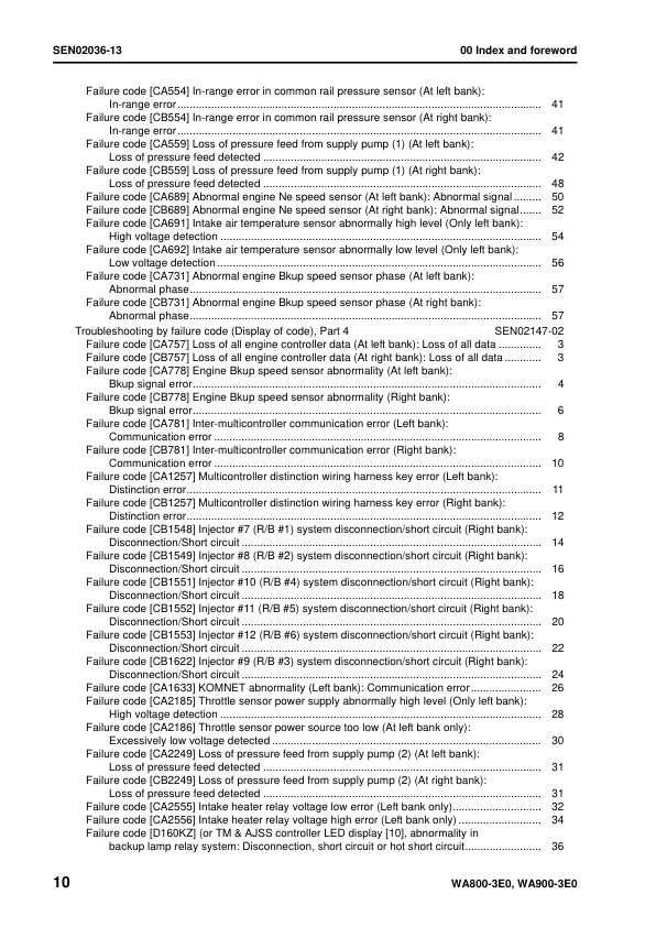
Failure code [CA554] In-range error in common rail pressure sensor (At left bank): In-range error
Failure code [CB554] In-range error in common rail pressure sensor (At right bank): In-range error
Failure code [CA559] Loss of pressure feed from supply pump (1) (At left bank): Loss of pressure feed detected
Failure code [CB559] Loss of pressure feed from supply pump (1) (At right bank): Loss of pressure feed detected
Failure code [CA689] Abnormal engine Ne speed sensor (At left bank): Abnormal signal
Failure code [CB689] Abnormal engine Ne speed sensor (At right bank): Abnormal signal
Failure code [CA691] Intake air temperature sensor abnormally high level (Only left bank): High voltage detection
Failure code [CA692] Intake air temperature sensor abnormally low level Failure code [CA692] Intake air temperature sensor abnormally low level
Failure code [CA731] Abnormal engine Bkup speed sensor phase (At left bank): Abnormal phase
Failure code [CB731] Abnormal engine Bkup speed sensor phase (At right bank): Abnormal phase
Troubleshooting by failure code (Display of code), Part 4
Failure code [CA757] Loss of all engine controller data (At left bank): Loss of all data
Failure code [CB757] Loss of all engine controller data (At right bank): Loss of all data
Failure code [CA778] Engine Bkup speed sensor abnormality (At left bank): Bkup signal error
Failure code [CB778] Engine Bkup speed sensor abnormality (Right bank): Bkup signal error
Failure code [CA781] Inter-multicontroller communication error (Left bank): Communication error
Failure code [CB781] Inter-multicontroller communication error (Right bank): Communication error
Failure code [CA1257] Multicontroller distinction wiring harness key error (Left bank): Distinction error
Failure code [CB1257] Multicontroller distinction wiring harness key error (Right bank): Distinction error
Failure code [CB1548] Injector #7 (R/B #1) system disconnection/short circuit (Right bank): Disconnection/Short circuit
Failure code [CB1549] Injector #8 (R/B #2) system disconnection/short circuit (Right bank): Disconnection/Short circuit
Failure code [CB1551] Injector #10 (R/B #4) system disconnection/short circuit (Right bank): Disconnection/Short circuit
Failure code [CB1552] Injector #11 (R/B #5) system disconnection/short circuit (Right bank): Disconnection/Short circuit
Failure code [CB1553] Injector #12 (R/B #6) system disconnection/short circuit (Right bank): Disconnection/Short circuit
Failure code [CB1622] Injector #9 (R/B #3) system disconnection/short circuit (Right bank): Disconnection/Short circuit
Failure code [CA1633] KOMNET abnormality (Left bank): Communication error
Failure code [CA2185] Throttle sensor power supply abnormally high level (Only left bank): High voltage detection
Failure code [CA2186] Throttle sensor power source too low (At left bank only): Excessively low voltage detected
Failure code [CA2249] Loss of pressure feed from supply pump (2) (At left bank): Loss of pressure feed detected
Failure code [CB2249] Loss of pressure feed from supply pump (2) (At right bank): Loss of pressure feed detected
Failure code [CA2555] Intake heater relay voltage low error (Left bank only)
Failure code [CA2556] Intake heater relay voltage high error (Left bank only)
Failure code [D160KZ] (or TM & AJSS controller LED display [10], abnormality in backup lamp relay system: Disconnection, short circuit or hot short circuit
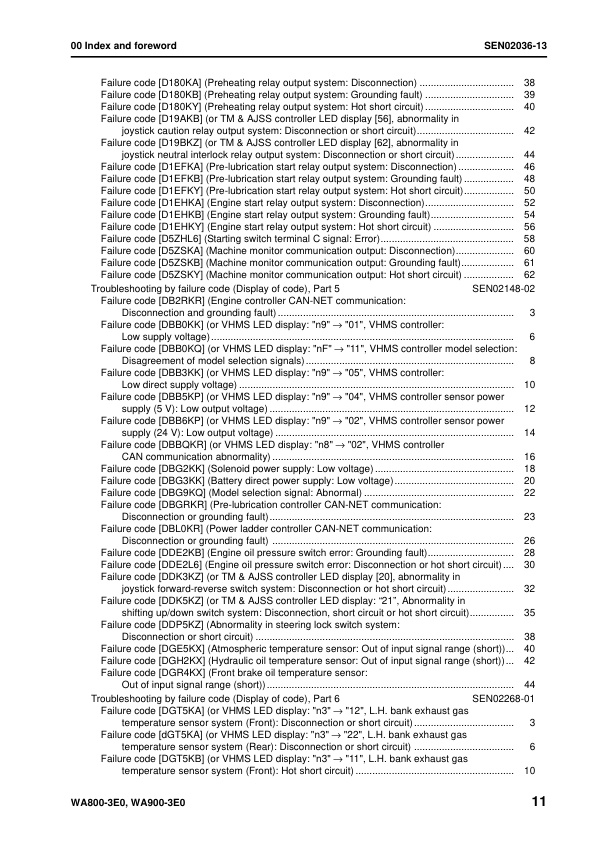
Failure code [D180KA] (Preheating relay output system: Disconnection)
Failure code [D180KB] (Preheating relay output system: Grounding fault)
Failure code [D180KY] (Preheating relay output system: Hot short circuit)
Failure code [D19AKB] (or TM & AJSS controller LED display [56], abnormality in joystick caution relay output system: Disconnection or short circuit)
Failure code [D19BKZ] (or TM & AJSS controller LED display [62], abnormality in joystick neutral interlock relay output system: Disconnection or short circuit)
Failure code [D1EFKA] (Pre-lubrication start relay output system: Disconnection)
Failure code [D1EFKB] (Pre-lubrication start relay output system: Grounding fault)
Failure code [D1EFKY] (Pre-lubrication start relay output system: Hot short circuit)
Failure code [D1EHKA] (Engine start relay output system: Disconnection)
Failure code [D1EHKB] (Engine start relay output system: Grounding fault)
Failure code [D1EHKY] (Engine start relay output system: Hot short circuit)
Failure code [D5ZHL6] (Starting switch terminal C signal: Error)
Failure code [D5ZSKA] (Machine monitor communication output: Disconnection)
Failure code [D5ZSKB] (Machine monitor communication output: Grounding fault)
Failure code [D5ZSKY] (Machine monitor communication output: Hot short circuit)
Troubleshooting by failure code (Display of code), Part 5
Failure code [DB2RKR] (Engine controller CAN-NET communication: Disconnection and grounding fault)
Failure code [DBB0KK] (or VHMS LED display: “n9” → “01”, VHMS controller: Low supply voltage)
Failure code [DBB0KQ] (or VHMS LED display: “nF” → “11”, VHMS controller model selection: Disagreement of model selection signals)
Failure code [DBB3KK] (or VHMS LED display: “n9” → “05”, VHMS controller: Low direct supply voltage)
Failure code [DBB5KP] (or VHMS LED display: “n9” → “04”, VHMS controller sensor power supply (5 V): Low output voltage)
Failure code [DBB6KP] (or VHMS LED display: “n9” → “02”, VHMS controller sensor power supply (24 V): Low output voltage)
Failure code [DBBQKR] (or VHMS LED display: “n8” → “02”, VHMS controller CAN communication abnormality)
Failure code [DBG2KK] (Solenoid power supply: Low voltage)
Failure code [DBG3KK] (Battery direct power supply: Low voltage)
Failure code [DBG9KQ] (Model selection signal: Abnormal)
Failure code [DBGRKR] (Pre-lubrication controller CAN-NET communication: Disconnection or grounding fault)
Failure code [DBL0KR] (Power ladder controller CAN-NET communication: Disconnection or grounding fault)
Failure code [DDE2KB] (Engine oil pressure switch error: Grounding fault)
Failure code [DDE2L6] (Engine oil pressure switch error: Disconnection or hot short circuit)
Failure code [DDK3KZ] (or TM & AJSS controller LED display [20], abnormality in joystick forward-reverse switch system: Disconnection or hot short circuit)
Failure code [DDK5KZ] (or TM & AJSS controller LED display: “21”, Abnormality in shifting up/down switch system: Disconnection, short circuit or hot short circuit)
Failure code [DDP5KZ] (Abnormality in steering lock switch system: Disconnection or short circuit)
Failure code [DGE5KX] (Atmospheric temperature sensor: Out of input signal range (short))
Failure code [DGH2KX] (Hydraulic oil temperature sensor: Out of input signal range (short))
Failure code [DGR4KX] (Front brake oil temperature sensor: Out of input signal range (short))
Troubleshooting by failure code (Display of code), Part 6
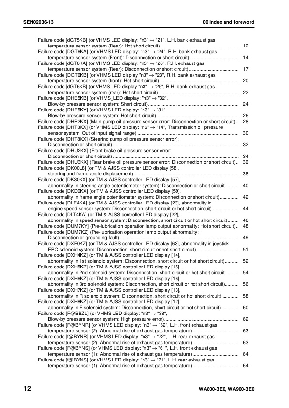
Failure code [DGT5KA] (or VHMS LED display: “n3” o “12”, L.H. bank exhaust gas temperature sensor system (Front): Disconnection or short circuit)
Failure code [dGT5KA] (or VHMS LED display: “n3” o “22”, L.H. bank exhaust gas temperature sensor system (Rear): Disconnection or short circuit)
Failure code [DGT5KB] (or VHMS LED display: “n3” o “11”, L.H. bank exhaust gas temperature sensor system (Front): Hot short circuit)
Failure code [dGT5KB] (or VHMS LED display: “n3” o “21”, L.H. bank exhaust gas temperature sensor system (Rear): Hot short circuit)
Failure code [DGT6KA] (or VHMS LED display: “n3” o “24”, R.H. bank exhaust gas temperature sensor system (Front): Disconnection or short circuit)
Failure code [dGT6KA] (or VHMS LED display: “n3” o “26”, R.H. exhaust gas temperature sensor system (Rear): Disconnection or short circuit)
Failure code [DGT6KB] (or VHMS LED display “n3” o “23”, R.H. bank exhaust gas temperature sensor system (front): Hot short circuit)
Failure code [dGT6KB] (or VHMS LED display “n3” o “25”, R.H. bank exhaust gas temperature sensor system (rear): Hot short circuit)
Failure code [DHE5KB] (or VHMS_LED display: “n3” o “32”, Blow-by pressure sensor system: Short circuit)
Failure code [DHE5KY] (or VHMS LED display: “n3” o “31”, Blow-by pressure sensor system: Hot short circuit)
Failure code [DHP2KX] (Main pump oil pressure sensor error: Disconnection or short circuit)
Failure code [DHT3KX] (or VHMS LED display: “n6” o “14”, Transmission oil pressure sensor system: Out of input signal range)
Failure code [DHT8KX] (Steering pump oil pressure sensor error): Disconnection or short circuit)
Failure code [DHU2KX] (Front brake oil pressure sensor error: Disconnection or short circuit)
Failure code [DHU3KX] (Rear brake oil pressure sensor error: Disconnection or short circuit)
Failure code [DK00L8] (or TM & AJSS controller LED display [58], steering and frame angle displacement)
Failure code [DK30KX] (or TM & AJSS controller LED display [57], abnormality in steering angle potentiometer system): Disconnection or short circuit)
Failure code [DKD0KX] (or TM & AJSS controller LED display [59], abnormality in frame angle potentiometer system: Disconnection or short circuit)
Failure code [DLE4KA] (or TM & AJSS controller LED display [23], abnormality in engine speed sensor system: Disconnection, short circuit or hot short circuit)
Failure code [DLT4KA] (or TM & AJSS controller LED display [22], abnormality in speed sensor system: Disconnection, short circuit or hot short circuit)
Failure code [DUM7KY] (Pre-lubrication operation lamp output abnormality: Hot short circuit)
Failure code [DUM7KZ] (Pre-lubrication operation lamp output abnormality: Disconnection or grounding fault)
Failure code [DXF0KZ] (or TM & AJSS controller LED display [63], abnormality in joystick EPC solenoid system: Disconnection, short circuit or hot short circuit)
Failure code [DXH4KZ] (or TM & AJSS controller LED display [14], abnormality in 1st solenoid system: Disconnection, short circuit or hot short circuit)
Failure code [DXH5KZ] (or TM & AJSS controller LED display [15], abnormality in 2nd solenoid system: Disconnection, short circuit or hot short circuit)
Failure code [DXH6KZ] (or TM & AJSS controller LED display [16], abnormality in 3rd solenoid system: Disconnection, short circuit or hot short circuit)
Failure code [DXH7KZ] (or TM & AJSS controller LED display [13], abnormality in R solenoid system: Disconnection, short circuit or hot short circuit)
Failure code [DXH8KZ] (or TM & AJSS controller LED display [12], abnormality in F solenoid system: Disconnection, short circuit or hot short circuit)
Failure code [F@BBZL] (or VHMS LED display: “n3” o “38”, Blow-by pressure sensor system: High pressure error)
Failure code [F@BYNR] (or VHMS LED display: “n3” o “62”, L.H. front exhaust gas temperature sensor (2): Abnormal rise of exhaust gas temperature)
Failure code [f@BYNR] (or VHMS LED display: “n3” o “72”, L.H. rear exhaust gas temperature sensor (2): Abnormal rise of exhaust gas temperature)
Failure code [F@BYNS] (or VHMS LED display: “n3” o “61”, L.H. front exhaust gas temperature sensor (1): Abnormal rise of exhaust gas temperature)
Failure code [f@BYNS] (or VHMS LED display: “n3” o “71”, L.H. rear exhaust gas temperature sensor (1): Abnormal rise of exhaust gas temperature)
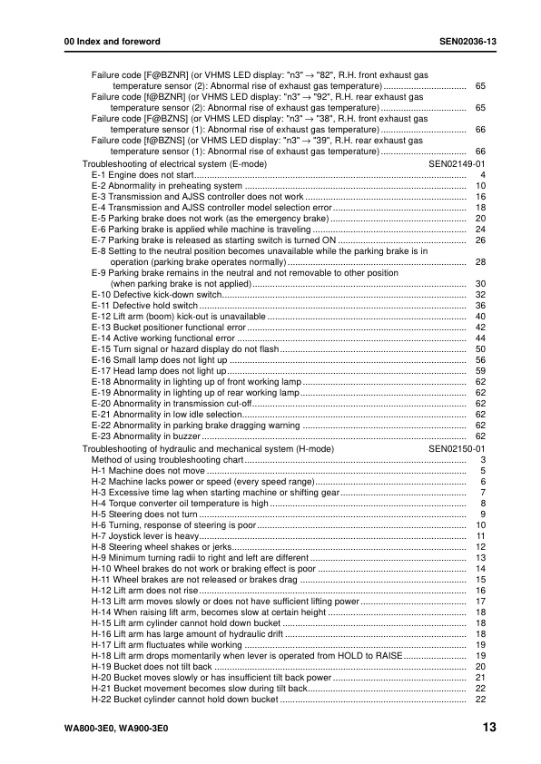
Failure code [F@BZNR] (or VHMS LED display: “n3” o “82”, R.H. front exhaust gas temperature sensor (2): Abnormal rise of exhaust gas temperature)
Failure code [f@BZNR] (or VHMS LED display: “n3” o “92”, R.H. rear exhaust gas temperature sensor (2): Abnormal rise of exhaust gas temperature)
Failure code [F@BZNS] (or VHMS LED display: “n3” o “38”, R.H. front exhaust gas temperature sensor (1): Abnormal rise of exhaust gas temperature)
Failure code [f@BZNS] (or VHMS LED display: “n3” o “39”, R.H. rear exhaust gas temperature sensor (1): Abnormal rise of exhaust gas temperature)
Troubleshooting of electrical system (E-mode)
E-1 Engine does not start
E-2 Abnormality in preheating system
E-3 Transmission and AJSS controller does not work
E-4 Transmission and AJSS controller model selection error
E-5 Parking brake does not work (as the emergency brake)
E-6 Parking brake is applied while machine is traveling
E-7 Parking brake is released as starting switch is turned ON
E-8 Setting to the neutral position becomes unavailable while the parking brake is in operation (parking brake operates normally)
E-9 Parking brake remains in the neutral and not removable to other position (when parking brake is not applied)
E-10 Defective kick-down switch
E-11 Defective hold switch
E-12 Lift arm (boom) kick-out is unavailable
E-13 Bucket positioner functional error
E-14 Active working functional error
E-15 Turn signal or hazard display do not flash
E-16 Small lamp does not light up
E-17 Head lamp does not light up
E-18 Abnormality in lighting up of front working lamp
E-19 Abnormality in lighting up of rear working lamp
E-20 Abnormality in transmission cut-off
E-21 Abnormality in low idle selection
E-22 Abnormality in parking brake dragging warning
E-23 Abnormality in buzzer
Troubleshooting of hydraulic and mechanical system (H-mode)
Method of using troubleshooting chart
H-1 Machine does not move
H-2 Machine lacks power or speed (every speed range)
H-3 Excessive time lag when starting machine or shifting gear
H-4 Torque converter oil temperature is high
H-5 Steering does not turn
H-6 Turning, response of steering is poor
H-7 Joystick lever is heavy
H-8 Steering wheel shakes or jerks
H-9 Minimum turning radii to right and left are different
H-10 Wheel brakes do not work or braking effect is poor
H-11 Wheel brakes are not released or brakes drag
H-12 Lift arm does not rise
H-13 Lift arm moves slowly or does not have sufficient lifting power
H-14 When raising lift arm, becomes slow at certain height
H-15 Lift arm cylinder cannot hold down bucket
H-16 Lift arm has large amount of hydraulic drift
H-17 Lift arm fluctuates while working
H-18 Lift arm drops momentarily when lever is operated from HOLD to RAISE
H-19 Bucket does not tilt back
H-20 Bucket moves slowly or has insufficient tilt back power
H-21 Bucket movement becomes slow during tilt back
H-22 Bucket cylinder cannot hold down bucket
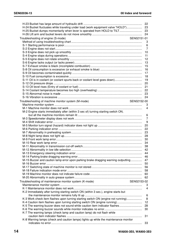
H-23 Bucket has large amount of hydraulic drift
H-24 Bucket fluctuates while traveling under load (work equipment valve “HOLD”)
H-25 Bucket dumps momentarily when lever is operated from HOLD to TILT
H-26 Lift arm and bucket levers do not move smoothly
Troubleshooting of engine (S-mode)
Method of using troubleshooting chart
S-1 Starting performance is poor
S-2 Engine does not start
S-3 Engine does not pick up smoothly
S-4 Engine stops during operations
S-5 Engine does not rotate smoothly
S-6 Engine lacks output (or lacks power)
S-7 Exhaust smoke is black (incomplete combustion)
S-8 Oil consumption is excessive (or exhaust smoke is blue)
S-9 Oil becomes contaminated quickly
S-10 Fuel consumption is excessive
S-11 Oil is in coolant (or coolant spurts back or coolant level goes down)
S-12 Oil pressure drops
S-13 Oil level rises (Entry of coolant or fuel)
S-14 Coolant temperature becomes too high (overheating)
S-15 Abnormal noise is made
S-16 Vibration is excessive
Troubleshooting of machine monitor system (M-mode)
Machine monitor system
M-1 Machine monitor does not work
M-2 Engine starts immediately after (within 3 sec of) turning starting switch ON, but all the machine monitors remain lit
M-3 Speedometer display does not work
M-4 Shift indicator error
M-5 Monitor turn signal (hazard) indicator does not light up
M-6 Parking indication error
M-7 Abnormality in preheating system
M-8 Night lamp does not light up
M-9 Front work lamp error
M-10 Rear work lamp error
M-11 Abnormality in transmission cut-off switch
M-12 Abnormality in low idle selection
M-13 Emergency steering indication error
M-14 Parking brake dragging warning error
M-15 Buzzer and caution lamp error upon parking brake dragging warning outputting
M-16 Buzzer error
M-17 Switching state of machine monitor is not stored
M-18 Failure indication mode error
M-19 Machine monitor does not indicate failure code
M-20 Abnormality in auto grease system
Troubleshooting of maintenance monitor system (K-mode)
Maintenance monitor system
K-1 Maintenance monitor does not work
K-2 Immediately after turning starting switch ON (within 3 sec.), engine starts but the maintenance monitor remains fully lit up
K-3 Work check item flashes upon turning starting switch ON (engine not running)
K-4 Caution item flashes upon turning starting switch ON (engine running)
K-5 The warning buzzer does not sound while caution item indicator flashes
K-6 The warning buzzer sounds while monitor indicates no error
K-7 The warning lamps (check lamp and caution lamp) do not flash while caution item indicator flashes
K-8 Warning lamps (check and caution lamps) lights up while the maintenance monitor indicates no error
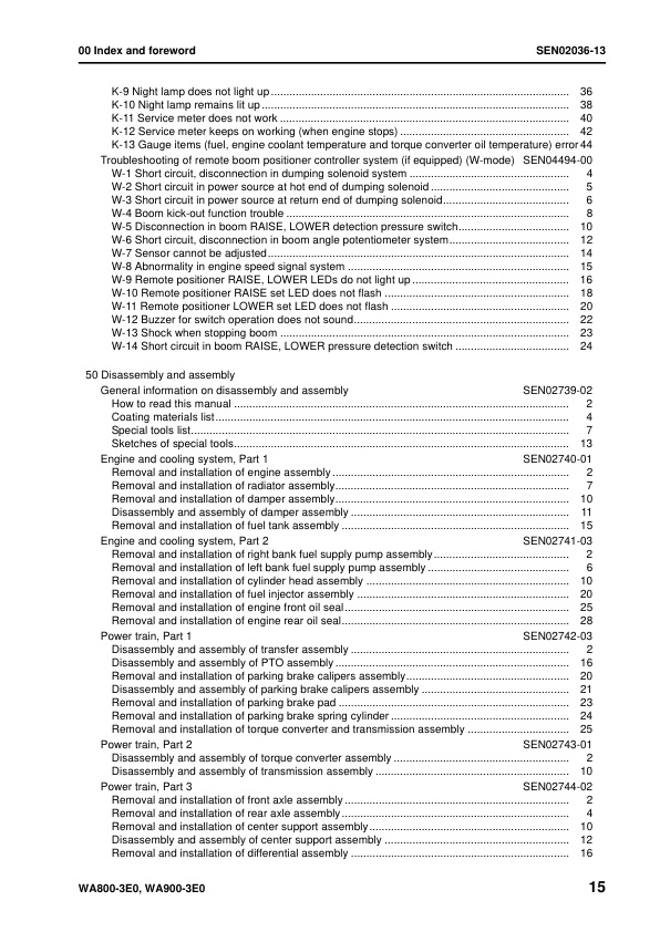
K-9 Night lamp does not light up
K-10 Night lamp remains lit up
K-11 Service meter does not work
K-12 Service meter keeps on working (when engine stops)
K-13 Gauge items (fuel, engine coolant temperature and torque converter oil temperature) error
Troubleshooting of remote boom positioner controller system (if equipped) (W-mode)
W-1 Short circuit, disconnection in dumping solenoid system
W-2 Short circuit in power source at hot end of dumping solenoid
W-3 Short circuit in power source at return end of dumping solenoid
W-4 Boom kick-out function trouble
W-5 Disconnection in boom RAISE, LOWER detection pressure switch
W-6 Short circuit, disconnection in boom angle potentiometer system
W-7 Sensor cannot be adjusted
W-8 Abnormality in engine speed signal system
W-9 Remote positioner RAISE, LOWER LEDs do not light up
W-10 Remote positioner RAISE set LED does not flash
W-11 Remote positioner LOWER set LED does not flash
W-12 Buzzer for switch operation does not sound
W-13 Shock when stopping boom
W-14 Short circuit in boom RAISE, LOWER pressure detection switch
50 Disassembly and assembly
General information on disassembly and assembly
How to read this manual
Coating materials list
Special tools list
Sketches of special tools
Engine and cooling system, Part 1
Removal and installation of engine assembly
Removal and installation of radiator assembly
Removal and installation of damper assembly
Disassembly and assembly of damper assembly
Removal and installation of fuel tank assembly
Engine and cooling system, Part 2
Removal and installation of right bank fuel supply pump assembly
Removal and installation of left bank fuel supply pump assembly
Removal and installation of cylinder head assembly
Removal and installation of fuel injector assembly
Removal and installation of engine front oil seal
Removal and installation of engine rear oil seal
Power train, Part 1
Disassembly and assembly of transfer assembly
Disassembly and assembly of PTO assembly
Removal and installation of parking brake calipers assembly
Disassembly and assembly of parking brake calipers assembly
Removal and installation of parking brake pad
Removal and installation of parking brake spring cylinder
Removal and installation of torque converter and transmission assembly
Power train, Part 2
Disassembly and assembly of torque converter assembly
Disassembly and assembly of transmission assembly
Power train, Part 3
Removal and installation of front axle assembly
Removal and installation of rear axle assembly
Removal and installation of center support assembly
Disassembly and assembly of center support assembly
Removal and installation of differential assembly
Disassembly and assembly of differential assembly
Disassembly and assembly of final drive assembly
Brake system
Removal and installation of brake assembly
Disassembly and assembly of brake assembly
Removal and installation of left brake valve assembly
Removal and installation of right brake valve assembly
Disassembly and assembly of accumulator charge valve
Disassembly and assembly of slack adjuster
Undercarriage and frame
Removal and installation of center hinge pin
Removal and installation of counterweight assembly
Hydraulic system
Removal and installation of hydraulic tank and filter case assembly
Removal and installation of hydraulic pump assembly
Removal and installation of work equipment control valve assembly
Disassembly and assembly of work equipment control valve assembly
Disassembly and assembly of PPC valve assembly
Removal and installation of steering valve assembly
Removal and installation of diverter valve assembly
Disassembly and assembly of diverter valve assembly
Removal and installation of Orbit- roll assembly
Removal of steering stop valve
Installtion of steering stop valve
Disassembly and assembly of hydraulic cylinder assembly
Work equipment
Removal and installation of work equipment assembly
Replacement of boom front bushing
Cab and its attachments
Removal and installation of operator cab assembly
Removal and installation of floor frame assembly
Disassembly and assembly of operator’s seat assembly
Removal and installation of AJSS lever switch assembly
Electrical system
Removal and installation of engine controller assembly
Removal and installation of transmission and steering controller assembly
Removal and installation of main monitor assembly
Removal and installation of air conditioner unit assembly
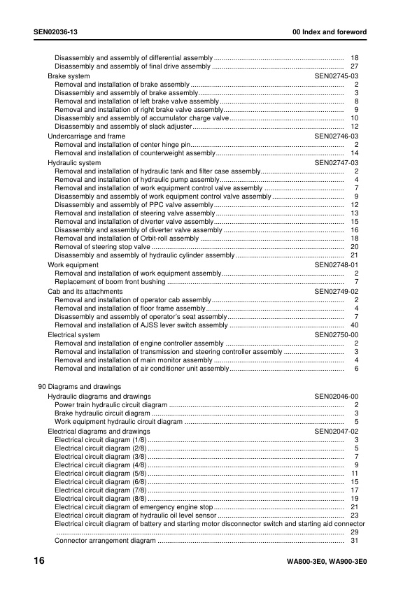
90 Diagrams and drawings
Hydraulic diagrams and drawings
Power train hydraulic circuit diagram
Brake hydraulic circuit diagram
Work equipment hydraulic circuit diagram
Electrical diagrams and drawings
Electrical circuit diagram (1/8)
Electrical circuit diagram (2/8)
Electrical circuit diagram (3/8)
Electrical circuit diagram (4/8)
Electrical circuit diagram (5/8)
Electrical circuit diagram (5/8)
Electrical circuit diagram (6/8)
Electrical circuit diagram (7/8)
Electrical circuit diagram (8/8)
Electrical circuit diagram of emergency engine stop
Electrical circuit diagram of hydraulic oil level sensor
Electrical circuit diagram for KAL (1/2)
Electrical circuit diagram for KAL (2/2)
Electrical circuit diagram of battery and starting motor disconnector switch and starting aid connector
Electrical circuit diagram for bucket tilt limitter (If equipped)
Connector arrangement diagram
There are no reviews yet.