Kubota KX121-3, KX161-3 Excavator 97899-60550 (Preview)
WSM_KX-121-3_161-3
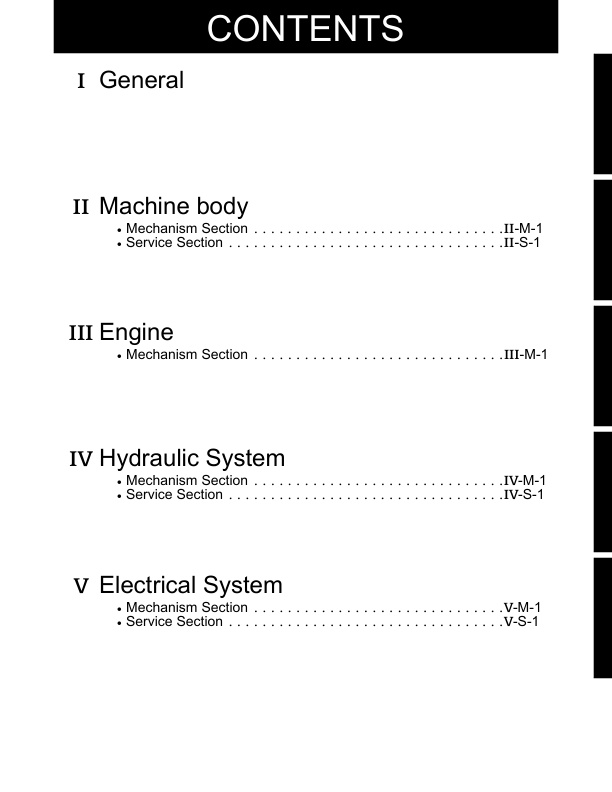
– CONTENTS
– I. General
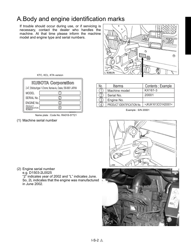
— A. Body and engine identification marks
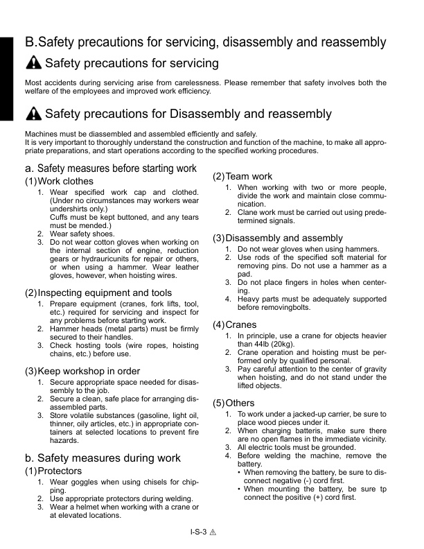
— B. Safety precautions for servicing, disassembly and reassembly
— a. Safety measures before starting work
—- (1) Work clothes
—- (2) Inspecting equipment and tools
—- (3) Keep workshop in order
— b. Safety measures during work
—- (1) Protectors
—- (2) Team work
—- (3) Disassembly and assembly
—- (4) Cranes
—- (5) Others
— c. Preparation for disassembly
—- (1) Cleaning
—- (2) Acceptance inspection
—- (3) Equipment and tools
— d. Precautions for disassembly and reassembly
—- (1) Disassembly
—- (2) Reassembly
— C. IMPORTANT SAFTY PROCESS AND CRITICAL FUNCTIONAL PROCESS
— a. Essential Adhesives
— b. Important Safety Process .
— c. Important Critical Functional Process .
— D. IMPORTANT INSPECTION ITEMS AFTER REASSEMBLING
— a Operate the Machine and check for Unusual Noise and Vibrations.
— b Make Sure the Safety decals and Wireharness Clamps are in their Specified Positions.
— c With the Machine Front in a Specified Posture, Check the Amount of Hydrauric Oil
— E. SERVICING FUNDAMENTALS
— a. Items for Servicing
— b. O-ring, Oil seal, Circlip and Roll Pin
— c. Piping
—- (1) General precautions
—- (2) Hydraulic hose
—- (3) Precautions in tightening the bolts and nuts
—- (4) Hose screw
—- Metric Size Hose
—- (5) Joint bodies
—- (6) Tightening torque table for hose clamp (Screw type)
—- (7) Nuts for piping
—- (8) Tightening torque of bolts and nuts
—- (9) Types and materials of bolts and nuts
—- (10) Washer-equipped elbow
—- Machine Quality Specifications
—- KX121-3, 161-3 : KTC, KCL, KTA Version
— F. Maintenance intervals
— a. KTC, KCL, KTA-version
— b. EU-version
— c. Hydraulic Oil Check for machines with Hydraulic Breakers
— G. Water and oil quantity
— H. Recommended oil
— I. Filters
— J. Compatibility Table of main components between U45-3. and KX121-3, 161-3
– II. Machine body(Mechanism section)
— A. Product Feature
— a. A New Load Sensing System.
—- Upgraded basic performance -work efficiency
— b. Low Operating Cost, Easy To Service
— c. Built For Tough Work, Not Tough On The Operator.
— B. Standard equipment
— C. Machine specifications
— a. KX121-3 EU-version
— b. KX161-3 EU-version
— c. KX121-3 KTC, KCL, KTA-version
— D. Component interchangeability
— a. Bucket interchangeability
— b. Arm
— E. Machine structure
— a. Front attachment : KX121-3, EU-version
— b. Seat & control box
— c. Control linkage
— d. Engine mount : KX161-3
— e. Undercarriage : KX121-3
— f. Rubber track
— g. Iron track
— h. Track conversion : KX121-3
—- Between rubber track and iron track
– II. Machine body(Service section)
— A. Specifications
— a. Machine Weight
—- (1) KE, KDG, KUK version
—- (2) KTC, KCL, KTA version
— b. Machine specifications
—- (1) KE, KDG, KUK version
—- (2) KTC, KCL, KTA version
— c. Lever stroke and operating force
—- (1) KE, KDG, KUK version
—- (2) KTC, KCL, KTA version
— d. Dimensions of Parts
—- (1) Front pins
—- (2) Bucket
—- (3) Rubber crawler
—- (4) Iron crawler
—- (5) Track toller, idler, sprocket
—- (6) Dozer
—- (7) Parts weight
—- (8) Water and Oil Quantity
— B. Front attachment
— a. Parts designation
— b. Exchange of bucket (Kubota Japan Bucket)
— c. Exchange of bucket teeth and side cutter
— d. Installing direction of dust seal
— e. Installation of thrust collar on the swing bracket
— f. Installing pin, bush and shim (1):KX121-3, KX161-3
— g. Installing pin, bush and shim (2):KX121-3, KX161-3
— h. Installing pin, bush and shim of bucket:KX121-3, KX161-3
— i. Installing local bucket : KX121-3, KX161-3
— j. Greasing points
— k. Front hoses and clamps : KX121-3, KX161-3
— f’. Installing pin, bush and shim (1):KX161-3 KTC, KCL, KTA
— g’. Installing pin, bush and shim (2):KX161-3, KTC, KCL, KTA
— h’. Installing pin, bush and shim of bucket:KX161-3, KTC, KCL, KTA
— l. Installing direction of fixing pin bolts : KX121-3
— C. Upper Structure
— a. Swivel bearing
— b. Pilot control lever : KX121-3, KX161-3
— c. Traveling lever : KX121-3, KX161-3
— d. Traveling lever adjustment : KX121-3, KX161-3
— e. Traveling lever lock : KX121-3, KX161-3
—- Adjusting the lever’s neutral position
— f. Accelarator lever : KX121-3, KX161-3
—- (1) KE, KUK, KDG version
—- (2) KTC, KCL, KTA version
— g. Dozer lever : KX121-3, KX161-3
—- (1) EU version
—- (2) KTC, KCL, KTA version
—- (3) KX161-3 : KTC, KCL, KTA version
— h. TPSS lever : KTC, KCL, KTA-version : KX121-3
— i. Swing & SP pedal : KX121-3, KX161-3
— j. Control valve links : KX121-3, KX161-3
— k. Limit switch installation : KX121-3, KX161-3
— l. Control stand
— m. Control stand : KX121-3
— n. Installing weight : KX121-3, KX161-3
— o. Installing covers : KX121-3, KX161-3
— D. Cab installation : KTC, KCL, KTA-version
— a. Mounting bolt
— b. Seal rubber
— c. Wiper : KTC, KCL, KTA-version
— d. Heater hose : KTC, KCL, KTA-version
— e. Wire harness : KTC, KCL, KTA-version
— f. Cab glass replacement procedure
—- (1) Application Procedure if SIKAFLEX (ULTRA-FAST)
—- (2) ULTRA-FAST application manual
—- (3) 255 EXTRA application manual
—- (4) H-rubber replacement procedure
—- (5) Broken glass repairing procedure (for adhered glass KX-2 Series made by KBT)
— g. Defroster hose : KTC, KCL, KTA
— h. Defroster hose : EU
— E. Under carriage
— a. Track tension device : KX121-3, 161-3
— b. Track sag distance
— c. Crawler installation
— d. Track Roller and Upper Roller installation
– III. Engine
— A. Specifications & features
— a. Technical data : KX121-3, KX161-3
— b. Performance curve
— c. Features
— d. Structure and function
—- (1) Fuel injection pump
—- (2) Coupling flange
—- (3) Fuel filter
—- (4) Air filter
—- (5) Thermostat
— B. Engine mounting procedure : KX121-3
— a. Engine mount
— b. Air cleaner : KX121-3, KX161-3
— c. Radiator : KX121-3, KX161-3
— d. Muffler : KX121-3, KX161-3
— e. Pump coupling
— f. Fuel tank installation : KX121-3, KX161-3
— g. Fuel tank cushion : KX121-3, KX161-3
— h. Fuel hoses : KX121-3, KX161-3
— i. Accel cable and meter cable
— C. 03-M series Engine WSM
– IV. Hydraulic system(Mechanism section)
— A. Features of hydraulic system
— EEE hydraulic systtem
— (1)Three big features
— (2) New Hydraulic System Features
— (3) Component of new hydraulic system
— (4) Circuit comparison between New Hydraulic System and conventional systems
— (5) Feature 1. High Efficiency
— (6) Feature 2. Easy operation
— (7) Feature 3. Economy
— B. Hydraulic system specifications
— C. Main pump
— a. Structure & performance curve
— b. Operating principle
—- (1) Variable displacement pump
—- (2) Power control
—- (3) Load sensing control
—- (4) Gain control
—- (5) Standby Flow
— D. Control valve
— a. Specifications
— b. General view of control valve
— c. Control valve circuit diagram
— d. Operating principle
—- (1) Unload valve
—- (2) High-pressure selector valve
—- (3) Pressure compensating valve
—- (4) Boom anti-drift valve
— e. Automatic air bleeding in hydraulic pilot section
—- (1) When the spool of the control valve is at neutral position.
—- (2) When the spool of the control pilot valve is moved in full stroke.
— f. Relief valve/Anti-cavitation valve
— E. Pilot valve
— a. Structure & specifications
— b. Pilot valve control diagram
—- (1) KE, KDG, KUK version
—- (2) KTC, KCL, KTA version
— F. Swivel motor
— a. Structure & specifications
— b. Function of negative brake
—- (1) Negative brake function(Unload condition)
—- (2) Negative brake release(On-load condition)
— c. Function of valve section
—- (1)Make-up valve
—- (2)Function of shockless valve
—- (3) Relief valve
—- (4) Shockless piston
—- (5) Make-up poppet
— G. Rotary joint (Swivel joint)
— H. Travel motor
— a. Structure & specification
— b. Operation of piston motor
— c. Function of anti-cavitation valve
—- (1) Construction
—- (2) Circuit behavior
— I. Hydraulic circuit diagram
— a. KX121-3 European – version
— b. KX161-3 European – version
— c. KX121-3 KTC, KCL, KTA – version
— d. Hydraulic components layout
— e. KX161-3 European-version
— f. KX161-3 KTC, KCL, KTA-version
– IV. Hydraulic system(Service section)
— A. Troubleshooting
— a. Case – Study : Abnormal speed
— b. Case – Study : The power is weak.
— c. Case – Study : Poor Manipulation and Abnormal Operation
— c. Case – Study : Poor Manipulation and Abnormal Operation
— d. LS control system troubleshooting
— e. Pump component trouble causes and remedy
— f. Control valve component troubleshooting
— g. Travel motor component troubleshooting
— B.Specifications
— a. Relief valve pressure setting
— b. Pump
— c. Load sensing control system data
— d. Cylinder
— e. Swivel Performance
— f. Traveling Performance
— C.Testing
— a. Testing Instruments & special tools
— b. Precautions in handling the pump
— c. Pilot pressure
— d. Main relief valve
— e. Unload valve
— f. Overload relief valve
— g. Swivel brake valve pressure
— h. Measuring the main pump Max. flow rate
— i. Measuring the main pump’s stand-by flow rate
— j. LS control pressure
— k. Traveling motor drain amount
— l. Swivel motor drain amount
— m.Swivel motor block performance
— n. Traveling motor block performance
— o. Operating speed
— p. Straight travel performance
— q. Cylinder natural fall amount
— r. Control and Traveling lever operating force
— s. Lever stroke
— D. Disassembling and Assembling
— a. Coupling flange
— b. Pump:KX121-3, KX161-3
— c. Control valve
— d. Pilot valve
— e. Swivel motor
— f. Wheel motor : KX121-3, 161-3
— g. Rotary joint : KX121-3, 161-3
— h. Cylinder (KE, KDG, KUK version)
— h. Cylinder (KTC, KCL, KTA version)
— i. Other hydraulic device
— j. Hoses
– V. Electrical system(Mechanism section)
— A. Components, harness layout & coupler
— A. Components, harness layout & coupler : KX161-3 AI-version
— B. Circuit diagram
— a. Electric Circuit Diagram: KX121-3, KX161-3
— b. Functional Electric Circuit Diagram : KX121-3, KX161-3
— c. Cab Electric Diagram : KX121-3, KX161-3
—- KTC, KCL, KTA-version
— d. Cab Electric Diagram : KX121-3
—- EU-version
— e. Electric Circuit Diagram : KX161-3 AI-version
— f. Electric Wiring Diagram : KX161-3 AI-version
— C. Function of main circuit
— a. Battery circuit (Non-AI-version)
— b. Safety Relay circuit (Automatic release function) Non-AI-version
—- (1) Operation
—- (2) Precaution
—- (3) Function chart of auto release controller
— c. Auto glow circuit (Non-AI-version)
—- (1) Function
— d. Fuel control circuit (Non-AI, AI-version)
—- (1) Function
—- (2)Engine stop solenoid (Non-AI, AI-version)
— e. Engine oil pressure sensor circuit (Non-AI, AI-version)
— f. Horn circuit (Non-AI, AI-version)
—- (1)Structure
—- (2)Function
—- (3) Current flow
—- (4) Horn circuit
— g. Cab & Working lamp circuit (Non-AI, AI-version)
— h. Meter panel (Non-AI-version)
— i. Heater circuit (Non-AI, AI-version)
— j. Travel hi-speed control circuit (Non-AI, AI-version)
— k. Auto idle control system (AI-version)
—- (1)Purpose
—- (2)Auto idle function mechanism
—- (3)AI function layout
—- (4) Behavior when the control lever is returned to neutral
—- (5) Behavior when the control lever is operated:
—- (6) AI motor normal-turn circuit
—- (7) AI motor reverse-turn circuit
— l. Battery direct line (AI-version)
— m. Starter lock relay & auto release relay (AI-version)
—- (1) Safety start system
—- (2) Auto release function (AI- version)
— n. Self holding relay circuit (AI-version)
— o. Water temp. sensor circuit (AI-version)
— p. Meter panel (AI-version)
— q. AI controller unit (AI-version)
— D. Structure and function of main components
— a. Key switch (Engine starter switch)
— b. Water temp. sensor & gauge
— c. Fuel gauge
— d. Safty lever lock switch, travel hi-low pedal switch
— e. Relay
— f. Engine speed sensor
— g. Governor sensor
— h. Accel sensor (Electric accelerator)
— i. AI pressure switch
— j. Foundamentals
— k. Measurement
—- (1) Measurement of current
—- (2) Measurement of voltage
—- (3) Measurement of resistance
— l. Introduction of semiconductor
—- (1) Semiconductor
—- (2) Genuine semiconductor
—- (3) Impurity semiconductor
—- (4) Diode
—- (5) Transistor
—- (6) Thyristor (SCR)
— m. Introduction of magnetism
—- (1) Magnet & magnetism
—- (2) Magnetic line of force and magnetic field
—- (3) Magnetic action of electricity
— n. Introduction of starter motor
—- (1) Operating Principle
—- (2) Principle of motor, Fleming’s left hand rule
—- (3) Type of starter
— o. Introduction of generator, alternator
—- (1) Outline of Electric Generator and Charging System
—- (2) Principle of Alternator
—- (3) Small Alternator with IC Regulator
– V. Electrical system(Service section)
— A. Wire harness installation
— a. Precautions
— b. Engine earth, starter switch
— c. Main harness
— d. Control box
— e. Engine harness
— f. Front harness
— g. AI motor installation : AI-version
— h. Control box : AI-version
— i. Main harness : AI-version
— B. Troubleshooting
— a. General
—- (1) How to diagnose
—- (2) INSPECTION OF HARNESS CONNECTOR
—- (3) Inspection
—- (4) INSPECTION INSTRUMENTS
—- (5) CHECKING SWITCHES
—- (6) Checking fuses
—- (7) Solenoid test method
—- (8) Checking relays
—- (9) Checking cables and wires
—- (10) HANDLING ON-VEHICLE BATTERY
— b. Troubleshooting flow chart
—- (1) Starter motor failure to turn on
—- (2) Auto release malfunction
—- (3) Electronic accelerator failure
—- (4) Auto glow failure
—- (5) AI system failure
— c. Front attachment
—- (1) Working lamp failure
—- (2) Safety lever lock circuit malfunction
— d. Engine electrical system
—- (1) Engine oil pressure failure
—- (2) Water temp. sensor circuit malfunction
—- (3) Fuel sensor circuit
—- (4) Engine stop solenoid
—- (5) Charging system malfunction
—- (6) Auto glow controller
—- (7) Auto release controller
— e. Auto idle system
—- (1) Troubleshooting outline
—- (2) AI pressure switch test method
—- (3) Governer sensor test method
—- (4) AI motor test method
—- (5) Engine speed sensor
—- (6) Auto glow circuit
— f. AI version: AI controller (built-in microcomputer) Cases of trouble diagnosis with circuit tester
—- (1) “Water temperature sensor” line in trouble
—- (2) Other circuitry layouts and their trouble diagnosis
— g. Cases of trouble diagnosis with circuit tester
— h. Auto Idle(AI) version: Trouble diagnosis with lamp
—- (1) General
—- (2) Display and identification of errors in operating mode
—- (3) Entering the service mode
—- (4) Working on the 6 menus in the service mode
—- (5) Example:Alternation of engine idling speed
—- (6) Working on the 3 menus in the service mode
—- (7) Working on the AI motor drive menus in the service mode
—- (8) Entering the setup mode
—- (9) Lamp-identified fail symptoms, trouble spots and possible causes
— C. Electrical equipment specifications
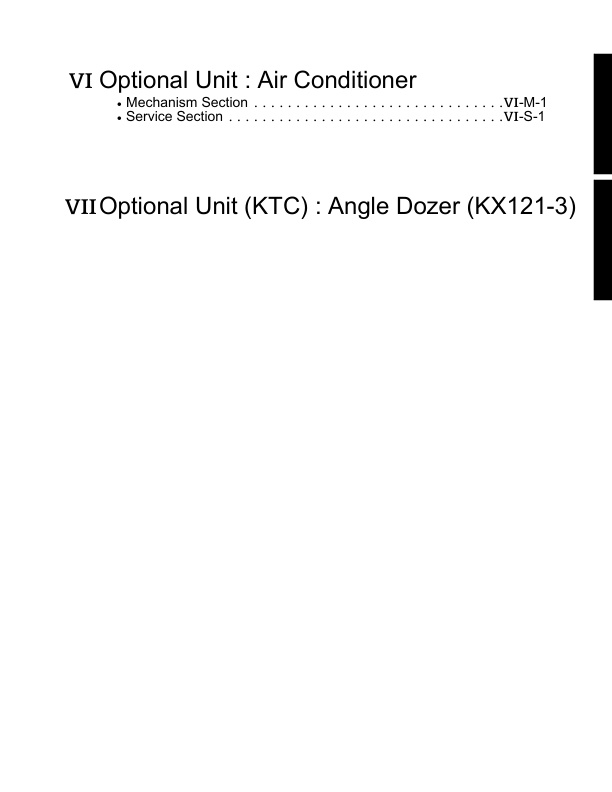
– VI. Optional Unit : Air Conditioner(Mechanism Section)
— A. Air Condition System
— a. Introduction of air conditioner
—- (1) Principle of Air Conditioner
—- (2) Change of State of Refrigerant
—- (3) Function and Construction
—- (4) Refrigerant Cycle
— b. Components and location
—- (1) Air conditioner & accessory assy
—- (2) Layout of A/C components : AI-version
—- (3) Layout of A/C components : Non AI-version
— c. A/C system, electric circuit diagram
—- (1) Key-Off condition
—- (2) Key-ON(AC) condition
—- (3) A/C electric circuit diagram(DENSO A/C)
—- (4) Key-Off condition
—- (5) Key-ON (A/C) Conditions
—- (6) Key-ON (A/C) + A/C SW-ON Condition
—- (7) Key-ON (A/C) + A/C SW-ON + Blower SW-Low Condition
—- (8) Key-ON (A/C) + A/C SW-ON + Blower SW-Low + thrmostat-OFF Condition
— B. Function and structure
— a. Compressor
—- (1) Outline of sliding-vane type compressor (SV07 type) : KX121-3, 161-3
—- (2) Feature
—- (3) Main specifications
—- (4) Structure & Function
—- (7) Oil Replenishment upon Function Part Replacement (for the HFC134a System)
— b. High pressure relief valve
— c. Magnetic Clutch
—- (1) Principle
—- (2) Magnetic Clutch
—- (3) Operation
— d. Condenser
—- (1) Description
—- (2) Type of Condenser
— e. Receiver
— f. Dual Pressure Switch
—- (1) Location & structure
—- (2) When the Pressure is Abnormally High
—- (3) When the Pressure is Abnormally Low
— g. Air Conditioner Unit
—- (1) Outline
—- (2) Expansion Valve
—- (3) Evaporator
—- (4) Heater Core
—- (5) Water Valve
—- (6) Air filter
—- (7) A/C Blower
—- (8) Gas Type Thermostat
—- (9) A/C blower resistor
— h. Refrigerant
—- (1) Refrigerant R134a
—- (2) Refrigerant Properties
— C. Electrical System
— a. Electrical Circuit
— c. Air Conditioner Blower Switch
— d. Dual Pressure Switch
—- (1) Pressure Switch (Dual Type)
— e. Thermostat
— f. Control Panel
— g. Air Flow
— D. Technical Terms
— a. Heat
—- (1) Specific Heat
— b. Temperature
—- (1) Temperature Scales
—- (2) Wet Bulb and Dry Bulb Thermometers
—- (3) Dew Point Temperature
— c. Humidity
—- (1) What is Humidity ?
—- (2) Relative Humidity
—- (3) Absolute Humidity
—- (4) Check Performance of Air Conditioning System
— d. Pressure
—- (1) Atmospheric Pressure
—- (2) Absolute Pressure
— e. Change of State
—- (1) Stage Change of Water
—- (2) Sensible Heat and Latent Heat
—- (3) Three States of Matter
— f. What is a Heater?
—- (1) Principle
—- (2) Temperature Control
— g. Principle of Cooling
—- (1) Basic Theory of Cooling
—- (2) Refrigerant
— h. Principle of Air Conditioning
—- (1) Expansion and Evaporation
—- (2) How to Condense Gaseous HFC134a into Liquid
—- (3) Condensing of the Gaseous HFC134a
— i Refrigeration Cycle
— j. Practical Control of Air Conditioner
—- (1) Concept of control
—- (2) Principle of control
— k. Mollier Diagram
— l. Basic Operation of Cooling Cycle
— m. Calculation of Refrigeration Capacity and Power from Mollier Diagram
— n. Calculation of Flow of Circulating Refrigerant
— o. Theoretical Performance (Sample Calculation)
—- (1) Compressor out put ; L
—- (2) Evaporator capacity Qer ;
—- (3) Condenser capacity Qco ;
—- (4) Basically,
—- (5) Coefficient of Performance ;
—- (6) Relevant diagram
– VI. Optional Unit : Air Conditioner(Service Section)
— A. Troubleshooting
— a. Visual and Audible Inspection
— b. Components
— c. Diagnosis flow chart
— d. Troubleshooting from Problem Symptoms (Except Refrigeration Cycle Troubles)
— B. Servicing Specifications
— a. Specifications of A/C system and components
— b. Performance Specifications
— c. Adjustment and Testing
— d. Ambient Temperature vs Normal High-Low Pressure Range
— e. Tightening Torques
— C.Regular Check and Service Points
— a. Maintenance interval ; Air conditioner
— b. Regular Service Points
— D. Precautions at Repairing Refrigerant Cycle
— E. Precaution for Installation and Maintenance
— F. Checking and Charging Refrigerant Cycle
— a. Handling Of Service Tools
—- (1) Manifold Gauge Set
—- (2) Refrigerant Charging Hose
—- (3) Vacuum Pump Adaptor
—- (4) Electric Gas Leak Tester
—- (5) Can Tap Valve
—- (6) T-joint
—- (7) R134a Refrigerant Recovery and Recycling Machine
—- (8) Special tools
— b. Checking with Manifold Gauge
— c. Discharging, Evacuating and Charging
—- (1) Discharging the System
—- (2) Evacuating the System
—- (3) Charging the System
—- Charging an Empty or Partially Charged System (Vapor)
—- (4) Checking Charge Refrigerant Amount
—- (5) Charging procedure of refrigerant (Summary)
— G. Main Components Servicing
— a. Compressor
—- (1) Checking
—- (2) Disassembling and reassembling
—- (3) Compressor dismounting
—- (4) Hub Plate
—- (5) Rotor
—- (6) Stator
—- (7) Adjustment of Air-gap
—- (8) Compressor installation
—- (9) V-belt tension
—- (10) Engine bracket 1, A/C
—- (11) Relief valve
— b. Condenser and Receiver
—- (1) Parts location
—- (2) Installation of condenser and receiver
— c. Air conditioner unit
—- 1. Mounting proceduse
—- 2. Location of steps
—- 3. Dismounting steps
— d. Electrical System Components
—- (1) A/C Blower Relay and Compressor Relay
—- (2) Relay specs (at 20˚C)
—- (3) A/C Blower Switch
—- (4) A/C Blower Motor Test
—- (5) A/C cooler switch
—- (6) A/C Blower Resistor
—- (7) Dual pressure switch
— e. Heater hose and control cable
—- (1) Parts location
—- (2) Water Valve Control Cable (White Tape)
—- (3) A/C switch
— f. Cooler hoses installation
—- (1) Handling the air-conditioner parts
—- (2) Cooler hose
—- (3) Gas charging
—- (4) Cooler hoses layout 1
—- Connection of cooler hoses
—- (5) Cooler hoses layout 2
—- (6) Cooler hoses layout 3
—- (7) Hoses Layout photos
— g. Duct cover installation
— h. Noise absorber and trims
— i. Labels
— j. Wire harness route
— k. Wireharness clamps for A/C version
— l. Parts identification of Air conditioner version
—- (1) Changes in the engine
—- (2) Changes in the radiator and oil cooler
—- (3) Changes in the frame (arch)
—- (4) Changes in the steps
—- (5) Changes in the right-side control
—- (6) Replacing the rubber mat
—- (7) Changes in the cabin
—- (8) Replacing the bonnet frame (R)
—- (9) Replacing the left bonnet (1)
—- (10) Replacing the bonnet cover assembly (1)
—- (11) Replacing the seat support cover
—- (12) Replacing the seat mount parts
—- (13) Replacing the wire harness
—- (14) Replacing the upper cover (R)
—- (15) Replacing the battery-related parts (Only for the KX121-3US without AI(Type: 95D31R –> 80D26R))
—- (16) Compressor
—- (17) Receiver and condenser
—- (18) Air conditioner unit
—- (19) A/C switch and heater valve
—- (20) Duct
—- (21) Seat support
—- (22) Step plate
—- (23) Bonnet, left
– VII. Optional Unit (KTC) : Angle Dozer (KX121-3)
— A. Specifications
— B. Machine Quality Specifications
— C. Lubrication point of angle dozer
— D. Dozer lever
— a. Dozer angle operation
— b. Dozer lever, angle
— E. Control valve
— a. Specifications
— b. General view of control valve
— c. Control valve circuit diagram
— d. Angle section
— e. Adaptor installation
— F. Rotary joint
— a. Assembling of the rotary joint
— b. Adaptor installation
— c. Hose connection
— G. Under carriage
— a. Angle dozer
— H. Hydraulic Circuit
— a. KX121-3 Hydraulic Circuit (USA, Angle blade)


Reviews
There are no reviews yet.