New Holland E57C Mini Excavator 91770419 (Preview)
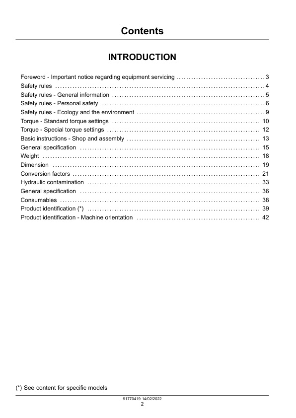
INTRODUCTION
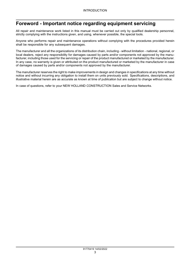
– Foreword – Important notice regarding equipment servicing
– Safety rules
— Personal safety
— FAILURE TO FOLLOW DANGER, WARNING, AND CAUTION MESSAGES COULD RESULT IN DEATH OR SERIOUS INJURY.
— Machine safety
— Information
– Safety rules – General information
— Cleaning
— Inspection
— Bearing
— Needle bearing
— Gear
— Oil seal, O-ring, gasket
— Shaft
— Service parts
— Lubricants (fuel, hydraulic oil)
– Safety rules – Personal safety
— Preliminary warnings to maintenance operation
— Personal Protective Equipment (PPE)
— Lifting operation
— Hydraulic system
— Battery
— Fluids
– Safety rules – Ecology and the environment
— Helpful hints
— Battery recycling
— Mandatory battery recycling
– Torque – Standard torque settings
— BOLT AND NUT
— Coarse thread
— Fine thread
— Pipe and hose (FLARE type)
— Pipe and hose (ORFS type)
— Fitting
– Torque – Special torque settings
– Basic instructions – Shop and assembly
— Shimming
— Rotating shaft seals
— O-ring seals
— Sealing compounds
— Spare parts
— Protecting the electronic and/or electrical systems during charging and welding
— NO TITLE
— Special tools
– General specification
— Engine
— Main pump (P1 / P2)
— Gear pump / Pilot pump (P3 / P4)
— Main control valve
— Swing motor
— Travel motor
— Cylinder
— Shoe
— Number of rollers and shoe on each side
– Weight
– Dimension
— Working range
– Conversion factors
— Unit conversion rate
— Length
— Area
— Volume
— NO TITLE
— Weight
— NO TITLE
— Pressure
— Torque
— Temperature
– Hydraulic contamination
– General specification
— Biodiesel usage in products
— Introduction to Fatty Acid Methyl Ester (FAME) biodiesel
— Diesel and biodiesel fuel specifications
— Biodiesel fuel usage conditions
— Storage
– Consumables
– Product identification
— Machine
— Engine
— ID label A
— Emission decal B
— Roll Over Protective Structure (ROPS)
— Component serial numbers
– Product identification – Machine orientation
Engine
– Engine and crankcase
— Engine
— Engine – Engine horse power
—- Performances
— Engine – Special tools
—- Measuring instruments
— Engine – Torque for general use
— Engine – Torque for special use
— Engine – Service limits
— Crankcase
— Crankcase – Service limits
— Engine
— Engine – Overview
—- Engine main components
—- Engine sensors
— Engine – Exploded view
— Engine – Dynamic description
—- Function of major engine components
—- Main electronic control components and features
— Engine – Identification
—- ID label (A)
—- Emission decal (B)
—- Description of model number
— Engine
— Engine – Check – Oil Consumption
— Engine – Service instruction – Components replacement
—- Processing the DPF regeneration after the parts replacement
—- Calculation of PM sediment amount in DPF
—- Processing after the ECU replacement (when it is impossible to inherit from the old ECU)
—- Required processing at the parts replacement
— Engine – Compression test
—- Standard compression pressure (reference value)
—- Engine speed and compression pressure (use for reference)
—- Measured value and troubleshooting
— Engine – Change fluid – Engine oil and oil filter
— Engine – Remove
— Engine – Disassemble
—- DISASSEMBLY OF CAMSHAFT AND TIMING COMPONENTS
—- Gears backlash check
—- Removal of timing gear case cover
—- Removal of timing gears
—- Removal of oil pan
—- Removal of camshaft
—- Removal of gear case or front plate
—- DISASSEMBLY OF CRANKSHAFT AND PISTON COMPONENTS
—- Removal of pistons
—- Removal of crankshaft
—- INSPECTION OF CRANKSHAFT AND CAMSHAFT COMPONENTS
—- Replacement of crankshaft oil seals
—- Measure crankshaft bearing oil clearance
—- Inspection of crankcase
—- Inspection of piston
—- Inspection of connecting rod
—- Inspection of camshaft tappets
—- Inspection of crankshaft
—- Inspection of camshaft
— Engine – Assemble
—- REASSEMBLY OF CRANKSHAFT AND PISTON COMPONENTS
—- Reassembly of pistons
—- Piston to connecting rod orientation
—- Piston assembly
—- Installation of crankshaft
—- Installation of pistons
—- Piston orientation to cylinder
—- Piston installation
—- REASSEMBLY OF CAMSHAFT AND TIMING COMPONENTS
—- Installation of gear case
—- Installation of camshaft
—- Installation of timing gears
—- Installation of gear case cover
—- Installation of oil pan
—- Final reassembly of engine
— Engine – Install
— Engine – Test
—- ENGINE SPEED
—- Preparation
—- Measurement
—- Evaluation
— Engine – Service instruction – Troubleshooting
—- Legend
— Crankcase
— Crankcase – Inspect
—- Inspection of cylinder block
—- Honing and boring
– Valve drive and gears
— Valve drive and gears
— Valve drive and gears – Service limits
—- Push rod
—- Rocker arm and shaft
—- Camshaft
—- Idler gear shaft and bushing
—- Timing gear backlash
—- Tappets
— Valve drive and gears
— Valve drive and gears – Service instruction – Gears
—- Checking timing gear backlash
—- Measuring idler gear-to-crankshaft gear backlash
—- Measuring idler gear-to-camshaft gear backlash
— Camshaft
— Camshaft Tappets – Inspect
— Camshaft – Inspect
—- Inspection of camshaft bushing and bores
—- Inspection of idler gear and shaft
– Cylinder heads
— Cylinder head
— Cylinder head – Service limits
—- Adjustment specification
—- Cylinder head
—- Valve spring
— Valve guide
— Valve guide – Service limits
— Cylinder head
— Cylinder head – Exploded view
— Cylinder head – Component identification
— Cylinder heads
— Cylinder heads – Disassemble
—- Removing the glow plugs
—- Removal of valve cover
—- Removal of rocker arm assembly
—- Disassembly of rocker arm assembly
—- Removal of cylinder head
—- Removal of intake/exhaust valves
—- Removal of valve guides
— Cylinder heads – Cleaning
— Cylinder heads – Inspect
—- Inspection of push rods
—- Inspection of rocker arm assembly
—- Inspection of valve guides
—- Inspection of cylinder head
—- Inspection of intake and exhaust valves
—- Inspection of valve springs
— Cylinder heads – Assemble
—- Reassembly of valve guides
—- Reassembly of intake and exhaust valves
—- Reassembly of cylinder head
—- Reassembly of rocker arm reassembly
—- Reassembly of the valve cover
— Valves
— Valves – Check
– Connecting rods and pistons
— Connecting rod and piston
— Connecting rod and piston – Service limits
—- Connecting rod small end
—- Connecting rod big end
— Piston
— Piston – Service limits
—- Piston ring
— Connecting rod and piston
— Connecting rod and piston – Inspect
—- Connecting rod
— Piston
— Piston – Inspect
—- Inspection of pistons, piston rings and wrist pin
– Crankshaft and flywheel
— Crankshaft
— Crankshaft – Service limits
—- Thrust bearing
— Crankshaft
— Crankshaft – Inspect
– Fuel tanks
— Fuel tank
— Fuel tank – Drain fluid
— Fuel tank – Remove
— Fuel tank – Install
– Fuel filters
— Fuel filters
— Fuel filters – Replace
— Fuel-water separator filter
— Fuel-water separator filter – Replace
—- Drain water
—- Priming the fuel system
—- Replace element
– Fuel injection system
— Fuel injection system
— Fuel injection system – Torque
—- Torque chart for major bolts and nuts
— Fuel injection system
— Fuel injection system – Overview
— Fuel injection system – Dynamic description
—- Supply pump
—- Rail
—- Injector
—- Crankshaft speed sensor and camshaft speed sensor
—- ECU
—- Barometric pressure sensor
—- Fuel system diagram
— High pressure pump
— High pressure pump – Remove
— High pressure pump – Install
— Common rail
— Common rail – Remove
— Common rail – Install
— Fuel injectors
— Fuel injectors – Remove
— Fuel injectors – Install
– Air cleaners and lines
— Air cleaner
— Air cleaner – Cleaning
— Air cleaner – Remove
— Air cleaner – Install
– Intake and exhaust manifolds and muffler
— Intake manifold
— Intake manifold – Dynamic description – Intake throttle
—- Precautions for handling the intake throttle
— Exhaust muffler
— Exhaust muffler – Remove
— Exhaust muffler – Install
– Exhaust Gas Recirculation (EGR) exhaust treatment
— Exhaust Gas Recirculation (EGR) exhaust treatment
— Exhaust Gas Recirculation (EGR) exhaust treatment – Component identification
— Exhaust Gas Recirculation (EGR) exhaust treatment – Dynamic description
— Diesel Particulate Filters (DPF)
— Diesel Particulate Filters (DPF) – Component identification
— Diesel Particulate Filters (DPF) – Dynamic description
—- Regeneration flow
—- Self-regeneration
—- Assisted regeneration
—- Reset regeneration
—- Stationary regeneration
—- Precautions for stationary regeneration
—- Operation procedures of stationary regeneration
—- Recovery regeneration (optional)
—- Precautions for recovery regeneration
—- DPF regeneration
—- In case of normal load
—- In case of high load (high engine temperature)
—- Regeneration light on display
— Exhaust Gas Recirculation (EGR) exhaust treatment
— Exhaust Gas Recirculation (EGR) exhaust treatment – Cleaning
—- EGR active control
—- 6–(1)
—- 6–(2)
—- Cleaning the EGR Valves
—- Exit the EGR active control
—- EGR Cooler
—- EGR pipe and other connecting elbows
— Exhaust Gas Recirculation (EGR) valve
— Exhaust Gas Recirculation (EGR) valve – Remove
— Exhaust Gas Recirculation (EGR) valve – Install
— Diesel Particulate Filters (DPF)
— Diesel Particulate Filters (DPF) – Cleaning
—- Clean of the DPF soot filterA
— Diesel Particulate Filters (DPF) – Cleaning (Active Regeneration with SMARTASSIST-Direct)
— Diesel Particulate Filters (DPF) – Remove
—- Remove the soot filter (SF) case
—- DPF flywheel housing-mounted type
—- Sensor bracket remove
—- DPF stay fixing bolts remove
—- Removal of the silencer (or outlet flange)
—- SF case remove
—- DPF exhaust manifold-mounted type
—- SF side exhaust pressure hose remove
—- Sensor bracket remove
—- SF case fixing bolts remove
—- Silencer (or outlet flange) remove
—- SF case remove
—- DPF unit remove
—- DPF flywheel housing-mounted type
—- Sensor and coupler wiring remove
—- DPF unit remove
—- Sensor unit remove
—- DPF exhaust manifold-mounted type
—- Sensor and coupler wiring remove
—- DPF unit remove
—- Sensor unit remove
— Diesel Particulate Filters (DPF) – Install
—- SF case install
—- DPF flywheel housing-mounted type
—- Silencer (or outlet flange) install
—- DPF stay install
—- Sensor bracket install
—- SF side exhaust pressure hose install
—- DPF exhaust manifold-mounted type
—- DPF install
—- DPF flywheel housing-mounted type
—- Exhaust temperature sensor install
—- Exhaust pressure pipe install
—- Sensor bracket install
—- DPF unit install
—- Driven machine wiring
—- Cylinder head-mounted type
—- Sensor unit install
—- DPF unit install
—- Driven machine wiring
– Engine cooling system
— Engine cooling system
— Engine cooling system – Dynamic description
—- Function of cooling system components
— Engine cooling system – Functional diagram
— Water pump
— Water pump – Exploded view
— Engine cooling system
— Engine cooling system – Check – Coolant level
— Engine cooling system – Check
—- Check the engine coolant system for leakage
—- Temperature switch
—- Water temperature sensor
—- Thermostat
—- Radiator cap
— Engine cooling system – Change fluid – Radiator coolant
— Radiator
— Radiator – Cleaning
— Radiator – Remove
— Radiator – Install
— Water pump
— Water pump – Remove
— Water pump – Disassemble
— Water pump – Assemble
— Water pump – Install
– Fan and drive
— Fan
— Fan – Remove
— Fan – Install
— Belt
— Belt – Remove
— Belt – Inspect
— Belt – Install
– Engine lubrication system
— Engine lubrication system
— Engine lubrication system – Service limits
—- Engine oil pressure
—- Outer rotor outside clearance
—- Outer rotor side clearance
—- Outer rotor to inner rotor tip clearance
—- Rotor shaft clearance
— Engine lubrication system
— Engine lubrication system – Functional diagram
— Engine oil pump
— Engine oil pump – Exploded view
— Engine lubrication system
— Engine lubrication system – Check – Engine oil level
— Engine lubrication system – Check
—- Engine oil pressure check
— Engine oil pump
— Engine oil pump – Remove
— Engine oil pump – Inspect
—- Cleaning of engine oil pump
—- Check outer rotor outside clearance
—- Outer rotor to inner rotor tip clearance
—- Check outer rotor side clearance
—- Check rotor shaft clearance
— Engine oil pump – Install
— Crankcase ventilation system
— Crankcase ventilation system – Inspect – Crankcase breather
Hydraulic systems
– Hydraulic systems
— Hydraulic systems
— Hydraulic systems – Overview
—- Top view
—- Side view
—- Cabin view
—- Under carriage view
— Hydraulic systems – Dynamic description
—- SUCTION AND DELIVERY CIRCUIT
—- RETURN CIRCUIT
—- DRAIN CIRCUIT
—- Travel motor drain circuit
—- Swing motor drain circuit
—- PILOT CIRCUIT
— Hydraulic systems – Hydraulic schema
— Hydraulic systems – Hydraulic schema – Pilot circuit
—- Suction, delivery and return circuit
—- Safety lock solenoid valve (safety lever)
—- Travel speed control system
—- Swing parking brake release
— Hydraulic systems – Hydraulic schema – Boom circuit
—- Boom up circuit
—- Boom down circuit
— Hydraulic systems – Hydraulic schema – Arm circuit
—- Arm roll in circuit
—- Arm roll out circuit
— Hydraulic systems – Hydraulic schema – Bucket circuit
—- Bucket roll in circuit
—- Bucket roll out circuit
— Hydraulic systems – Hydraulic schema – Swing circuit
—- Swing operation
—- Motor brake valve
—- Make up valve
—- Parking brake
—- Parking brake “OFF” operation
—- Parking brake “ON” operation
— Hydraulic systems – Hydraulic schema – Travel circuit
—- Travel forward and reverse operation
—- Counter balance valve
—- Overload relief valve
—- Auto shift-down
— Hydraulic systems – Hydraulic schema – Dozer circuit
—- Dozer up circuit
—- Dozer down circuit
— Hydraulic systems – Hydraulic schema – Combined circuits
—- Outline circuit
—- Straight travel spool J
—- Combined swing and boom circuits
—- Combined swing and arm circuits
—- Combined swing and bucket circuits
—- Combined swing, boom, arm and bucket circuits
—- Combined swing and travel circuits
—- Combined boom and travel circuits
—- Combined arm and travel circuits
—- Combined bucket and travel circuits
— Hydraulic systems
— Hydraulic systems – Service instruction – Troubleshooting
—- Machine inoperative with working engine
— Hydraulic systems – Service instruction – Troubleshooting
—- Hydraulic oil foaming
— Hydraulic systems – Service instruction – Troubleshooting
—- Abnormally high hydraulic oil temperature
— Hydraulic systems – Service instruction – Troubleshooting
—- Hydraulic oil contamination
— Hydraulic systems – Service instruction – Releasing pressure
— Hydraulic systems – Test – Dig function drift
—- Preparation
—- Measurement
—- Evaluation
—- GRAVITY DRIFT OF DOZER CYLINDER
—- Preparation
—- Measurement
—- Evaluation
– Reservoir, cooler, and filters
— Oil reservoir
— Oil reservoir – Remove
— Oil reservoir – Install
— Oil cooler/Heat exchanger
— Oil cooler/Heat exchanger – Remove
— Oil cooler/Heat exchanger – Install
– Variable displacement pump
— Pump
— Pump – Special tools
—- Jigs
— Pump – Torque
— Pump
— Pump – Overview
— Pump – Sectional view
—- Specifications
— Pump – Static description
— Pump – Dynamic description
— Pump
— Pump – Remove
— Pump – Prepare for disassemble and assemble
— Pump – Disassemble
—- REMOVAL OF THE GEAR PUMP
—- DISASSEMBLE OF THE MAIN PUMP
—- Removal of the control springs
—- Removal of the rotary group
—- Removal of the shaft
—- Removal of the hanger
—- Disassemble of the cover
—- Removal of the control piston
—- Removal of the control spring
—- Removal of the relief valve
—- Disassemble of the shaft
—- DISASSEMBLE OF THE GEAR PUMP
—- Disassemble of the P3 and P4 gear pumps
—- Disassemble of the P4 gear pump
—- Disassemble of the P3 gear pump
— Pump – Inspect
— Pump – Assemble
—- ASSEMBLE OF THE MAIN PUMP
—- Installation of the hanger
—- Assemble of the shaft
—- Installation of the shaft
—- Assemble of the rotary group
—- Installation of the rotary group
—- Installation of the control spring
—- Assemble of the cover
—- Assemble of the cover
—- Installation of the relief valve
—- ASSEMBLE OF THE GEAR PUMP
—- Assemble of the P3 gear pump
—- Assembly of the P4 gear pump
—- Assembly of the P3 and P4 gear pumps
—- INSTALLATION OF THE GEAR PUMP
— Pump – Adjust
— Pump – Install
— Pump – Test
—- MAIN PUMP DELIVERY PRESSURE
—- Preparation
—- Measurement
—- Evaluation
—- SYSTEM PRESSURE REGULATOR RELIEF SETTING
—- Preparation
—- Measurement
—- Evaluation
—- PILOT PRIMARY PRESSURE
—- Preparation
—- Measurement
—- Evaluation
— Pump – Service instruction – Troubleshooting
—- Pump cavitation risk
— Hydraulic pump flange
— Hydraulic pump flange – Service instruction – Troubleshooting
—- Pump connection noise abnormality
– Main control valve
— Main control valve
— Main control valve – Dynamic description
—- CONTROL IN NEUTRAL FUNCTION
—- TRAVEL OPERATION (FORWARD / BACKWARD)
—- BOOM OPERATION
—- Boom up operation (P1 and P2 summation)
—- Boom down operation
—- BUCKET OPERATION
—- Bucket roll in operation
—- Bucket roll out operation
—- Bucket load check valve operation
—- ARM OPERATION
—- Arm roll in operation (P1 and P2 summation)
—- Arm roll out operation
—- SWING OPERATION
—- TRAVEL STRAIGHT FUNCTION
—- HOLDING VALVE OPERATION
—- Holding operation
—- Release holding operation
— Main control valve – Overview
— Stacked control valves
— Stacked control valves – Exploded view
— Main control valve
— Main control valve – Remove
— Main control valve – Install
— Stacked control valves
— Stacked control valves – Prepare for disassemble and assemble
— Stacked control valves – Disassemble
—- Disassemble of the spools (pilot type)
—- Disassemble of the holding valve
—- Disassemble of the load check valve
—- Disassemble of the main and overload relief valve
—- Disassemble of the block assembly
— Stacked control valves – Cleaning
— Stacked control valves – Inspect
— Stacked control valves – Assemble
—- Cautions for assembly
—- Cautions for O-ring handling
—- Cautions for spool handling
—- Assemble of the block assembly
—- Assemble of the load check valve
—- Assemble of the main and overload relief valve
—- Assemble of the main spool
—- Assemble of the pilot type covers
—- Assemble of the holding valve
– Pilot system
— Pilot system
— Pilot system – Exploded view – Pilot solenoid valve
—- Up to serial number E57C^^E57C^^#57
—- From serial number E57C^^E57C^^#58
— Pilot system – Overview – Pattern change valve
—- Pattern change valve (lever type)
—- Pattern change solenoid valve (switch type, optional)
— Pilot solenoid valve block
— Pilot solenoid valve block – Remove
— Pilot solenoid valve block – Install
— Pilot solenoid valve block – Replace – Safety switch
— Pilot accumulator
— Pilot accumulator – Remove
— Pilot accumulator – Install
– Hydraulic hand control
— Hand control
— Hand control – Overview
— Hand control – Sectional view
— Hand control – Dynamic description
—- Basic functions
—- Functions of major sections
—- Operation
—- Case 1: handle in neutral position
—- Case 2: handle in tilted position
— Hand control – Exploded view – Dozer lever
—- From serial number E57C^^E57C^^#296
— Hydraulic hand control
— Hydraulic hand control – Remove – Left-hand side
— Hydraulic hand control – Remove – Right-hand side
— Hydraulic hand control – Install – Left-hand side
— Hydraulic hand control – Install – Right-hand side
— Hand control
— Hand control – Prepare for disassemble and assemble
— Hand control – Disassemble
—- Parts cleaning
—- Rust prevention of parts
— Hand control – Assemble
— Hand control – Test
—- CONTROL LEVER OPERATING FORCE
—- Preparation
—- Measurement
—- Evaluation
—- CONTROL LEVER STROKE
—- Preparation
—- Measurement
—- Evaluation
— Hand control – Remove – Dozer lever
— Hand control – Install – Dozer lever
— Drainage block
— Drainage block – Remove – Block A
— Drainage block – Install – Block A
– Hydraulic foot control
— Pedal control
— Pedal control – Exploded view
— Pedal control – Exploded view – Option pedal
— Pedal control
— Pedal control – Remove
—- Travel pedal
—- Auxiliary pedal
—- Boom swing pedal
— Pedal control – Install
—- Boom swing pedal
—- Auxiliary pedal
—- Travel pedal
– Hydraulic swing system
— Hydraulic swing system
— Hydraulic swing system – Service limits
—- Wearing parts
—- Sliding parts
— Hydraulic swing system
— Hydraulic swing system – Overview
— Hydraulic swing system – Dynamic description
—- ROTARY PART
—- MAKE UP VALVE
—- Outline
—- Function
—- Operation
—- RELIEF VALVE
—- Construction of relief valve
—- Function of relief valve
—- BRAKE SYSTEM
—- Control valve swing brake system
—- Mechanical swing parking brake system
—- Operating principle
— Swing reduction gear
— Swing reduction gear – Sectional view
— Swing reduction motor
— Swing reduction motor – Sectional view
— Hydraulic swing system
— Hydraulic swing system – Test
—- SWING SPEED
—- Preparation
—- Measurement
—- Evaluation
—- SWING FUNCTION DRIFT CHECK
—- Preparation
—- Measurement
—- Evaluation
—- SWING BEARING PLAY
—- Preparation
—- Measurement
—- Evaluation
—- SWING BEARING-BUCKET TIP PLAY
—- Preparation
—- Measurement
—- Evaluation
— Hydraulic swing system – Remove
— Hydraulic swing system – Install
— Swing reduction gear
— Swing reduction gear – Disassemble
— Swing reduction gear – Assemble
— Swing reduction motor
— Swing reduction motor – Disassemble
—- Removal of relief valve assembly
—- Removal of make up valve and bypass valve assembly
—- Marking at swing motor
—- Removal of mounting bolts of cover
—- Removal of cover assembly
—- Disassembly of cover assembly
—- Removal of the balance plate
—- Removal of the springs 30, brake area
—- Removal of the brake piston
—- Removal of the cylinder assembly
—- Removal of the oil seal
—- Disassembly of the cylinder assembly
— Swing reduction motor – Assemble
—- Preparation
—- Assembly of the cylinder
—- Assembly of the oil seal
—- Installation of the cylinder
—- Installation of the brake piston
—- Installation of the springs (30, brake area)
—- Assembly of the cover
—- Installation of the cover
—- Installation of make up valve
—- Installation of relief valve assembly
—- Check of the assembly
— Swing reduction motor – Service instruction – Troubleshooting
—- Swing motor blocked
— Swing reduction motor – Service instruction – Troubleshooting
—- Swing motor endless spinning
— Swing brake
— Swing brake – Test
—- SWING PARKING BRAKE RELEASING PRESSURE
—- Preparation
—- Measurement
—- Evaluation
– Hydraulic travel system
— Travel motor
— Travel motor – Torque
— Hydraulic travel system
— Hydraulic travel system – Dynamic description
—- Generating the turning force
—- Working of relief valve
—- Working of brake
—- Counterbalance valve
—- High/low speed changeover mechanism
—- REDUCTION GEAR
—- Operating principle
— Travel motor
— Travel motor – Overview
—- Basic structure
— Travel motor – Sectional view
— Hydraulic travel system
— Hydraulic travel system – Test
—- TRAVEL SPEED
—- Preparation
—- Measurement
—- Evaluation
—- TRACK REVOLUTION SPEED
—- Preparation
—- Measurement
—- Evaluation
—- TRAVEL DEVIATION
—- Preparation
—- Measurement
—- Evaluation
—- FOR TRAVEL SPEED SELECTING PRESSURE
—- Preparation
—- Measurement
—- Evaluation
—- TRAVEL MOTOR – OIL DRAIN
—- Preparation
—- Measurement
—- Evaluation
— Travel reduction gear
— Travel reduction gear – Prepare for disassemble and assemble
— Travel reduction gear – Disassemble
— Travel reduction gear – Assemble
— Travel motor
— Travel motor – Remove
— Travel motor – Prepare for disassemble and assemble
— Travel motor – Disassemble
—- Disassembly of the motor unit
—- Disassembly of the cylinder block
—- Disassembly of the rear cover
—- Disassembly of the make up valve
— Travel motor – Inspect
— Travel motor – Assemble
—- Installation of the turning axis and the valve casing
—- Assembly of the cylinder block
—- Assembly of the rear cover
—- Assemble of the make up check valve
— Travel motor – Test
—- Motor pressure test
—- Performance test
—- Test bench mounting
— Travel motor – Install
— Travel motor – Service instruction – Troubleshooting
—- Travel motor malfunction
— Travel motor – Service instruction – Troubleshooting
—- Abnormally low travel motor speed
— Travel motor – Service instruction – Troubleshooting
—- Left-hand and right-hand travel motor malfunction
— Travel motor – Service instruction – Troubleshooting
—- Abnormally function of travel motors
— Travel brake valve
— Travel brake valve – Service instruction – Troubleshooting
—- Machine does not stop on a slope
— Travel brake valve – Service instruction – Troubleshooting
—- Travel action powerless
— Travel brake valve – Service instruction – Troubleshooting
—- Machine runs recklessly on a slope
– Hydraulic central joint
— Hydraulic swivel
— Hydraulic swivel – Sectional view
— Hydraulic swivel – Overview (optional)
—- Technical specifications
— Hydraulic swivel – Exploded view (optional)
— Hydraulic swivel
— Hydraulic swivel – Remove
— Hydraulic swivel – Disassemble
— Hydraulic swivel – Inspect
— Hydraulic swivel – Assemble
— Hydraulic swivel – Install
— Hydraulic swivel – Remove (optional)
— Hydraulic swivel – Install (optional)
– Boom hydraulic system
— Boom cylinder
— Boom cylinder – Service limits – Cylinders pins and bushings
— Boom cylinder
— Boom cylinder – Exploded view
— Boom cylinder – Exploded view (with holding valve, optional)
— Boom hydraulic system
— Boom hydraulic system – Service instruction – Troubleshooting
—- Boom or arm malfunction
— Boom hydraulic system – Service instruction – Troubleshooting
—- Abnormally low boom, arm or bucket speed
— Boom hydraulic system – Service instruction – Troubleshooting
—- Boom, arm or bucket cylinder extends or contracts itself and attachment falls
— Boom hydraulic system – Service instruction – Troubleshooting
—- Abnormally low boom, arm or bucket power
— Boom hydraulic system – Service instruction – Troubleshooting
—- Operating boom noise abnormality
— Boom cylinder
— Boom cylinder – Service instruction
—- How to check internal boom cylinder leakage
— Boom cylinder – Remove
— Boom cylinder – Disassemble
—- Remove the piston rod with the cylinder head
—- Remove the piston and the cylinder head
—- Disassemble of the piston assembly
—- Disassemble of the cylinder head assembly
— Boom cylinder – Inspect
— Boom cylinder – Assemble
—- Assemble of the cylinder head assembly
—- Assemble of the piston assembly
—- Installation of the piston and the cylinder head
—- Install the piston rod with the cylinder head
— Boom cylinder – Install
— Boom cylinder – Test
—- BOOM CYLINDER CYCLE TIME
—- Measurement
—- Evaluation
– Dipper hydraulic system
— Dipper cylinder
— Dipper cylinder – Service limits – Cylinders pins and bushings
— Dipper cylinder
— Dipper cylinder – Exploded view
— Dipper cylinder – Exploded view (with holding valve, optional)
— Dipper cylinder
— Dipper cylinder – Test
—- DIPPER CYLINDER CYCLE TIME
—- Preparation
—- Measurement
—- Evaluation
— Dipper cylinder – Remove
— Dipper cylinder – Disassemble
— Dipper cylinder – Assemble
— Dipper cylinder – Install
– Excavator and backhoe bucket hydraulic system
— Bucket cylinder
— Bucket cylinder – Service limits – Cylinders pins and bushings
— Bucket cylinder
— Bucket cylinder – Exploded view
— Bucket cylinder
— Bucket cylinder – Remove
— Bucket cylinder – Disassemble
— Bucket cylinder – Assemble
— Bucket cylinder – Install
— Bucket cylinder – Test
—- Preparation
—- Measurement
—- Evaluation
— Hydraulic lines
— Hydraulic lines – Service instruction – Troubleshooting
—- Bucket operation malfunction
– Tool quick coupler hydraulic system
— Tool quick coupler hydraulic system
— Tool quick coupler hydraulic system – Dynamic description
— Solenoid valve
— Solenoid valve – Overview – Quick coupler
—- European version
—- Not European version
— Solenoid valve
— Solenoid valve – Remove – Quick coupler
—- European version
—- Not European version
— Solenoid valve – Install – Quick coupler
—- European version
—- Not European version
– Hammer and rotating bucket hydraulic system
— Hammer and rotating bucket hydraulic system
— Hammer and rotating bucket hydraulic system – Dynamic description – Hydraulic breaker
— Hammer and rotating bucket hydraulic system – Dynamic description – First auxiliary hydraulic circuits
— Hammer and rotating bucket hydraulic system – Dynamic description – Second auxiliary hydraulic circuits
—- Hydraulic attachment rotation (2-way – counterclockwise) – Low flow
—- Hydraulic attachment rotation (2-way – clockwise) – Low flow
— Hammer and rotating bucket hydraulic system – Overview – Proportional valve group
—- From Serial Number E57C^^E57C^^#134 version
— Hammer and rotating bucket hydraulic system – Exploded view – Proportional valve group
—- Before Serial Number E57C^^E57C^^#134 version
—- From Serial Number E57C^^E57C^^#134 version
— Hammer and rotating bucket hydraulic system – Overview – 2-way EPPR solenoid valve
— Hammer shears selection valve
— Hammer shears selection valve – Overview (pilot selector valve)
—- From serial number E57C^^E57C^^#245
—- Technical specifications
— Hammer and rotating bucket hydraulic system
— Hammer and rotating bucket hydraulic system – Remove – 2-way EPPR valve
— Hammer and rotating bucket hydraulic system – Install – 2-way EPPR valve
— Control valve
— Control valve – Remove – Proportional valve
— Control valve – Install – Proportional valve
— Control valve – Remove – Gear pump
— Control valve – Install – Gear pump
– Swing arm hydraulic system
— Swing cylinder
— Swing cylinder – Service limits – Cylinders pins and bushings
— Swing cylinder
— Swing cylinder – Exploded view
— Swing cylinder
— Swing cylinder – Remove
— Swing cylinder – Disassemble
— Swing cylinder – Assemble
— Swing cylinder – Install
— Swing cylinder – Test
—- SWING CYLINDER CYCLE TIME
—- Preparation
—- Measurement
—- Evaluation
– Dozer blade cylinders
— Blade lifting cylinder
— Blade lifting cylinder – Service limits – Cylinders pins and bushings
— Blade lifting cylinder
— Blade lifting cylinder – Exploded view
— Blade lifting cylinder – Exploded view (with holding valve, optional)
— Blade swiveling cylinder
— Blade swiveling cylinder – Exploded view (option)
— Blade swiveling cylinder – Dynamic description – Angle blade hydraulic circuits
—- Angle blade rotation (counterclockwise blade rotation) – Low flow
—- Angle blade rotation (clockwise blade rotation) – Low flow
— Blade lifting cylinder
— Blade lifting cylinder – Remove
— Blade lifting cylinder – Disassemble
— Blade lifting cylinder – Assemble
— Blade lifting cylinder – Install
— Blade lifting cylinder – Test
—- BLADE LIFTING CYLINDER CYCLE TIME
—- Preparation
—- Measurement
—- Evaluation
— Blade swiveling cylinder
— Blade swiveling cylinder – Remove
— Blade swiveling cylinder – Install
Pneumatic system
– Pneumatic system
— Pneumatic system
— Pneumatic system – Overview
— Pneumatic compressor
— Pneumatic compressor – Remove
— Pneumatic compressor – Install
— Pneumatic system tank
— Pneumatic system tank – Remove
— Pneumatic system tank – Install
Frames and ballasting
– Swing ring assembly
— Swing bearing
— Swing bearing – Remove
— Swing bearing – Install
– Ballasts and supports
— Counterweight
— Counterweight – Remove
— Counterweight – Install
Tracks and track suspension
– Tracks
— Track chain
— Track chain – Service limits – Shoe
— Rubber track
— Rubber track – Service limits – Shoe
— Track chain
— Track chain – Remove
— Track chain – Install
— Track chain – Adjust
—- Checking the tension
—- Adjusting the tension
— Rubber track
— Rubber track – Adjust
—- Checking the tension
—- Adjusting the tension
– Track frame and driving wheels
— Sprocket
— Sprocket – Service limits
— Sprocket
— Sprocket – Remove
— Sprocket – Install
– Track tension units
— Track tensioner
— Track tensioner – Service limits – Steel shoe
— Track tensioner – Service limits – Rubber shoe
— Idler wheel
— Idler wheel – Service limits
— Track tensioner
— Track tensioner – Exploded view
— Idler wheel
— Idler wheel – Exploded view
— Track tension units
— Track tension units – Remove
— Track tension units – Install
— Track tensioner
— Track tensioner – Disassemble
— Track tensioner – Assemble
— Idler wheel
— Idler wheel – Disassemble
— Idler wheel – Assemble
– Track rollers
— Track roller
— Track roller – Service limits
— Track roller support
— Track roller support – Service limits
— Track roller
— Track roller – Remove
— Track roller – Install
— Track roller support
— Track roller support – Remove
— Track roller support – Install
Cab climate control
– Heating
— Heating, Ventilation, and Air-Conditioning (HVAC) unit
— Heating, Ventilation, and Air-Conditioning (HVAC) unit – Remove
— Heating, Ventilation, and Air-Conditioning (HVAC) unit – Install
– Air conditioning
— Air conditioning
— Air conditioning – Overview
— Air conditioning – Dynamic description
— Air conditioning
— Air conditioning – Discharging
—- Safety regulations
—- Discharging of the air-conditioning system
— Air conditioning – Charging
—- Safety regulations
—- Charging of the air-conditioning system
— Air conditioning – Service instruction – Troubleshooting
—- Air conditioning does not work
— Air-conditioning compressor
— Air-conditioning compressor – Remove
— Air-conditioning compressor – Install
— Compressor drive belt
— Compressor drive belt – Remove
— Compressor drive belt – Install
— Air-conditioning condenser
— Air-conditioning condenser – Remove
— Air-conditioning condenser – Install
— Air-conditioning condenser Fan – Remove
— Air-conditioning condenser Fan – Install
— Receiver-dryer
— Receiver-dryer – Remove
— Receiver-dryer – Install
Electrical systems
– Electrical system
— Electrical system
— Electrical system – Electrical schema
— Electrical system – Component identification – Battery
— Electrical system – Component identification – Battery relay
— Electrical system – Component identification – Starter key switch
— Electrical system – Component identification – Engine oil pressure switch
— Electrical system – Component identification – Air cleaner switch
— Electrical system – Component identification – Fuel level sensor
— Electrical system – Component identification – Relay
— Electrical system – Component identification – Pilot solenoid valve
— Electrical system – Component identification – Quick coupler solenoid valve
— Electrical system – Component identification – Speaker
— Electrical system – Component identification – Overload switch
— Electrical system – Component identification – Quick coupler switch
— Electrical system – Component identification – Lamp
— Electrical system – Component identification – Room lamp
— Electrical system – Component identification – Fuel filler pump
— Electrical system – Component identification – Horn
— Electrical system – Component identification – Safety switch
— Electrical system – Component identification – Travel alarm pressure switch
— Electrical system – Component identification – Beacon lamp
— Electrical system – Component identification – Wiper switch
— Electrical system – Component identification – Washer pump
— Electrical system – Component identification – Cigar lighter
— Electrical system – Component identification – Wiper motor
— Electrical system – Component identification – Radio
— Electrical system – Component identification – Receiver dryer
— Electrical system – Component identification – Engine starter
— Electrical system – Component identification – Alternator
— Electrical system – Component identification – Travel buzzer
— Electrical system – Component identification – Air conditioning compressor
— Electrical system – Component identification – Air conditioning condenser fan
— Electrical system – Component identification – Fuel feed pump
— Electrical system – Component identification – Master switch
— Electrical system – Component identification – Pre-heater
— Electrical system – Component identification – 12V socket
— Electrical system – Component identification – Air conditioning and heater duct sensor
— Electrical system – Component identification – Accelerator dial
— Electrical system – Component identification – Accelerator sensor 1
— Electrical system – Component identification – Fusible link
— Electrical system – Component identification – Remote assembly
— Electrical system – Component identification – USB and socket assembly
— Electrical system – Component identification – Remote controller assembly
— Electrical system – Component identification – Bluetooth handfree
— Electrical system – Component identification – Antenna power
— Electrical system – Component identification – Washer switch
— Electrical system – Component identification – Camera
— Electrical system – Component identification – Hour meter
— Electrical system – Component identification – Instrument cluster
— Electrical system – Component identification – Air compressor switch (optional)
— Electrical system – Component identification – Warning buzzer
— Electrical system – Component identification – Switch panel
— Electrical system – Component identification – DPF switch
— Electrical system – Component identification – Air-conditioning and heater controller
— Electrical system – Component identification – Blower
— Electrical system – Component identification – Fuse box
— Electrical system – Component identification – Fuel filler pump switch
— Electrical system – Component identification – Hydraulic oil temperature sensor
— Electrical system – Component identification – Air compressor power
— Electrical system – Component identification – DPF differential pressure sensor
— Electrical system – Component identification – DPF middle temperature sensor
— Electrical system – Component identification – DPF inlet temperature sensor
— Electrical system – Component identification – Engine-Machine interface electrical connectors
— Electrical system – Component identification – EGR pressure sensor
— Electrical system – Component identification – New air temperature sensor
— Electrical system – Component identification – Coolant temperature sensor
— Electrical system – Component identification – EGR valve
— Electrical system – Component identification – Intake throttle valve
— Electrical system – Component identification – EGR and intake temperature sensor
— Electrical system – Component identification – Rail pressure sensor
— Electrical system – Component identification – Fuel temperature sensor
— Electrical system – Component identification – Crankshaft speed sensor
— Electrical system – Component identification – Camshaft speed sensor
— Electrical system – Component identification – Exhaust temperature sensor
— Electrical system – Component identification – Fuel injection system
— Electrical system – Component identification – Machine Control Unit (MCU)
— Electrical system – Component identification – Engine Control Unit (ECU)
— Electrical system – Component identification – Pattern change switch (optional)
— Electrical system – Component identification – EPPR switch
— Electrical system – Component identification – Angle dozer proportional switch
— Electrical system – Component identification – First auxiliary system (2-way, option)
— Electrical system – Component identification – Attachment rotating system (2-way, option)
— Electrical system – Component identification – Angle dozer system (2-way, option)
— Electrical system – Electrical schema – Power circuit
—- Check point
— Electrical system – Electrical schema – Starting circuit
—- Check point
— Electrical system – Electrical schema – Charging circuit
—- Check point
— Electrical system – Electrical schema – Head and work light circuit
—- Check point
— Electrical system – Electrical schema – Beacon lamp circuit
—- Check point
— Electrical system – Electrical schema – Wiper and washer circuit
—- Check point
— Electrical system – Electrical schema – Monitoring circuit
— Electrical system – Electrical schema – Electric circuit for hydraulic
— Electrical system – Electrical schema – Air conditioning and heater
— Electrical system – Electrical schema – Radio
— Electrical system – Electrical schema – Feed pump and fuel filler pump
— Electrical system – Electrical schema – EGR
— Electrical system – Electrical schema – Overload / accelerator dial / service tool
— Electrical system – Electrical schema – Anti-restart
— Electrical system – Electrical schema – First auxiliary system (2-way, option)
— Electrical system – Electrical schema – Attachment rotating system (2-way, option)
— Electrical system – Electrical schema – Angle dozer system (2-way, option)
— Electrical system – Electrical schema – CAN communication
—- MCU – ECU line
—- MCU – Cluster line
— Electrical system – Electrical schema – GPS
— Electrical system – Electrical schema – Machine control pattern
— Electrical system
— Electrical system – Service instruction – Engine diagnostic service tool
– Harnesses and connectors
— Harnesses and connectors
— Harnesses and connectors – Component localization
—- Right-hand harness
—- Left-hand harness
—- Cabin room harness
—- Cabin roof harness
—- Console and EPPR harnesses
—- Boom harness
—- Detailed view of intermediate connectors location
— Wiring harnesses
— Wiring harnesses – Electrical schematic sheet 01 – Legend
—- Schematic symbols
—- Connectors
—- Wiring harnesses
— Wiring harnesses – Electrical schematic sheet 02 – Battery, start switch, start motor
— Wiring harnesses – Electrical schematic sheet 03 – Power distribution
— Wiring harnesses – Electrical schematic sheet 04 – Grounding
— Wiring harnesses – Electrical schematic sheet 05 – Engine controller
— Wiring harnesses – Electrical schematic sheet 06 – Engine controller
— Wiring harnesses – Electrical schematic sheet 07 – Engine controller
— Wiring harnesses – Electrical schematic sheet 08 – Injectors speed and temperature sensors
— Wiring harnesses – Electrical schematic sheet 09 – DPF temperature sensors
— Wiring harnesses – Electrical schematic sheet 10 – EGR temperature sensors and valve
— Wiring harnesses – Electrical schematic sheet 11 – MCU
— Wiring harnesses – Electrical schematic sheet 12 – MCU
— Wiring harnesses – Electrical schematic sheet 13 – Switch panel, head, work and beacon lamp relay
— Wiring harnesses – Electrical schematic sheet 14 – Cabin, pre-heat, EGR valve relay
— Wiring harnesses – Electrical schematic sheet 15 – Head, work lamp and horn
— Wiring harnesses – Electrical schematic sheet 16 – Beacon, room and cabin lamp
— Wiring harnesses – Electrical schematic sheet 17 – Wiper motor, wiper relay and washer circuits
— Wiring harnesses – Electrical schematic sheet 18 – AC and Heater controller and blower motor
— Wiring harnesses – Electrical schematic sheet 19 – AC and heater controller and actuators
— Wiring harnesses – Electrical schematic sheet 20 – Remote assembly
— Wiring harnesses – Electrical schematic sheet 21 – Handfree
— Wiring harnesses – Electrical schematic sheet 22 – Speaker, siren amp, and New cassette radio
— Wiring harnesses – Electrical schematic sheet 23 – Remote assembly and USB socket assembly
— Wiring harnesses – Electrical schematic sheet 24 – Air cleaner switch and air compressor relay
— Wiring harnesses – Electrical schematic sheet 25 – Cluster, hour meter and aux-camera
— Wiring harnesses – Electrical schematic sheet 26 – Engine interconnectors
— Wiring harnesses – Electrical schematic sheet 27 – Engine interconnectors
— Wiring harnesses – Electrical schematic sheet 28 – Safety switches
— Wiring harnesses – Electrical schematic sheet 29 – Travel alarms, cigar lighter horn and AC fan relay
— Wiring harnesses – Electrical schematic sheet 30 – Safety, breaker, travel solenoid and fuel pump
— Wiring harnesses – Electrical schematic sheet 31 – Pvg, Travel bz, A2 clamp and A1 release
— Wiring harnesses – Electrical schematic sheet 32 – HARNESS-EPPR
— Wiring harnesses – Electrical schematic sheet 33 – Safety lever, pattern change
— Wire connectors
— Wire connectors – Component diagram 00
— Wire connectors – Component diagram 01
— Wire connectors – Component diagram 02
— Wire connectors – Component diagram 03
— Wire connectors – Component diagram 04
— Wire connectors – Component diagram 05
— Wire connectors – Component diagram 06
— Wire connectors – Component diagram 07
— Wire connectors – Component diagram 08
— Wire connectors – Component diagram 09
— Fuse and relay box
— Fuse and relay box – Overview
—- Fuse box location
—- Relay box location
— Fuse and relay box
— Fuse and relay box – Replace – Anti-restart relay
– Cab engine controls
— Speed control switch
— Speed control switch – Service instruction – Troubleshooting
—- Travel speed 1, 2 malfunction
– Engine control system
— Engine control system
— Engine control system – Overview
— Engine control system – Dynamic description
—- ELECTRONIC ENGINE SPEED CONTROL
—- Speed control
—- Engine speed curves
—- Other engine speed control
—- TROUBLESHOOTING OF ELECTRONIC CONTROL SYSTEM
—- Fault detection capability
— Engine wiring harness
— Engine wiring harness – Static description
—- Electronic wiring precautions
—- Electrical wire resistance
—- Battery cable resistance
—- Electrical wire sizes – Voltage drop
—- Conversion of AWG to european standard
— Engine Control Unit (ECU)
— Engine Control Unit (ECU) – Remove
— Engine Control Unit (ECU) – Install
– Engine starting system
— Engine starter
— Engine starter – General specification
— Engine starter
— Engine starter – Exploded view
— Engine starter
— Engine starter – Remove
— Engine starter – Disassemble
— Engine starter – Inspect
—- Armature
—- Field coil
—- Magnetic switch
—- Pinion clutch assembly
— Engine starter – Assemble
—- Check pinion projection length
—- No-load test
— Engine starter – Install
— Engine starter – Service instruction – Troubleshooting
—- Engine starter system malfunction
— Ignition switch
— Ignition switch – Remove
— Ignition switch – Install
— Engine start relay
— Engine start relay – Remove
— Engine start relay – Install
– Alternator
— Alternator
— Alternator – Exploded view
— Alternator – Dynamic description
—- Alternator standard output
— Alternator
— Alternator – Remove
— Alternator – Disassemble
— Alternator – Assemble
— Alternator – Install
— Alternator – Service instruction – Troubleshooting
– Battery
— Mechanical battery isolator
— Mechanical battery isolator – Dynamic description
— Battery
— Battery – Remove
— Battery – Install
— Battery – Check
— Battery – Service instruction – Troubleshooting
—- Battery charging warning lamp lighting up
— Battery – Service instruction – Troubleshooting
—- Battery malfunction
– Fuel tank system
— Fuel level sensor
— Fuel level sensor – Remove
— Fuel level sensor – Install
– Engine intake and exhaust system
— Air cleaner restriction sensor
— Air cleaner restriction sensor – Remove
— Air cleaner restriction sensor – Install
— Air cleaner restriction sensor – Service instruction – Troubleshooting
—- Engine oil pressure warning lamp lighting up
– Engine cooling system
— Engine coolant temperature sensor and switch
— Engine coolant temperature sensor and switch – Remove
— Engine coolant temperature sensor and switch – Install
— Coolant high temperature sensor
— Coolant high temperature sensor – Service instruction – Troubleshooting
—- Coolant overheat warning lamp lighting up
– Engine oil system
— Engine oil pressure sensor and switch
— Engine oil pressure sensor and switch – Remove
— Engine oil pressure sensor and switch – Install
— Engine oil pressure sensor and switch – Service instruction – Troubleshooting
—- Engine oil pressure warning lamp lighting up
– Electronic modules
— Electronic modules
— Electronic modules – Remove – Machine Control Unit (MCU)
— Electronic modules – Install – Machine Control Unit (MCU)
– Cab controls
— Switch panel
— Switch panel – Replace
— Instrument cluster
— Instrument cluster – Service instruction – Troubleshooting
—- Monitor turning on abnormality
— Instrument cluster – Service instruction – Troubleshooting
—- Coolant temperature gauge malfunction
— Instrument cluster – Service instruction – Troubleshooting
—- Fuel gauge malfunction
– Hydraulic system control
— Hydraulic fluid temperature control sensor
— Hydraulic fluid temperature control sensor – Remove
— Hydraulic fluid temperature control sensor – Install
— Hydraulic fluid temperature control sensor – Service instruction – Troubleshooting
—- Hydraulic oil temperature warning lamp lighting up
– Cab controls (Lift arm, Boom, Dipper, Bucket)
— Lever lock solenoid
— Lever lock solenoid – Service instruction – Troubleshooting
—- Safety solenoid malfunction
– Wiper and washer system
— Windshield wiper motor
— Windshield wiper motor – Service instruction – Troubleshooting
—- Wiper motor malfunction
— Windshield wiper motor – Replace
— Wiper relays
— Wiper relays – Replace
– External lighting
— Work light
— Work light – Service instruction – Troubleshooting
—- Work lamp malfunction
– Cab lighting
— Cab work light
— Cab work light – Service instruction – Troubleshooting
—- Work lamp malfunction
– Warning indicators, alarms, and instruments
— Instrument cluster
— Instrument cluster – Remove
— Instrument cluster – Install
— Instrument cluster – Service instruction – Service Menu
—- Cluster installed up to serial number E57C^^E57C^^#0377
—- FAULT CODE DELETING
—- SOFTWARE DOWNLOAD
—- OPERATING HOURS
—- POWER SHIFT
—- Standard mode (STD)
—- Optional mode (OPT)
—- Power shift selection
—- SOOT FILTER REPLACEMENT
—- Cluster installed up to serial number E57C^^E57C^^#0378
—- POWER SHIFT
—- Standard mode (STD)
—- Optional mode (OPT)
—- Power shift selection
—- OPERATING HOURS
—- MAIN GAUGE TYPE
—- DISPLAY RPM
—- SOOT FILTER REPLACEMENT
—- AVCU SETTING
—- ADD USER LANGUAGE
– Electrical systems
— NO TITLE
— 51-3 – Intake throttle position sensor – Error (high voltage)
— 51-4 – Intake Throttle position sensor – Error (low voltage)
— 91-3 – Accelerator sensor 1 – Error (high voltage)
— 91-4 – Accelerator sensor 1 – Error (low voltage)
— 100-1 – Oil pressure switch – Low pressure
— 100-4 – Oil pressure switch – Disconnection
— 101-3 – Hydraulic oil temperature sensor circuit – voltage above normal or shorted to high source (or open circuit)
— 101-4 – Hydraulic oil temperature sensor circuit – voltage below normal or shorted to low source
— 102-3 – EGR Low-side pressure sensor – Error (high voltage)
— 102-4 – EGR Low-side pressure sensor – Error (low voltage)
— 102-10 – EGR Low-side pressure sensor – Error (detected value error)
— 102-13 – EGR Low-side pressure sensor – Error (abnormal learning value)
— 105-0 – Working pressure sensor data above normal range (or open circuit)
— 105-1 – Working pressure sensor data below normal range
— 105-2 – Working pressure sensor data error
— 105-3 – Intake manifold temperature sensor – Error (excessive sensor output)
— 105-3 – Air temperature sensor – Error (high voltage)
— 105-4 – Intake manifold temperature sensor – Error (insufficient sensor output)
— 105-4 – Working pressure sensor circuit – voltage below normal or shorted to low source
— 105-4 – Air temperature sensor – Error (low voltage)
— 105-10 – Intake manifold temperature sensor – Error (detected value error)
— 108-3 – Atmospheric pressure sensor – Error (high voltage)
— 108-4 – Atmospheric pressure sensor – Error (low voltage)
— 108-10 – Atmospheric pressure sensor – Error (characteristic error)
— 110-0 – Coolant temperature sensor – High temperature (overheat)
— 110-3 – Coolant temperature sensor – Error (high voltage)
— 110-4 – Coolant temperature sensor – Error (low voltage)
— 110-10 – Coolant temperature sensor – Error (detected value error)
— 122-0 – Overload pressure sensor data above normal range (or open circuit)
— 122-1 – Overload pressure sensor data below normal range
— 122-2 – Overload pressure sensor data error
— 122-4 – Overload pressure sensor circuit – voltage below normal or shorted to low source
— 127-0 – Boom up pilot pressure – data valid but above normal operational range
— 127-1 – Boom Up Pilot Pressure Sensor voltage below normal range
— 127-2 – Boom up pilot pressure – data erratic, intermittent or incorrect
— 127-4 – Boom up pilot pressure – voltage below normal, or shorted to low source
— 157-0 – Rail pressure error – Fuel rail/System pressure: too high
— 157-3 – Rail pressure sensor – Error (high voltage)
— 157-4 – Rail pressure sensor – Error (low voltage)
— 157-15 – Rail pressure error – Rail pressure deviation error when actual pressure is too high
— 157-16 – PLV – Fuel system over pressure relief valve activated
— 157-18 – Rail pressure error – Rail pressure deviation error when actual pressure is too low
— 167-1 – Charge failure
— 167-5 – Charge switch disconnection
— 172-3 – Ambient air temperature sensor – Error (excessive sensor output)
— 172-4 – Ambient air temperature sensor – Error (insufficient sensor output)
— 173-3 – Exhaust manifold temperature sensor – Error (excessive sensor output)
— 173-4 – Exhaust manifold temperature sensor – Error (insufficient sensor output)
— 173-10 – Exhaust manifold temperature sensor – Error (detected value error)
— 174-0 – Fuel temperature sensor – High temperature
— 174-3 – Fuel temperature sensor – Error (high voltage)
— 174-4 – Fuel temperature sensor – Error (low voltage)
— 190-16 – Engine overspeed 1
— 237-13 – VI reception data error
— 301-3 – Fuel level sensor circuit – voltage above normal or shorted to high source (or open circuit)
— 301-4 – Fuel level sensor circuit – voltage below normal or shorted to low source
— 412-3 – EGR gas temperature sensor – Excessive sensor output (high voltage)
— 412-4 – EGR gas temperature sensor – Insufficient sensor output (low voltage)
— 412-10 – EGR temperature sensor – Error (detected value error)
— 630-12 – EEPROM – Deletion error
— 633-3 – Supply pump (MPROP) – H side VB short circuit
— 633-5 – Supply pump (MPROP) – Disconnection
— 633-6 – Supply pump (MPROP) – Hi-side: Short-circuit with ground
— 651-3 – Injector 1: Cylinder No. 4, Port: 1-2 – Short-circuit
— 651-5 – Injector 1: Cylinder No. 4, Port: 1-2 – Disconnection
— 651-6 – Injector 1: Cylinder No. 4, Port: 1-2 – Short-circuit (internal coil)
— 651-11 – Injector 1: Cylinder No. 4, Port: 1-2 – Failure
— 652-3 – Injector 4: Cylinder No. 3, Port: 1-1 – Short-circuit
— 652-5 – Injector 4: Cylinder No. 3, Port: 1-1 – Disconnection
— 652-6 – Injector 4: Cylinder No. 3, Port: 1-1 – Short-circuit (internal coil)
— 652-11 – Injector 4: Cylinder No. 3, Port: 1-1 – Failure
— 653-3 – Injector 2: Cylinder No. 2, Port: 2-1 – Short-circuit
— 653-5 – Injector 2: Cylinder No. 2, Port: 2-1 – Disconnection
— 653-6 – Injector 2: Cylinder No. 2, Port: 2-1 – Short-circuit (internal coil)
— 653-11 – Injector 2: Cylinder No. 2, Port: 2-1 – Failure
— 654-3 – Injector 3: Cylinder No. 1, Port: 2-2 – Short-circuit
— 654-5 – Injector 3: Cylinder No. 1, Port: 2-2 – Disconnection
— 654-6 – Injector 3: Cylinder No. 1, Port: 2-2 – Short-circuit (internal coil)
— 654-11 – Injector 3: Cylinder No. 1, Port: 2-2 – Failure
— 701-4 – Hour meter circuit – voltage below normal or shorted to low source.
— 705-0 – MCU input Battery voltage – data valid but above normal operational range
— 705-1 – MCU input Battery voltage – data valid but below normal operational range
— 707-1 – Alternator node I voltage low (or open circuit)
— 714-3 – Acc. Dial circuit – voltage above normal or shorted to high source (or open circuit)
— 714-4 – Acc. Dial circuit – voltage below normal or shorted to low source.
— 840-2 – Cluster communication data error
— 841-2 – ECU communication data error
— 1209-3 – EGR pressure sensor (high pressure side) – Error (high voltage)
— 1209-4 – EGR pressure sensor (high-pressure side) – Error (low voltage)
— 1209-10 – EGR pressure sensor – Error (detected value error)
— 1209-13 – EGR pressure sensor – Error (abnormal learning value)
— 1485-2 – Main relay – Power off without self-holding
— 1485-7 – Main relay – Stuck error
— 2791-0 – EGR valve – Error (high voltage)
— 2791-1 – EGR valve – Error (low voltage)
— 2791-7 – EGR valve – Feedback error
— 2791-9 – EGR valve – CAN communication error
— 2791-12 – EGR valve – Disconnection (Motor coil)
— 2797-6 – Injector (Common) – Short circuit Cylinder No. 1-4
— 2798-6 – Injector (Common) – Short circuit Cylinder No. 2-3
— 2950-3 – Intake throttle actuator – H-bridge output 1: Short-circuit with power supply
— 2950-4 – Intake throttle actuator – H-bridge output 1: Short-circuit with ground
— 2950-5 – Intake throttle actuator – H-bridge circuit: No-Load
— 2950-6 – Overload on the drive H bridge circuit of throttle valve
— 2950-7 – Throttle valve sticking (sticking open)
— 2951-3 – Intake throttle actuator – H-bridge output 2: Short-circuit with power supply
— 2951-4 – Intake throttle actuator – H-bridge output 2: Short-circuit with ground
— 2951-7 – Throttle valve sticking (sticking closed)
— 3059-3 – Breather heater short circuit (VB)
— 3059-4 – Breather heater short circuit (GND)
— 3059-5 – Breather heater disconnection
— 3242-0 – DPF inlet temperature sensor – Error (abnormally high temperature)
— 3242-3 – DPF inlet temperature sensor – Error (high voltage)
— 3242-4 – DPF inlet temperature sensor – Error (low voltage)
— 3242-10 – DPF inlet temperature sensor – Error (detected value error)
— 3250-0 – DPF middle temperature sensor – Abnormally high temperature (post injection defect)
— 3250-1 – DPF middle temperature sensor – Abnormally low temperature
— 3250-3 – DPF middle temperature sensor – Error (high voltage)
— 3250-4 – DPF middle temperature sensor – Error (low voltage)
— 3250-10 – DPF middle temperature sensor – Error (detected value error)
— 3251-0 – DPF differential pressure sensor – Abnormally high differential pressure
— 3251-3 – DPF differential pressure sensor – Error (high voltage)
— 3251-4 – DPF differential pressure sensor – Error (low voltage)
— 3251-13 – DPF differential pressure sensor – Error (abnormal learning value)
— 3609-3 – DPF Hi-side pressure sensor – Error (high voltage)
— 3609-4 – DPF Hi-side pressure sensor – Error (low voltage)
— 3609-10 – DPF Hi-side pressure sensor – Error (detected value error)
— 3695-14 – DPF – Reset regeneration is inhibited
— 3719-0 – DPF – Over accumulation
— 3719-0 – DPF – Over accumulation
— 3719-7 – Recovery regeneration is inhibited
— 3719-9 – DPF – Regeneration defect (recovery regeneration failed)
— 3719-16 – DPF – Regeneration defect (stationary regeneration standby)
— 3720-0 – DPF – Regeneration defect (ash cleaning request 2)
— 3720-16 – DPF – Regeneration defect (ash cleaning request 1)
— 4257-12 – Injector (Common) – IC error
— 4795-31 – DPF substrate/DPF differential pressure sensor – Error (detected value error)
— 522243-5 – Starting air relay – Disconnection
— 522243-6 – Starting air relay – Short-circuit with ground
— 522400-2 – Crankshaft speed sensor – Error (abnormal signal)
— 522400-5 – Crankshaft speed sensor – Error (no signal)
— 522401-2 – Camshaft speed sensor – Error (abnormal signal)
— 522401-5 – Camshaft speed sensor – Error (no signal)
— 522401-7 – Camshaft speed sensor – Crank angle error
— 522571-3 – Supply pump (MPROP) – Lo-side: Short-circuit with power supply
— 522571-6 – Supply pump (MPROP) – Lo-side: Short-circuit with ground
— 522572-6 – Supply pump (MPROP) – drive current high level
— 522572-11 – Supply pump (MPROP) – pump overload error
— 522573-0 – Over PM accumulation (C method)
— 522574-0 – Over PM accumulation (P method)
— 522575-7 – DPF – Regeneration defect (stationary regeneration failed)
— 522576-12 – EEPROM – Read error
— 522577-11 – DPF – Regeneration defect (stationary regeneration not operated)
— 522578-12 – EEPROM – Write error
— 522579-12 – EGR valve – Short circuit (Motor coil)
— 522580-12 – EGR valve – Position sensor error
— 522581-7 – EGR valve – Stuck error
— 522582-7 – EGR valve – Initialize error
— 522583-1 – EGR valve – Thermistor error (high temperature)
— 522584-1 – EGR valve – Thermistor error (low temperature)
— 522585-12 – E-ECU internal – CY146 SPI communication error
— 522588-12 – Excessive voltage supply 1
— 522589-12 – Insufficient voltage supply 1
— 522590-12 – E-ECU internal – Power supply for sensor 1 (5V): Error
— 522591-12 – E-ECU internal – Power supply for sensor 2 (5V): Error
— 522592-12 – E-ECU internal – Power supply for sensor 3 (5V): Error
— 522596-9 – CAN communication 2 (CAN 2) – CAN 2 (TSC1): Time out error (received message)
— 522597-9 – CAN communication 2 (CAN 2) – CAN 2 (TSC1-SA2): Time out error (received message)
— 522599-9 – CAN communication 2 (CAN 2) – CAN 2 (Y_ECR 1): Time out error (received message)
— 522600-9 – CAN communication 2 (CAN 2) – CAN 2 (Y_EC): Time out error (received message)
— 522601-9 – CAN communication 2 (CAN 2) – CAN 2 (Y_RSS): Time out error (received message)
— 522602-9 – CAN communication 2 (CAN 2) – CAN 2 (Y_ECM 3) for Bosch-ECU: Time out error (received message)
— 522603-9 – CAN communication 2 (CAN 2) – CAN 2 (VH): Time out error (received message)
— 522609-9 – CAN communication 2 (CAN 2) – CAN 2 (Y ETCP1): Time out error (received message)
— 522610-9 – CAN communication 1 (CAN 1) – CAN 1 (for EGR): Time out error (received message)
— 522611-9 – CAN communication 1 (CAN 1) – CAN 1 (for exhaust throttle): Time out error (received message)
— 522617-12 – EGR valve – Error (EGR valve target value)
— 522618-9 – CAN communication 2 (CAN 2) – EBC1 reception timeout
— 522619-9 – CAN communication 2 (CAN 2) – Y_DPFIF reception timeout
— 522623-7 – Dual accelerator sensor – Error (open position)
— 522624-7 – Dual accelerator sensor – Error (closed position)
— 522730-12 – Immobilizer CAN communication fault
— 522744-4 – E-ECU internal – Actuator relay 1: Short-circuit with ground
— 522746-12 – Exhaust throttle – Error (voltage fault)
— 522747-12 – Exhaust throttle – Error (motor fault)
— 522748-12 – Exhaust throttle – Error (sensor system fault)
— 522749-12 – Exhaust throttle – Error (MPU fault)
— 522750-12 – Exhaust throttle – Error (PCB fault)
— 522751-12 – Exhaust throttle – Error (CAN fault)
— 522994-4 – E-ECU internal – Actuator relay 2: Short-circuit with ground
— 523249-5 – Symptom “engine does not start”
— 523460-7 – Rail pressure error – (Operation time error during RPS limp home)
— 523462-13 – IQA corrected injection amount for CYLND.1 error – Out of calibration
— 523463-13 – IQA corrected injection amount for CYLND.2 error – Out of calibration
— 523464-13 – IQA corrected injection amount for CYLND.3 error – Out of calibration
— 523465-13 – IQA corrected injection amount for CYLND.4 error – Out of calibration
— 523468-9 – Rail pressure fault – controlled rail pressure error after PLV valve opening
— 523469-0 – Rail pressure fault – Time of PLV valve opening error
— 523470-0 – Rail pressure fault – Time of PLV valve opening error
— 523471-6 – E-ECU internal – Actuator relay 3: Short-circuit with ground
— 523473-12 – AD converter fault 1
— 523474-12 – AD converter fault 2
— 523475-12 – External monitoring IC and CPU fault 1
— 523476-12 – External monitoring IC and CPU fault 2
— 523477-12 – ROM fault
— 523478-12 – Shutoff path fault 1
— 523479-12 – Shutoff path fault 2
— 523480-12 – Shutoff path fault 3
— 523481-12 – Shutoff path fault 4
— 523482-12 – Shutoff path fault 5
— 523483-12 – Shutoff path fault 6
— 523484-12 – Shutoff path fault 7
— 523485-12 – Shutoff path fault 8
— 523486-12 – Shutoff path fault 9
— 523487-12 – Shutoff path fault 10
— 523488-12 – Recognition error of engine speed
— 523489-0 – Rail pressure fault – actual rail pressure is too high during PRV limp home
— 523491-0 – Rail pressure fault – lnjector B/F temperature error during PLV4 limp home
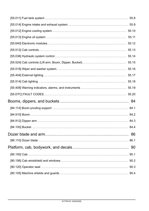
Booms, dippers, and buckets
– Boom pivoting support
— Boom pivoting support
— Boom pivoting support – Service limits – Cylinders pins and bushings
— Boom and swing support
— Boom and swing support – Remove
— Boom and swing support – Install
– Boom
— Boom
— Boom – Service limits – Cylinders pins and bushings
— Boom
— Boom – Prepare
— Boom – Remove
— Boom – Install
– Dipper arm
— Dipper arm
— Dipper arm – Service limits – Cylinders pins and bushings
— Dipper arm – Dimension – Dipper end, bucket and linkage dimensions
— Dipper
— Dipper – Prepare
— Dipper – Remove
— Dipper – Install
– Bucket
— Bucket
— Bucket – Service limits – Cylinders pins and bushings
— Link and rod
— Link and rod – Service limits – Cylinders pins and bushings
— Bucket
— Bucket – Prepare
— Bucket – Remove
— Bucket – Install
Dozer blade and arm
– Dozer blade
— Dozer blade
— Dozer blade – Service limits – Cylinders pins and bushings
— Dozer blade
— Dozer blade – Remove
— Dozer blade – Install
— Dozer blade – Remove (angle blade)
— Dozer blade – Install (angle blade)
Platform, cab, bodywork, and decals
– Cab
— Cab and platform
— Cab and platform – Remove
— Cab and platform – Install
– Cab windshield and windows
— Cab windshield glass
— Cab windshield glass – Adjust
— Side cab window glass
— Side cab window glass – Replace – Left-hand side
—- Cab window glass removal
—- Cab window glass installation
— Side cab window glass – Replace – Right-hand side
—- Cab window glass removal
—- Cab window glass installation
– Operator seat
— Operator seat
— Operator seat – Remove
— Operator seat – Install
– Machine shields and guards
— Engine hood
— Engine hood – Remove
— Engine hood – Install



Reviews
There are no reviews yet.