Technical Manual Hitachi ZW370 Wheel Loader TT97C5-E-02 (Preview)
Foreword
Safety Precautions
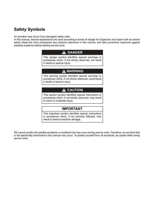
Safety Symbols
Symbols
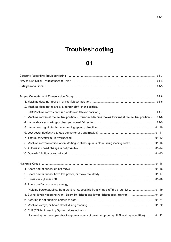
Troubleshooting
01
Error code (for chassis) 01-35
Error code (for engine) 01-38
Air conditioner 01-44
Cautions Regarding Troubleshooting
How to Use Quick Troubleshooting Table
Safety Precautions
Torque Converter and Transmission Group
1. Machine dose not move in any shift lever position.
2. Machine dose not move at a certain shift lever position. (OR:Machine moves only in a certain shift lever position.)
3. Machine moves at the neutral position. (Example: Machine moves forward at the neutral position.)
4. Large shock at starting or changing speed / direction
5. Large time lag at starting or changing speed / direction
6. Low power (Defective torque converter or transmission)
7. Torque converter oil is overheating.
8. Machine moves reverse when starting to climb up on a slope using inching brake.
9. Automatic speed change is not possible.
10. Downshift button does not work.
Hydraulic Group
1. Boom and/or bucket do not move.
2. Boom and/or bucket have low power, or move too slowly.
3. Excessive cylinder drift
4. Boom and/or bucket are spongy. (Holding bucket against the ground is not possible-front wheels off the ground.)
5. Bucket leveler does not work. Boom lift kickout and lower kickout does not work.
6. Steering is not possible or hard to steer.
7. Machine sways, or has a shock during steering
8. ELS (Efficient Loading System) does not work. (Excavating and scooping tractive power does not become up during ELS working condition)
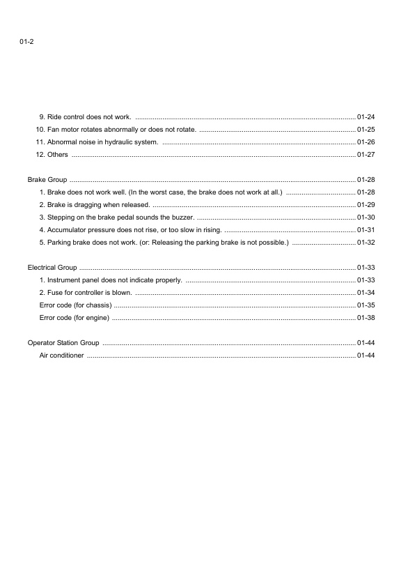
9. Ride control does not work.
10. Fan motor rotates abnormally or does not rotate.
11. Abnormal noise in hydraulic system.
12. Others
Brake Group
1. Brake does not work well. (In the worst case, the brake does not work at all.)
2. Brake is dragging when released.
3. Stepping on the brake pedal sounds the buzzer.
4. Accumulator pressure does not rise, or too slow in rising.
5. Parking brake does not work. (or: Releasing the parking brake is not possible.)
Electrical Group
1. Instrument panel does not indicate properly.
2. Fuse for controller is blown.
Error code (for chassis)
Error code (for engine)
Operator Station Group
Air conditioner
MEMO
Measurement for Performance Check
03
Cautions on Safety 03-2
Standard Measurement Values for Performance Check 03-3
Preparation for Performance Check 03-6
Engine 03-8
Measuring engine speed 03-8
Clutch Oil Pressure and Time Lag 03-12
Measuring clutch oil pressure 03-12
Hydraulic Cylinder 03-15
Cylinder natural drift 03-15
Boom Cycle Time 03-17
Full Steering Time 03-19
Loading/Steering Circuit Relief Valve 03-21
Loading circuit relief valve setting pressures 03-21
Steering circuit relief valve setting pressures 03-26
Stop Valve 03-32
Stop valve adjustment procedure 03-32
Fan Revolution 03-33
Service Brake 03-34
Service brake performance check 03-34
Parking Brake 03-35
Parking brake performance check 03-35
Brake Circuit Oil Pressure 03-36
Unloader valve setting pressure 03-36
Brake valve oil pressure 03-39
Accumulator Circuit Charging Time 03-41
Number of Brake Pedal Applications 03-43
Declutch Engagement 03-44
Cautions on Safety
Standard Measurement Values for Performance Check
Preparation for Performance Check
Engine
Measuring engine speed
Measurement instrument
Standard measurement value
Clutch Oil Pressure and Time Lag
Measuring clutch oil pressure
Measurement instrument
Gauge port
Standard measurement value
Clutch oil pressure measurement procedure
Time lag measurement procedure
Possible causes for low clutch pressure and clutch time lag
Hydraulic Cylinder
Cylinder natural drift
Measurement instrument
Standard measurement value (mm/min) (in/min)
Measurement procedure
Possible causes of excessive cylinder drift
Boom Cycle Time
Measurement instrument
Warm-up the engine before measuring boom rising time.
Standard measurement value (sec)
Measurement procedure
Full Steering Time
Measurement instrument
Warm-up the engine before measuring full steering time.
Standard measurement value (sec)
Measurement procedure
Loading/Steering Circuit Relief Valve
Loading circuit relief valve setting pressures
Measurement instruments
Gauge port
Standard measurement value MPa (kgf/cm2) (psi)
Measuring loading circuit main relief pressure
Measuring loading circuit overload relief pressure
Measuring pilot circuit relief pressure
Steering circuit relief valve setting pressures
Measurement instruments
Gauge port
Standard measurement value MPa (kgf/cm2) (psi)
Measuring steering circuit main relief pressure
Measuring steering circuit overload relief pressure
Measuring pilot circuit relief pressure (reducing pressure)
Stop Valve
Stop valve adjustment procedure
Fan Revolution
Measurement instrument
Measuring number of fan maximum revolutions
Service Brake
Service brake performance check
Condition
Standard measurement value
Parking Brake
Parking brake performance check
Condition
Standard measurement value
Brake Circuit Oil Pressure
Unloader valve setting pressure
Measurement instrument
Gauge port
Standard measurement value
Measurement procedure
Brake valve oil pressure
Brake valve performance
Accumulator Circuit Charging Time
Measurement instrument
Gauge installation position
Standard measurement valve (sec)
Measurement procedure
Number of Brake Pedal Applications
Standard measurement value
Measurement procedure
Possible causes of extremely low measurement value and solution
Declutch Engagement
Measurement instrument
Warm-up the engine before measuring declutch engagement
Standard measurement value
Cause of extremely high measurement value and solution
Measurement procedure
MEMO
Maintenance Log
Notes




Reviews
There are no reviews yet.