TTDB050-EN-00
– INTRODUCTION
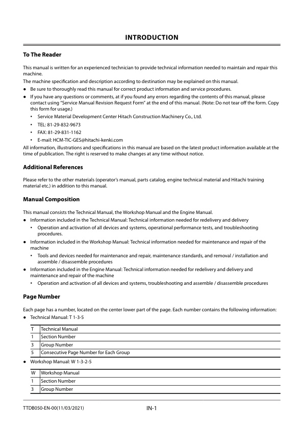
— To The Reader
— Additional References
— Manual Composition
— Page Number
— Trademark
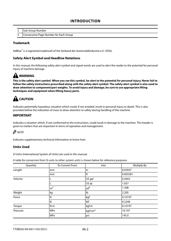
— Safety Alert Symbol and Headline Notations
— Units Used
– SYMBOL AND ABBREVIATION
— Symbol and Abbreviation
– CONTRASTING LIST OF PART NAME
— Contrasting List of Part Name between Technical Manual and Parts Catalog
– SAFETY
— Recognize Safety Information
— Understand Signal Words
— Follow Safety Instructions
— Prepare for Emergencies
— Wear Protective Clothing
— Protect Against Noise
— Inspect Machine
— General Precautions for the Cab
— Use Handrail and Steps
— Adjust the Operator’s Seat
— Ensure Safety Before Rising from or Leaving Operator’s Seat
— Fasten Your Seat Belt
— Move and Operate Machine Safely
— Start the Engine Only from Operator’s Seat
— Jump Starting
— Keep Riders off Machine
— Precautions for Operations
— Perform Job Site Risk Assessment Beforehand
— Install OPG Guard
— Restriction of Attachment Installation
— Provide Signals for Jobs Involving Multiple Machines
— Confirm Direction of Machine Travel
— Drive Machine Safely
— Avoid Injury from Rollaway Accidents
— Avoid Accidents from Reversing and Swing Operation
— Keep People Clear from Working Area
— Never Position the Bucket Over Anyone
— Avoid Undercutting
— Avoid Tipping
— Never Undercut a High Bank
— Dig with Caution
— Caution with an Overhead Obstacle
— Avoid Power Lines
— Precautions for Lightning
— Object Handling
— Protect Against Flying Debris and Falling Object
— Park Machine Safely
— Handle Fluids Safely−Avoid Fires
— Transport Safely
— Practice Maintenance Safely
— Warn Others of Service Work
— Support Machine Properly
— Stay Clear of Moving Parts
— Prevent Parts from Flying
— Avoid Injury from Attachment Falling Accident
— Prevent Burns
— Replace Rubber Hoses Periodically
— Avoid High-Pressure Fluids
— Prevent Fires
— Check for Oil Leaks:
— Check for Short circuits:
— Clean up Flammable Materials:
— Check Key Switch:
— Check Heat Shields:
— Evacuating in Case of Fire
— Beware of Exhaust Fumes
— Precautions for Welding and Grinding
— Avoid Heating Near Pressurized Fluid Lines
— Avoid Applying Heat to Lines Containing Flammable Fluids
— Precautions for Handling Accumulator and Gas Damper
— Remove Paint Before Welding or Heating
— Beware of Asbestos and Silica Dust and Other Contamination
— Prevent Battery Explosions
— Service Air Conditioning System Safely
— Handle Chemical Products Safely
— Dispose of Waste Properly
— Never Ride Attachment
— Notes on Aftertreatment Device
— Precautions for Communication Terminal
— Precautions for Communication Terminal Equipment
— Notes on Protection by Operator’s Station when the Machine Rolls Over
— Before Returning the Machine to the Customer
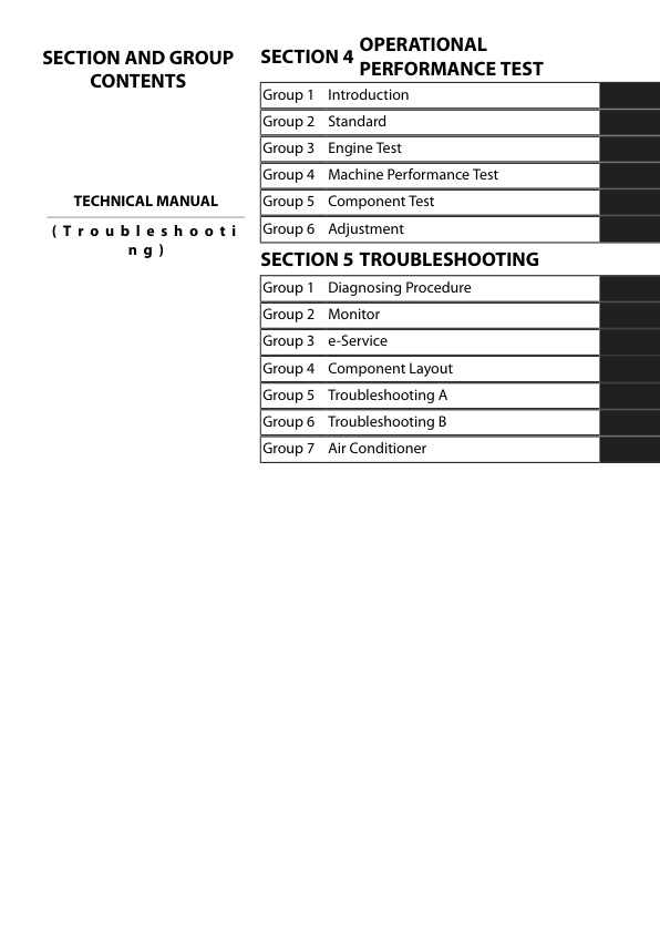
– SECTION AND GROUP CONTENTS
– CONTENTS
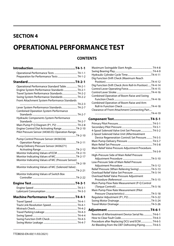
– OPERATIONAL PERFORMANCE TEST
— Introduction
— Operational Performance Tests
— Preparation for Performance Tests
— Standard
— Operational Performance Standard Table
— Engine System Performance Standards
— Travel System Performance Standards
— Swing System Performance Standards
— Front Attachment System Performance Standards
— Lever System Performance Standards
— Combined Operation System Performance Standards
— Hydraulic Components System Performance Standards
— Main Pump P-Q Diagram (P1, P2)
— Engine Control Dial Activating Range
— Pilot Pressure Sensor (4436535) Operation Range
— Pump Control Pressure Sensor (4436536) Operation Range
— Pump Delivery Pressure Sensor (4436271) Activating Range
— Monitor Indicating Values of ECM
— Monitor Indicating Values of MC
— Monitor Indicating Values of MC (Pressure Sensor)
— Monitor Indicating Values of MC (Solenoid Valve)
— Monitor Indicating Values of Switch Box Controller
— Engine Test
— Engine Speed
— Lubricant Consumption
— Machine Performance Test
— Travel Speed
— Track Link Revolution Speed
— Mistrack Check
— Travel Parking Leakage
— Swing Speed
— Swing Function Drift Check
— Swing Motor Leakage
— Maximum Swingable Slant Angle
— Swing Bearing Play
— Hydraulic Cylinder Cycle Time
— Dig Function Drift Check (Maximum Reach Position)
— Dig Function Drift Check (Arm Roll-In Position)
— Control Lever Operating Force
— Control Lever Stroke
— Combined Operation of Boom Raise and Swing Function Check
— Combined Operation of Boom Raise and Arm Roll-In Function Check
— Clearance of Front Attachment Connecting Part
— Component Test
— Primary Pilot Pressure
— Secondary Pilot Pressure
— 4-Spool Solenoid Valve Unit Set Pressure
— 2-Spool Solenoid Valve Unit (Aftertreatment Device Regeneration Control) Set Pressure
— Main Pump Delivery Pressure
— Main Relief Set Pressure
— Main Relief Valve Pressure Adjustment Procedure
— High-Pressure Side of Main Relief Pressure Adjustment Procedure
— Low-Pressure Side of Main Relief Pressure Adjustment Procedure
— Relief Pressure (When Relieving Swing)
— Overload Relief Valve Set Pressure
— Overload Relief Valve Pressure Adjustment Procedure (Reference)
— Main Pump Flow Rate Measurement (P-Q Control (Torque Control))
— Main Pump Flow Rate Measurement (Pilot Pressure Characteristics)
— Regulator Adjustment (P1, P2)
— Swing Motor Drainage
— Travel Motor Drainage
— Adjustment
— Rewrite of Aftertreatment Device Serial No.
— How to Clear Fault Code
— Procedure after Replacing DCU and ECM
— Air Bleeding from the DEF Defrosting Piping
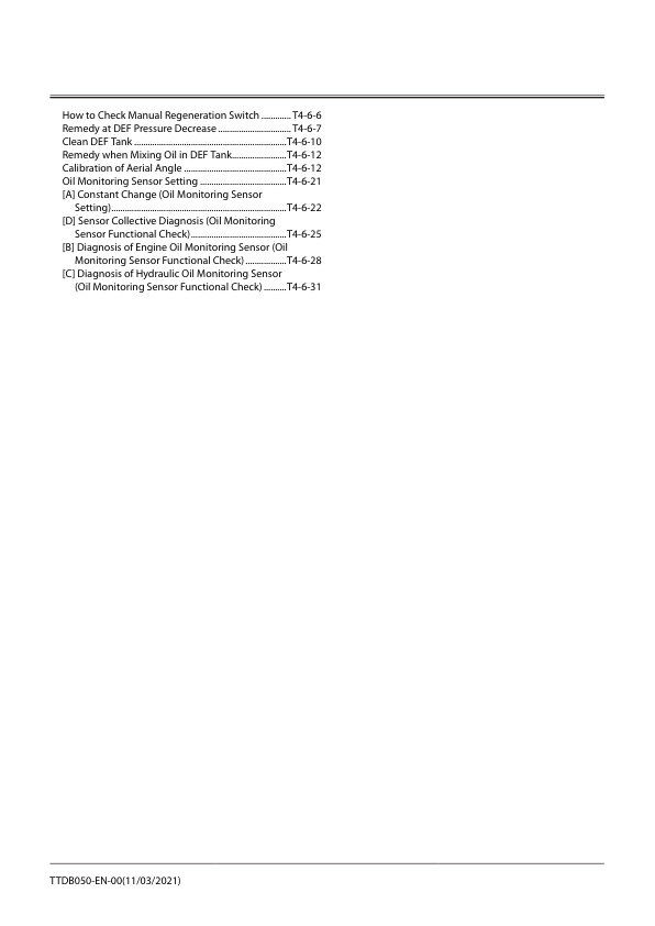
— How to Check Manual Regeneration Switch
— Remedy at DEF Pressure Decrease
— Clean DEF Tank
— Remedy when Mixing Oil in DEF Tank
— Calibration of Aerial Angle
— Oil Monitoring Sensor Setting
— [A] Constant Change (Oil Monitoring Sensor Setting)
— [D] Sensor Collective Diagnosis (Oil Monitoring Sensor Functional Check)
— [B] Diagnosis of Engine Oil Monitoring Sensor (Oil Monitoring Sensor Functional Check)
— [C] Diagnosis of Hydraulic Oil Monitoring Sensor (Oil Monitoring Sensor Functional Check)
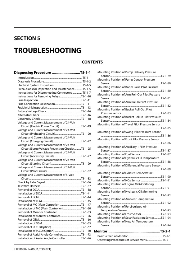
– TROUBLESHOOTING
— Diagnosing Procedure
— Introduction
— Diagnosis Procedure
— Electrical System Inspection
— Precautions for Inspection and Maintenance
— Instructions for Disconnecting Connectors
— Instructions for Removing Relays
— Fuse Inspection
— Fuse Connection Destination
— Fusible Link Inspection
— Battery Voltage Check
— Alternator Check
— Continuity Check
— Voltage and Current Measurement of 24-Volt Circuit (Electric Power Circuit)
— Voltage and Current Measurement of 24-Volt Circuit (Preheating Circuit)
— Voltage and Current Measurement of 24-Volt Circuit (Charging Circuit)
— Voltage and Current Measurement of 24-Volt Circuit (Surge Voltage Prevention Circuit)
— Voltage and Current Measurement of 24-Volt Circuit (Accessory Circuit)
— Voltage and Current Measurement of 24-Volt Circuit (Starting Circuit)
— Voltage and Current Measurement of 24-Volt Circuit (Pilot Circuit)
— Voltage and Current Measurement of 5-Volt Circuit
— Check by False Signal
— Test Wire Harness
— Removal of DCU
— Installation of DCU
— Removal of ECM
— Installation of ECM
— Removal of MC (Main Controller)
— Installation of MC (Main Controller)
— Removal of Monitor Controller
— Installation of Monitor Controller
— Removal of GSM
— Installation of GSM
— Removal of PLCU (Option)
— Installation of PLCU (Option)
— Removal of Aerial Angle Controller
— Installation of Aerial Angle Controller
— Mounting Position of Pump Delivery Pressure Sensor
— Mounting Position of Pump Control Pressure Sensor
— Mounting Position of Boom Raise Pilot Pressure Sensor
— Mounting Position of Arm Roll-Out Pilot Pressure Sensor
— Mounting Position of Arm Roll-In Pilot Pressure Sensor
— Mounting Position of Bucket Roll-Out Pilot Pressure Sensor
— Mounting Position of Bucket Roll-In Pilot Pressure Sensor
— Mounting Position of Travel Pilot Pressure Sensor
— Mounting Position of Swing Pilot Pressure Sensor
— Mounting Position of Front Pilot Pressure Sensor
— Mounting Position of Auxiliary 1 Pilot Pressure Sensor
— Mounting Position of Fuel Sensor
— Mounting Position of Hydraulic Oil Temperature Sensor
— Mounting Position of Differential Pressure Sensor
— Mounting Position of Exhaust Temperature Sensor
— Mounting Position of NOx Sensor
— Mounting Position of Engine Oil Monitoring Sensor
— Mounting Position of Hydraulic Oil Monitoring Sensor
— Mounting Position of Ambient Temperature Sensor
— Mounting Position of Re-circulated Air Temperature Sensor
— Mounting Position of Frost Sensor
— Mounting Position of Solar Radiation Sensor
— Mounting Position of New Air Temperature Sensor
— Monitor
— Basic Screen of Monitor
— Operating Procedures of Service Menu
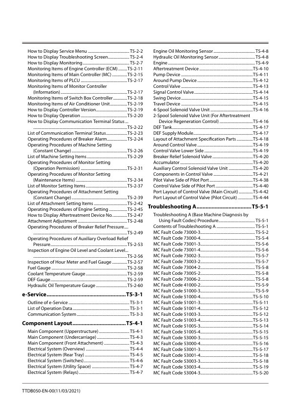
— How to Display Service Menu
— How to Display Troubleshooting Screen
— How to Display Monitoring
— Monitoring Items of Engine Controller (ECM)
— Monitoring Items of Main Controller (MC)
— Monitoring Items of PLCU
— Monitoring Items of Monitor Controller (Information)
— Monitoring Items of Switch Box Controller
— Monitoring Items of Air Conditioner Unit
— How to Display Controller Version
— How to Display Operation
— How to Display Communication Terminal Status
— List of Communication Terminal Status
— Operating Procedures of Breaker Alarm
— Operating Procedures of Machine Setting (Constant Change)
— List of Machine Setting Items
— Operating Procedures of Monitor Setting (Operation Permission)
— Operating Procedures of Monitor Setting (Maintenance Items)
— List of Monitor Setting Items
— Operating Procedures of Attachment Setting (Constant Change)
— List of Attachment Setting Items
— Operating Procedures of Engine Setting
— How to Display Aftertreatment Device No.
— Attachment Adjustment
— Operating Procedures of Breaker Relief Pressure
— Operating Procedures of Auxiliary Overload Relief Pressure
— Inspection of Engine Oil Level and Coolant Level
— Inspection of Hour Meter and Fuel Gauge
— Fuel Gauge
— Coolant Temperature Gauge
— DEF Gauge
— Hydraulic Oil Temperature Gauge
— e-Service
— Outline of e-Service
— List of Operation Data
— Communication System
— Component Layout
— Main Component (Upperstructure)
— Main Component (Undercarriage)
— Main Component (Front Attachment)
— Electrical System (Overview)
— Electrical System (Rear Tray)
— Electrical System (Switches)
— Electrical System (Utility Space)
— Electrical System (Relays)
— Engine Oil Monitoring Sensor
— Hydraulic Oil Monitoring Sensor
— Engine
— Aftertreatment Device
— Pump Device
— Around Pump Device
— Control Valve
— Signal Control Valve
— Swing Device
— Travel Device
— 4-Spool Solenoid Valve Unit
— 2-Spool Solenoid Valve Unit (For Aftertreatment Device Regeneration Control)
— DEF Tank
— DEF Supply Module
— Layout of Attachment Specification Parts
— Around Control Valve
— Control Valve Lower Side
— Breaker Relief Solenoid Valve
— Accumulator
— Auxiliary Control Solenoid Valve Unit
— Components in Control Valve
— Pilot Valve Side of Pilot Port
— Control Valve Side of Pilot Port
— Port Layout of Control Valve (Main Circuit)
— Port Layout of Control Valve (Pilot Circuit)
— Troubleshooting A
— Troubleshooting A (Base Machine Diagnosis by Using Fault Codes) Procedure
— Contents of Troubleshooting A
— MC Fault Code 73000-3
— MC Fault Code 73000-4
— MC Fault Code 73001-3
— MC Fault Code 73001-4
— MC Fault Code 73002-3
— MC Fault Code 73003-2
— MC Fault Code 73004-2
— MC Fault Code 73005-2
— MC Fault Code 73006-2
— MC Fault Code 41000-2
— MC Fault Code 51000-3
— MC Fault Code 51000-4
— MC Fault Code 51001-3
— MC Fault Code 51001-4
— MC Fault Code 51003-3
— MC Fault Code 51003-4
— MC Fault Code 51005-3
— MC Fault Code 51005-4
— MC Fault Code 53000-3
— MC Fault Code 53000-4
— MC Fault Code 53001-3
— MC Fault Code 53001-4
— MC Fault Code 53003-3
— MC Fault Code 53003-4
— MC Fault Code 53004-3
— MC Fault Code 53004-4
— MC Fault Code 53005-3
— MC Fault Code 53005-4
— MC Fault Code 53006-3
— MC Fault Code 53006-4
— MC Fault Code 53015-3
— MC Fault Code 53015-4
— MC Fault Code 53016-3
— MC Fault Code 53016-4
— MC Fault Code 51006-2
— MC Fault Code 51006-6
— MC Fault Code 51006-5
— MC Fault Code 51007-2
— MC Fault Code 51007-6
— MC Fault Code 51007-5
— MC Fault Code 51008-2
— MC Fault Code 51008-6
— MC Fault Code 51008-5
— MC Fault Code 51009-2
— MC Fault Code 51009-6
— MC Fault Code 51009-5
— MC Fault Code 51011-2
— MC Fault Code 51011-6
— MC Fault Code 51011-5
— MC Fault Code 51012-2
— MC Fault Code 51012-6
— MC Fault Code 51012-5
— MC Fault Code 51013-2
— MC Fault Code 51013-6
— MC Fault Code 51013-5
— MC Fault Code 51014-2
— MC Fault Code 51014-6
— MC Fault Code 51014-5
— MC Fault Code 51016-2
— MC Fault Code 51016-6
— MC Fault Code 51016-5
— MC Fault Code 51017-2
— MC Fault Code 51017-6
— MC Fault Code 51017-5
— MC Fault Code 51018-2
— MC Fault Code 51018-6
— MC Fault Code 51018-5
— MC Fault Code 51020-2
— MC Fault Code 51021-3
— MC Fault Code 51021-4
— MC Fault Code 51022-3
— MC Fault Code 51022-4
— MC Fault Code 51025-0
— MC Fault Code 51026-14
— MC Fault Code 63000-2
— MC Fault Code 73007-2
— MC Fault Code 73034-2
— MC Fault Code 73028-2
— MC Fault Code 41026-0
— MC Fault Code 41026-25
— MC Fault Code 41027-14
— MC Fault Code 41028-14
— MC Fault Code 41029-16
— MC Fault Code 41029-17
— MC Fault Code 41029-18
— MC Fault Code 50005-17
— Monitor Controller (Information) Fault Code 41001-2
— Monitor Controller (Information) Fault Code 41002-3
— Monitor Controller (Information) Fault Code 41003-3
— Monitor Controller (Information) Fault Code 41003-4
— Monitor Controller (Information) Fault Code 73033-2
— Monitor Controller (Information) Fault Code 41004-14
— Monitor Controller (Information) Fault Code 41005-14
— Monitor Controller (Information) Fault Code 41006-14
— Monitor Controller (Information) Fault Code 41007-14
— Monitor Controller (Information) Fault Code 41008-14
— Monitor Controller (Information) Fault Code 41004-20
— Monitor Controller (Information) Fault Code 73013-2
— Monitor Controller (Information) Fault Code 73014-2
— Monitor Controller (Information) Fault Code 73015-2
— Monitor Controller (Information) Fault Code 73016-2
— Monitor Controller (Information) Fault Code 73017-2
— Monitor Controller (Information) Fault Code 73018-2
— Monitor Controller (Information) Fault Code 73019-2
— Monitor Controller (Information) Fault Code 73020-2
— Monitor Controller (Information) Fault Code 73021-2
— Monitor Controller (Information) Fault Code 68004-12
— Monitor Controller (Information) Fault Code 68005-12
— Monitor Controller (Information) Fault Code 68006-12
— Monitor Controller (Information) Fault Code 68007-12
— Monitor Controller (Information) Fault Code 68008-12
— Monitor Controller (Information) Fault Code 68009-12
— Monitor Controller (Information) Fault Code 41002-4
— Monitor Controller (Information) Fault Code 73029-2
— Monitor Controller (Monitor) Fault Code 73010-2
— Monitor Controller (Monitor) Fault Code 73011-2
— Monitor Controller (Monitor) Fault Code 73012-2
— Monitor Controller (Monitor) Fault Code 73030-2
— Monitor Controller (Monitor) Fault Code 13911-3
— Monitor Controller (Monitor) Fault Code 13912-4
— Monitor Controller (Monitor) Fault Code 13913-3
— Monitor Controller (Monitor) Fault Code 13914-4
— Monitor Controller (Monitor) Fault Code 13917-3
— Monitor Controller (Monitor) Fault Code 13918-4
— Monitor Controller (Monitor) Fault Code 13921-3
— Monitor Controller (Monitor) Fault Code 13922-4
— Monitor Controller (Monitor) Fault Code 13943-2
— Monitor Controller (Monitor) Fault Code 13944-2
— Monitor Controller (Monitor) Fault Code 13951-2
— Monitor Controller (Monitor) Fault Code 13991-2
— Monitor Controller (Monitor) Fault Code 13992-2
— Switch Box Controller Fault Code 14504-3
— Switch Box Controller Fault Code 14504-4
— Aerial Angle Controller Fault Code 68000-2
— Aerial Angle Controller Fault Code 68001-2
— Aerial Angle Controller Fault Code 68002-2
— Aerial Angle Controller Fault Code 73022-2
— Aerial Angle Controller Fault Code 68003-2
— PLCU Fault Code 53007-3
— PLCU Fault Code 53007-4
— PLCU Fault Code 53008-3
— PLCU Fault Code 53008-4
— PLCU Fault Code 53009-12
— PLCU Fault Code 53009-7
— PLCU Fault Code 53010-12
— PLCU Fault Code 53010-7
— PLCU Fault Code 53011-2
— PLCU Fault Code 53011-6
— PLCU Fault Code 53011-5
— PLCU Fault Code 53012-2
— PLCU Fault Code 53012-6
— PLCU Fault Code 53012-5
— PLCU Fault Code 53013-2
— PLCU Fault Code 53013-6
— PLCU Fault Code 53013-5
— PLCU Fault Code 53014-2
— PLCU Fault Code 53014-6
— PLCU Fault Code 53014-5
— PLCU Fault Code 53017-2
— PLCU Fault Code 53018-2
— PLCU Fault Code 53019-2
— PLCU Fault Code 53020-2
— PLCU Fault Code 53021-2
— PLCU Fault Code 53009-8
— PLCU Fault Code 53010-8
— PLCU Fault Code 53017-8
— PLCU Fault Code 53020-8
— PLCU Fault Code 53018-8
— PLCU Fault Code 53021-8
— PLCU Fault Code 63001-3
— PLCU Fault Code 63001-4
— PLCU Fault Code 73023-2
— PLCU Fault Code 73035-7
— CAN0 Harness Check
— Body-CAN Harness Check
— CAN1 Harness Check
— IF-CAN Harness Check
— OPT-CAN Harness Check
— PL-CAN Harness Check
— ECM Fault Code List
— DCU Fault Code List
— Troubleshooting B
— Troubleshooting B (Machine Diagnosis by Using Trouble Symptom) Procedure
— Contents of Troubleshooting B
— Relationship between Machine Trouble Symptoms and Related Parts
— When a Fault Occurs in MC (Main Controller)
— When a Fault Occurs in Switch Box Controller
— When a Fault Occurs in Engine Control Dial
— When a Fault Occurs in Auto-Idle Switch
— When a Fault Occurs in Power Mode Switch
— When a Fault Occurs in Travel Mode Switch
— When a Fault Occurs in Power Digging Switch
— When a Fault Occurs in Pilot Shut-Off Switch (Pilot Shut-Off Lever)
— When a Fault Occurs in Manual Regeneration Switch
— When a Fault Occurs in Aerial Angle Switch
— When a Fault Occurs in Pilot Shut-Off Solenoid Valve
— When a Fault Occurs in Hydraulic Oil Temperature Sensor
— When a Fault Occurs in Differential Pressure Sensor
— When a Fault Occurs in DPF Inlet Temperature Sensor
— When a Fault Occurs in DPF Intermediate Temperature Sensor
— When a Fault Occurs in Pump 1 Delivery Pressure Sensor
— When a Fault Occurs in Pump 2 Delivery Pressure Sensor
— When a Fault Occurs in Pump 1 Control Pressure Sensor
— When a Fault Occurs in Pump 2 Control Pressure Sensor
— When a Fault Occurs Swing Pilot Pressure Sensor
— When a Fault Occurs in Boom Raise Pilot Pressure Sensor
— When a Fault Occurs in Arm 1 Roll-In Pilot Pressure Sensor
— When a Fault Occurs in Travel Pilot Pressure Sensor
— When a Fault Occurs in Front Pilot Pressure Sensor
— When a Fault Occurs in Bucket Roll-In Pilot Pressure Sensor
— When a Fault Occurs in Arm Roll-Out Pilot Pressure Sensor
— When a Fault Occurs in Bucket Roll-Out Pilot Pressure Sensor
— When a Fault Occurs in Auxiliary 1 Pilot Pressure Sensor (Option)
— When a Fault Occurs in Pump 1 and 2 Torque Control Solenoid Valve
— When a Fault Occurs in Maximum Pump 1 Flow Rate Limit Control Solenoid Valve
— When a Fault Occurs in Maximum Pump 2 Flow Rate Limit Control Solenoid Valve
— When a Fault Occurs in 4-Spool Solenoid Valve Unit (SG)
— When a Fault Occurs in 4-Spool Solenoid Valve Unit (SI)
— When a Fault Occurs in 4-Spool Solenoid Valve Unit (SF)
— When a Fault Occurs in 4-Spool Solenoid Valve Unit (SC)
— When a Fault Occurs in 2-Spool Solenoid Valve Unit (SZ)
— When a Fault Occurs in 2-Spool Solenoid Valve Unit (SJ)
— When a Fault Occurs in Main Relief Valve (For P1, P2)
— When a Fault Occurs in Overload Relief Valve
— When a Fault Occurs in Boom Anti-Drift Valve
— When a Fault Occurs in Arm Rod Anti-Drift Valve
— When a Fault Occurs in Arm Bottom Anti-Drift Valve
— When a Fault Occurs in Flow Combiner Valve
— When a Fault Occurs in Boom Regenerative Valve
— When a Fault Occurs in Arm Regenerative Valve
— When a Fault Occurs in Bucket Regenerative Valve
— When a Fault Occurs in Arm 1 Flow Rate Control Valve
— When a Fault Occurs in Auxiliary Flow Rate Control Valve
— When a Fault Occurs in Auxiliary Flow Combiner Valve
— When a Fault Occurs in Pump 1 Bypass Shut-Out Valve
— When a Fault Occurs in Digging Regenerative Valve
— When a Fault Occurs in Boom Lower Meter-In Cut Valve
— When a Fault Occurs in Travel Motor Displacement Angle Control Valve
— When a Fault Occurs in Pump 1 Flow Rate Control Valve
— When a Fault Occurs in Pump 2 Flow Rate Control Valve
— When a Fault Occurs in Swing Parking Brake Release Spool
— When a Fault Occurs in Flow Combiner Valve Control Spool
— When a Fault Occurs in Auxiliary Flow Combiner Control Solenoid Valve (Option)
— When a Fault Occurs in Auxiliary Flow Rate Control Solenoid Valve (Option)
— When a Fault Occurs in Selector Valve Control Solenoid Valve (Option)
— When a Fault Occurs in Selector Valve (Option)
— When a Fault Occurs in Breaker Relief Solenoid Valve (Option)
— When a Fault Occurs in Auxiliary Overload Relief Solenoid Valve (Option)
— Identification Symbol of Troubleshooting B
— Correlation between Trouble Symptoms and Part Failures
— Parts Related with “E-1 Starter does not rotate.”
— Parts Related with “E-2 Even if starter rotates, engine does not start.”
— Parts Related with “E-3 Even if power mode switch is operated, power mode is not shifted.”
— Parts Related with “E-4 ECO mode is faulty.”
— Parts Related with “E-5 Travel HP mode is faulty.”
— Parts Related with “E-6 Auto-idle system is faulty.”
— Parts Related with “E-8 Engine speed does not increase when coolant temperature is low.”
— Parts Related with “E-9 Auto shut-down is not activated.”
— Parts Related with “E-12 Engine speed does not decrease when audio mute/one-touch idle switch is pushed.”
— Parts Related with “A-1 All actuators do not work.”
— Parts Related with “A-2 All actuator speeds are slow.”
— Parts Related with “A-3 Actuator does not stop even if control lever is set to neutral.”
— Parts Related with “A-4 Manual regeneration of aftertreatment device cannot be performed.”
— Parts Related with “A-5 Travel (right) operation speed is slow when performing travel single operation. Bucket single operation speed is slow. (All problems occur at the same time.)”
— Parts Related with “A-6 Travel (left) operation speed is slow when performing travel single operation. Attachment single operation speed is slow. (All problems occur at the same time.)”
— Parts Related with “A-9 Swing single operation speed is slow. Boom speed is slightly slow when performing arm level crowding operation. (All problems occur at the same time.)”
— Parts Related with “F-1 All front attachment actuator powers are weak.”
— Parts Related with “F-2 Front attachment drifts remarkably.”
— Parts Related with “F-3 When boom raise or arm roll-out is operated, boom or arm starts to move after moving slightly down.”
— Parts Related with “F-4 Even if power digging switch is pushed, power does not increase. Boom raise power is weak when performing digging operation.”
— Parts Related with “F-5 Boom, arm, or bucket single operation is not operated. Boom, arm, or bucket single operation speed is slow.”
— Parts Related with “F-6 Bucket roll-in operating speed is slow or power is weak when performing digging operation.”
— Parts Related with “F-7 When performing combined operation, arm does not start to move smoothly. Arm starts to move slightly slow when performing arm single operation. These troubles often occur when temperature is low.”
— Parts Related with “F-8 When performing combined operation, boom does not start to move smoothly. Boom starts to move slightly slow when performing boom lower single operation.”
— Parts Related with “F-9 Boom lower speed above ground is faster than other actuators when performing combined operation. Machine cannot be raised off the ground.”
— Parts Related with “F-10 Arm roll-in speed is slow when performing digging operation.”
— Parts Related with “F-11 Arm speed is slow when performing combined operation. Boom raise speed is slow when performing combined operation of boom raise, and arm roll-in. Arm speed is slow when performing arm level crowding operation.
— Parts Related with “F-12 Arm roll-out speed is slow when performing combined operation of boom raise, arm roll-out, and attachment.”
— Parts Related with “F-14 Boom raise or attachment speed is slow when performing combined operation of boom raise and arm or attachment and arm.”
— Parts Related with “F-16 Boom raise speed is slow when performing combined operation of swing and boom raise.”
— Parts Related with “S-1 Swing speed is slow or is not operated.”
— Parts Related with “S-2 Swing speed is slow when performing combined operation of swing and arm roll-in.” Swing operation begins with difficulty. Swing power is weak.”
— Parts Related with “T-1 Both of right and left travels are not operated or travel speed is slow.”
— Parts Related with “T-2 One side travel is not operated or travel speed is slow. Machine mistracks.”
— Parts Related with “T-3 Machine mistracks when performing combined operation of travel and front attachment.”
— Parts Related with “T-4 Fast travel can not be selected. Travel mode does not change from slow speed mode to fast speed mode.”
— Parts Related with “T-5 Occasionally, machine may mistrack when traveling with engine running at slow speed.”
— Parts Related with “T-6 Attachment speed is slow when performing attachment single operation. Travel speed is slow when performing combined operation of attachment and travel.”
— Parts Related with “O-1 Work light does not light.”
— Parts Related with “O-2 Cab light does not light.”
— Parts Related with “O-3 Wiper is not operated.”
— Parts Related with “O-4 Washer is not operated.”
— Parts Related with “O-5 Boom light does not light.”
— Parts Related with “O-6 Camera image does not change when aerial angle switch is pressed.”
— E-1 Starter does not rotate.
— E-2 Even if starter rotates, engine does not start.
— E-3 Even if power mode switch is operated, power mode is not shifted.
— E-4 ECO mode is faulty.
— E-5 Travel HP mode is faulty.
— E-6 Auto-idle system is faulty.
— E-8 Engine speed does not increase when coolant temperature is low.
— E-9 Auto shut-down is not activated.
— E-12 Engine speed does not decrease when audio mute/one-touch idle switch is pushed.
— A-1 All actuators do not work.
— A-2 All actuator speeds are slow.
— A-3 Actuator does not stop even if control lever is set to neutral.
— A-4 Manual regeneration of aftertreatment device cannot be performed.
— A-5 Travel (right) operation speed is slow when performing travel single operation. Bucket single operation speed is slow. (All problems occur at the same time.)
— A-6 Travel (left) operation speed is slow when performing travel single operation. Attachment single operation speed is slow. (All problems occur at the same time.)
— A-9 Swing single operation speed is slow. Boom speed is slightly slow when performing arm level crowding operation. (All problems occur at the same time.)
— F-1 All front attachment actuator powers are weak.
— F-2 Front attachment drifts remarkably.
— F-3 When boom raise or arm roll-out is operated, boom or arm starts to move after moving slightly down.
— F-4 Even if power digging switch is pushed, power does not increase. Boom raise power is weak when performing digging operation.
— F-5 Boom, arm, or bucket single operation is not operated. Boom, arm, or bucket single operation speed is slow.
— F-6 Bucket roll-in operating speed is slow or power is weak when performing digging operation.
— F-7 When performing combined operation, arm does not start to move smoothly. Arm starts to move slightly slow when performing arm single operation. These troubles often occur when temperature is low.
— F-8 When performing combined operation, boom does not start to move smoothly. Boom starts to move slightly slow when performing boom lower single operation.
— F-9 Boom lower speed above ground is faster than other actuators when performing combined operation. Machine cannot be raised off the ground.
— F-10 Arm roll-in speed is slow when performing digging operation.
— F-11 Arm speed is slow when performing combined operation. Boom raise speed is slow when performing combined operation of boom raise, and arm roll-in. Arm speed is slow when performing arm level crowding operation.
— F-12 Arm roll-out speed is slow when performing combined operation of boom raise, arm roll-out, and attachment.
— F-14 Boom raise or attachment speed is slow when performing combined operation of boom raise and arm or attachment and arm.
— F-16 Boom raise speed is slow when performing combined operation of swing and boom raise.
— S-1 Swing speed is slow or is not operated.
— S-2 Swing speed is slow when performing combined operation of swing and arm roll-in. Swing operation begins with difficulty. Swing power is weak.
— T-1 Both of right and left travels are not operated or travel speed is slow.
— T-2 One side travel is not operated or travel speed is slow. Machine mistracks.
— T-3 Machine mistracks when performing combined operation of travel and front attachment.
— T-4 Fast travel can not be selected. Travel mode does not change from slow speed mode to fast speed mode.
— T-5 Occasionally, machine may mistrack when traveling with engine running at slow speed.
— T-6 Attachment speed is slow when performing attachment single operation. Travel speed is slow when performing combined operation of attachment and travel.
— O-1 Work light does not light.
— O-2 Cab light does not light.
— O-3 Wiper is not operated.
— O-4 Washer is not operated.
— O-5 Boom light does not light.
— O-6 Camera image does not change when aerial angle switch is pressed.
— Exchange Inspection
— How to Lower Boom in Case of Emergency and When Engine Stops without Hose Rupture Valve
— How to Lowering Boom When Emergency and When Engine Stops with Hose Rupture Valve
— Attachment Circuit Pressure Release Procedure
— Air Conditioner
— Outline of Air Conditioner
— Component Layout of Air Conditioner
— Functions of Main Electrical Parts
— Troubleshooting of Air Conditioner
— Monitor Controller (Monitor) Fault Code 13911-3
— Monitor Controller (Monitor) Fault Code 13912-4
— Monitor Controller (Monitor) Fault Code 13913-3
— Monitor Controller (Monitor) Fault Code 13914-4
— Monitor Controller (Monitor) Fault Code 13917-3
— Monitor Controller (Monitor) Fault Code 13918-4
— Monitor Controller (Monitor) Fault Code 13921-3
— Monitor Controller (Monitor) Fault Code 13922-4
— Monitor Controller (Monitor) Fault Code 13943-2
— Monitor Controller (Monitor) Fault Code 13944-2
— Monitor Controller (Monitor) Fault Code 13951-2
— Monitor Controller (Monitor) Fault Code 13991-2
— Monitor Controller (Monitor) Fault Code 13992-2
— Faulty Cooling (1)
— Faulty Cooling (2)
— Faulty Cooling (3)
— Faulty Cooling (4)
— Faulty Cooling (5)
— Faulty Heating (1)
— Faulty Heating (2)
— Others
— Blower motor does not operate.
— Compressor clutch does not operate.
— Cooling Circuit Check by Using Manifold Gauge
— Work after Replacing Components
— Refill compressor oil
— Necessity of Purging
— Procedures for Charging Air Conditioner with Refrigerant
— Warm-Up Operation
— Hose and Pipe Tightening Torque
— Cleaning Method of Evaporator
– SERVICE MANUAL REVISION REQUEST FORM
– The Attached Diagram List
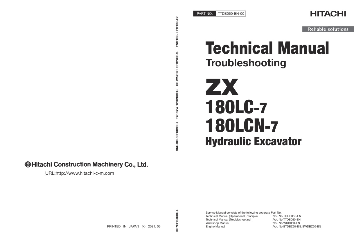
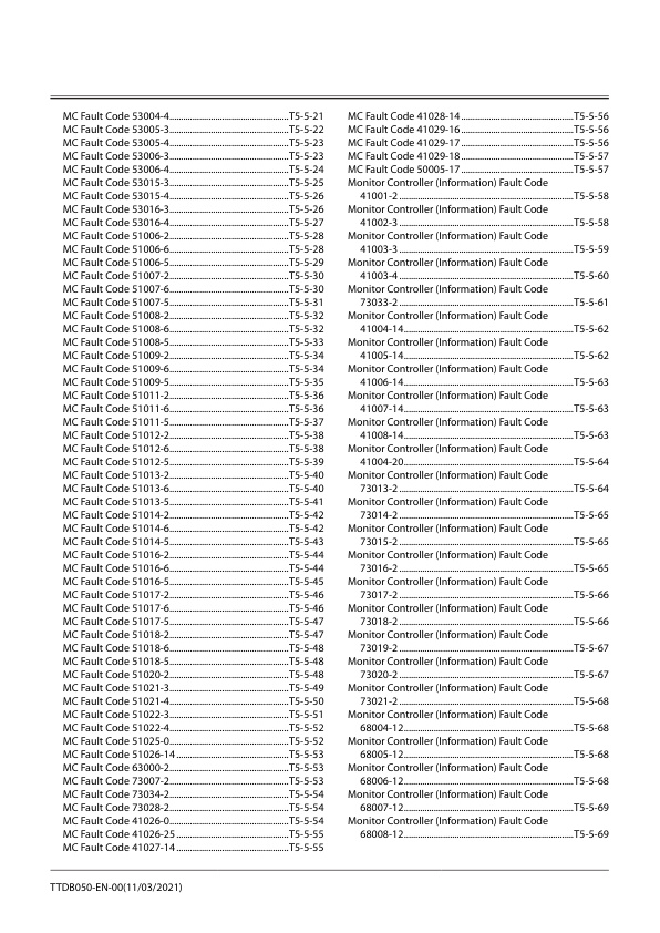
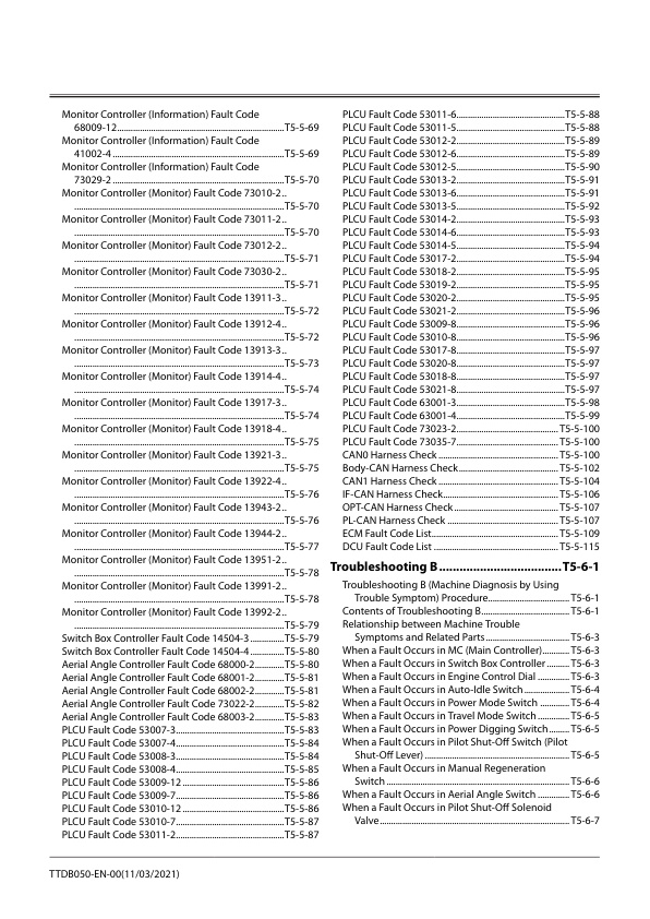
Technical Manual Hitachi ZX180LC-7, ZX180LCN-7 Hydraulic Excavator | TTDB050-EN-00 (2021.03.12)
9,99 $
Format: PDF
Type: Technical Manual
Pages: 632
Size: 49,9 Mb
No.: TTDB050-EN-00 (2021.03.12)
-
 Electrical & Hydraulic Circuit Diagram Hitachi ZX48U-6, ZX55U-6 | TAEP50-EN-01 (2023.12.07)
14,99 $
ADD TO CART
Electrical & Hydraulic Circuit Diagram Hitachi ZX48U-6, ZX55U-6 | TAEP50-EN-01 (2023.12.07)
14,99 $
ADD TO CART -
 Technical Manual Hitachi ZW30-5B Wheel Loader | TONBB-EN-00
9,99 $
ADD TO CART
Technical Manual Hitachi ZW30-5B Wheel Loader | TONBB-EN-00
9,99 $
ADD TO CART -
 Engine Parts Catalog Hitachi ZX30U-5N, ZX35U-5N Excavator | PADG-EG1-2
9,99 $
ADD TO CART
Engine Parts Catalog Hitachi ZX30U-5N, ZX35U-5N Excavator | PADG-EG1-2
9,99 $
ADD TO CART -
 Technical Manual Hitachi ZW120-6 Wheel Loader | TONSA60-EN-00
9,99 $
ADD TO CART
Technical Manual Hitachi ZW120-6 Wheel Loader | TONSA60-EN-00
9,99 $
ADD TO CART -
 Engine Parts Catalog Hitachi ZX300LC-7 Series Hydraulic Excavator | 6HK1-XBSA02-2
9,99 $
ADD TO CART
Engine Parts Catalog Hitachi ZX300LC-7 Series Hydraulic Excavator | 6HK1-XBSA02-2
9,99 $
ADD TO CART -
 Technical Manual Hitachi ZH200-5A, ZH200LC-5A Hybrid Excavator | TTDFM90-EN-00
9,99 $
ADD TO CART
Technical Manual Hitachi ZH200-5A, ZH200LC-5A Hybrid Excavator | TTDFM90-EN-00
9,99 $
ADD TO CART
Reviews
There are no reviews yet.