Technical Manual Hitachi ZX220W-7 Wheeled Excavator TTLCF50-EN-00 (2022.09.29) (Preview)
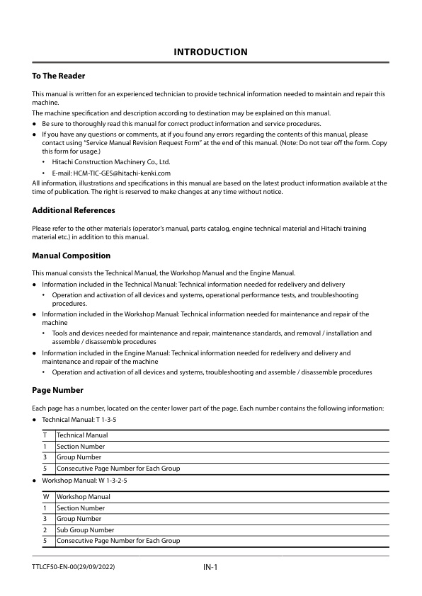
INTRODUCTION
– To The Reader
– Additional References
– Manual Composition
– Page Number
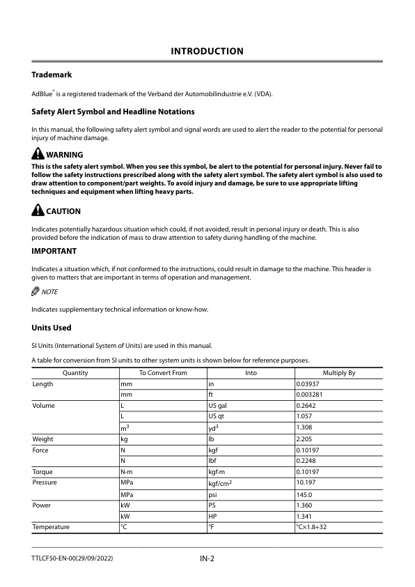
– Trademark
– Safety Alert Symbol and Headline Notations
– Units Used
SYMBOL AND ABBREVIATION
– Symbol and Abbreviation
CONTRASTING LIST OF PART NAME
– Contrasting List of Part Name between Technical Manual and Parts Catalog
SAFETY
– Recognize Safety Information
– Understand Signal Words
– Follow Safety Instructions
– Prepare for Emergencies
– Wear Protective Clothing
– Protect Against Noise
– Inspect Machine
– General Precautions for the Cab
– Use Handrail and Steps
– Adjust the Operator’s Seat
– Ensure Safety Before Rising from or Leaving Operator’s Seat
– Fasten Your Seat Belt
– Move and Operate Machine Safely
– Start the Engine Only from Operator’s Seat
– Jump Starting
– Keep Riders off Machine
– Precautions for Operations
– Perform Job Site Risk Assessment Beforehand
– Install OPG Guard
– Restriction of Attachment Installation
– Provide Signals for Jobs Involving Multiple Machines
– Confirm Direction of Machine to Be Driven
– Drive Machine Safely
–
– Avoid Injury from Rollaway Accidents
– Avoid Accidents from Reversing and Swing Operation
– Keep People Clear from Working Area
– Never Position the Bucket Over Anyone
– Avoid Undercutting
– Avoid Tipping
– Never Undercut a High Bank
– Dig with Caution
– Caution with an Overhead Obstacle
– Avoid Power Lines
– Precautions for Lightning
– Object Handling
– Protect Against Flying Debris and Falling Object
– Park Machine Safely
– Handle Fluids Safely−Avoid Fires
– Transport Safely
– Practice Maintenance Safely
– Warn Others of Service Work
– Support Machine Properly
– Stay Clear of Moving Parts
– Prevent Parts from Flying
– Avoid Injury from Attachment Falling Accident
– Support Maintenance Properly
– Prevent Burns
– Replace Rubber Hoses Periodically
– Avoid High-Pressure Fluids
– Prevent Fires
– Check for Oil Leaks:
– Check for Short circuits:
– Clean up Flammable Materials:
– Check Key Switch:
– Check Heat Shields:
– Evacuating in Case of Fire
– Beware of Exhaust Fumes
– Precautions for Welding and Grinding
– Avoid Heating Near Pressurized Fluid Lines
– Avoid Applying Heat to Lines Containing Flammable Fluids
– Precautions for Handling Accumulator and Gas Damper
– Remove Paint Before Welding or Heating
– Beware of Asbestos and Silica Dust and Other Contamination
– Prevent Battery Explosions
– Service Air Conditioning System Safely
– Handle Chemical Products Safely
– Dispose of Waste Properly
– Never Ride Attachment
– Notes on Aftertreatment Device
– Precautions for Communication Terminal
– Precautions for Communication Terminal Equipment
– Operation Stop Alarm (ZX135W-7/150W-7/155W-7/175W-7)
– Notes on Protection by Operator’s Station when the Machine Rolls Over
– Before Returning the Machine to the Customer
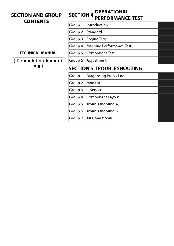
SECTION AND GROUP CONTENTS
CONTENTS
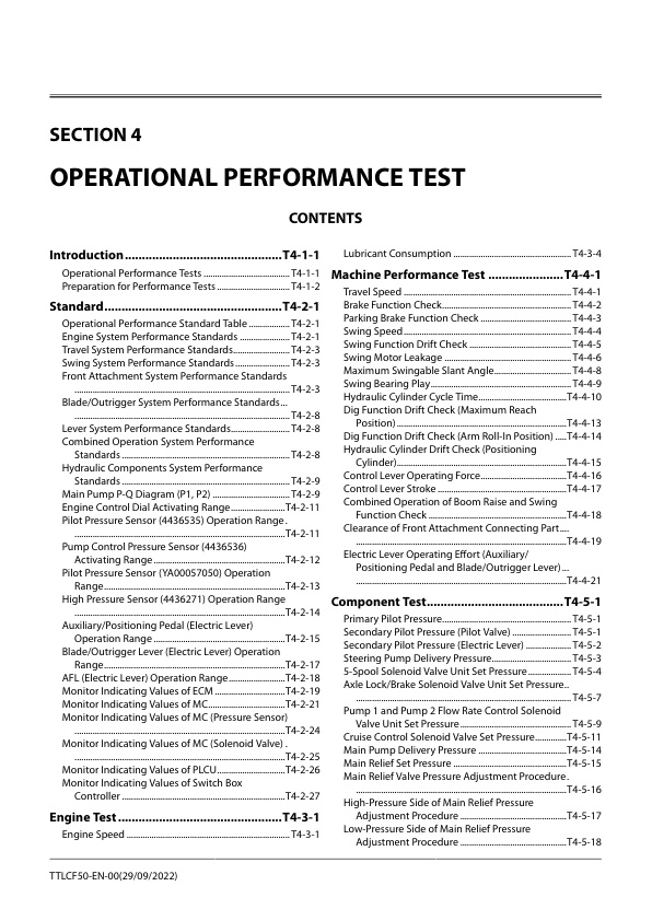
OPERATIONAL PERFORMANCE TEST
– Introduction
— Operational Performance Tests
— Preparation for Performance Tests
– Standard
— Operational Performance Standard Table
— Engine System Performance Standards
— Travel System Performance Standards
— Swing System Performance Standards
— Front Attachment System Performance Standards
— Blade/Outrigger System Performance Standards
— Lever System Performance Standards
— Combined Operation System Performance Standards
— Hydraulic Components System Performance Standards
— Main Pump P-Q Diagram (P1, P2)
— Engine Control Dial Activating Range
— Pilot Pressure Sensor (4436535) Operation Range
— Pump Control Pressure Sensor (4436536) Activating Range
— Pilot Pressure Sensor (YA00057050) Operation Range
— High Pressure Sensor (4436271) Operation Range
— Auxiliary/Positioning Pedal (Electric Lever) Operation Range
— Blade/Outrigger Lever (Electric Lever) Operation Range
— AFL (Electric Lever) Operation Range
— Monitor Indicating Values of ECM
— Monitor Indicating Values of MC
— Monitor Indicating Values of MC (Pressure Sensor)
— Monitor Indicating Values of MC (Solenoid Valve)
— Monitor Indicating Values of PLCU
— Monitor Indicating Values of Switch Box Controller
– Engine Test
— Engine Speed
— Lubricant Consumption
– Machine Performance Test
— Travel Speed
— Brake Function Check
— Parking Brake Function Check
— Swing Speed
— Swing Function Drift Check
— Swing Motor Leakage
— Maximum Swingable Slant Angle
— Swing Bearing Play
— Hydraulic Cylinder Cycle Time
— Dig Function Drift Check (Maximum Reach Position)
— Dig Function Drift Check (Arm Roll-In Position)
— Hydraulic Cylinder Drift Check (Positioning Cylinder)
— Control Lever Operating Force
— Control Lever Stroke
— Combined Operation of Boom Raise and Swing Function Check
— Clearance of Front Attachment Connecting Part
— Electric Lever Operating Effort (Auxiliary/Positioning Pedal and Blade/Outrigger Lever)
– Component Test
— Primary Pilot Pressure
— Secondary Pilot Pressure (Pilot Valve)
— Secondary Pilot Pressure (Electric Lever)
— Steering Pump Delivery Pressure
— 5-Spool Solenoid Valve Unit Set Pressure
— Axle Lock/Brake Solenoid Valve Unit Set Pressure
— Pump 1 and Pump 2 Flow Rate Control Solenoid Valve Unit Set Pressure
— Cruise Control Solenoid Valve Set Pressure
— Main Pump Delivery Pressure
— Main Relief Set Pressure
— Main Relief Valve Pressure Adjustment Procedure
— High-Pressure Side of Main Relief Pressure Adjustment Procedure
— Low-Pressure Side of Main Relief Pressure Adjustment Procedure
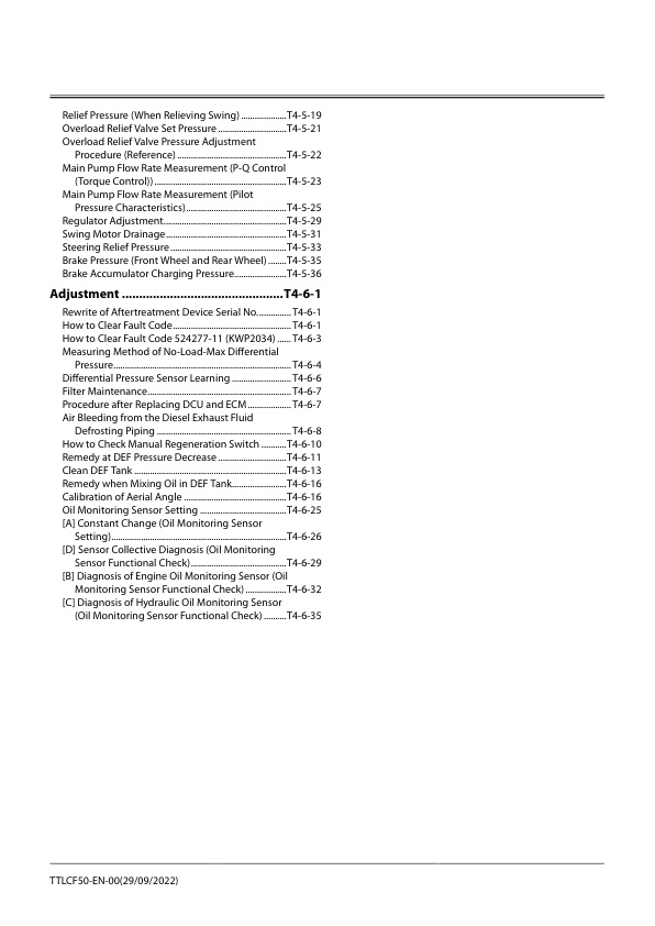
— Relief Pressure (When Relieving Swing)
— Overload Relief Valve Set Pressure
— Overload Relief Valve Pressure Adjustment Procedure (Reference)
— Main Pump Flow Rate Measurement (P-Q Control (Torque Control))
— Main Pump Flow Rate Measurement (Pilot Pressure Characteristics)
— Regulator Adjustment
— Swing Motor Drainage
— Steering Relief Pressure
— Brake Pressure (Front Wheel and Rear Wheel)
— Brake Accumulator Charging Pressure
– Adjustment
— Rewrite of Aftertreatment Device Serial No.
— How to Clear Fault Code
— How to Clear Fault Code 524277-11 (KWP2034)
— Measuring Method of No-Load-Max Differential Pressure
— Differential Pressure Sensor Learning
— Filter Maintenance
— Procedure after Replacing DCU and ECM
— Air Bleeding from the Diesel Exhaust Fluid Defrosting Piping
— How to Check Manual Regeneration Switch
— Remedy at DEF Pressure Decrease
— Clean DEF Tank
— Remedy when Mixing Oil in DEF Tank
— Calibration of Aerial Angle
— Oil Monitoring Sensor Setting
— [A] Constant Change (Oil Monitoring Sensor Setting)
— [D] Sensor Collective Diagnosis (Oil Monitoring Sensor Functional Check)
— [B] Diagnosis of Engine Oil Monitoring Sensor (Oil Monitoring Sensor Functional Check)
— [C] Diagnosis of Hydraulic Oil Monitoring Sensor (Oil Monitoring Sensor Functional Check)
TROUBLESHOOTING
– Diagnosing Procedure
— Introduction
— Diagnosis Procedure
— Electrical System Inspection
— Precautions for Inspection and Maintenance
— Instructions for Disconnecting Connectors
— Instructions for Removing Relays
— Fuse Inspection
— Fuse Connection Destination
— Fusible Link Inspection
— Battery Voltage Check
— Alternator Check
— Continuity Check
— Voltage and Current Measurement of 24-Volt Circuit
— Voltage and Current Measurement of 5-Volt Circuit
— Check by False Signal
— Test Wire Harness
— Electric Lever (Auxiliary, Positioning) Check
— Electric Lever (Blade/Outrigger) Check
— AFL Check
— Removal of ECM
— Installation of ECM
— Removal of DCU
— Installation of DCU
— Removal of VGS Controller
— Installation of VGS Controller
— Removal of MC (Main Controller)
— Installation of MC (Main Controller)
— Removal of Monitor Controller
— Installation of Monitor Controller
— Removal of GSM
— Installation of GSM
— Removal of PLCU
— Installation of PLCU
— Removal of Aerial Angle Controller
— Installation of Aerial Angle Controller
— Mounting Position of Pump Delivery Pressure Sensor
— Mounting Position of Pump Control Pressure Sensor
— Mounting Position of Boom Raise Pilot Pressure Sensor
— Mounting Position of Arm Roll-Out Pilot Pressure Sensor
— Mounting Position of Travel Forward Pilot Pressure Sensor and Travel Reverse Pilot Pressure Sensor
— Mounting Position of Arm 1 Roll-In Pilot Pressure Sensor
— Mounting Position of Swing Pilot Pressure Sensor
— Mounting Position of Front Pilot Pressure Sensor
— Mounting Position of Auxiliary 1 Pilot Pressure Sensor
— Mounting Position of Blade/Outrigger Pilot Pressure Sensor
— Mounting Position of Positioning Pilot Pressure Sensor
— Mounting Position of Steering Pump Delivery Pressure Sensor
— Mounting Position of Brake Residual Pressure Sensor
— Mounting Position of Travel N Sensor
— Mounting Position of Brake Pressure Sensor
— Mounting Position of AFL Pilot Hydraulic Oil Temperature Sensor
— Mounting Position of Assist Pilot Pressure Sensor
— Mounting Position of Fuel Sensor
— Mounting Position of Hydraulic Oil Temperature Sensor
— Mounting Position of Differential Pressure Sensor
— Mounting Position of Exhaust Temperature Sensor
— Mounting Position of NOx Sensor
— Mounting Position of Engine Oil Monitoring Sensor
— Mounting Position of Hydraulic Oil Monitoring Sensor
— Mounting Position of Ambient Temperature Sensor
— Mounting Position of Re-Circulated Air Temperature Sensor
— Mounting Position of Frost Sensor
— Mounting Position of Solar Radiation Sensor
– Monitor
— Basic Screen of Monitor
— Operating Procedures of Service Menu
— How to Display Service Menu
— How to Display Troubleshooting Screen
— How to Display Monitoring
— Monitoring Items of Engine Controller (ECM)
— Monitoring Items of Main Controller (MC)
— Monitoring Items of PLCU
— Monitoring Items of Monitor Controller (Information)
— Monitoring Items of Switch Box Controller
— Monitoring Items of Air Conditioner Unit
— How to Display Controller Version
— How to Display Operation
— How to Display Communication Terminal Status
— List of Communication Terminal Status
— Operating Procedures of Breaker Alarm
— Operating Procedures of Machine Setting (Constant Change)
— List of Machine Setting Items
— Operating Procedures of Monitor Setting (Operation Permission)
— Operating Procedures of Monitor Setting (Maintenance Items)
— List of Monitor Setting Items
— Operating Procedures of Attachment Setting (Constant Change)
— List of Attachment Setting Items
— Operating Procedures of Engine Setting
— How to Display Aftertreatment Device No.
— Attachment Adjustment
— Adjustment Procedures of Breaker Relief Solenoid Valve Set-Pressure
— Adjustment Procedures of Auxiliary Overload Relief Valve Set-Pressure
— Inspection of Engine Oil Level and Coolant Level
— Inspection of Hour Meter and Fuel Gauge
— Fuel Gauge
— Coolant Temperature Gauge
— DEF Gauge
— Hydraulic Oil Temperature Gauge
– e-Service
— Outline of e-Service
— List of Operation Data
— Communication System
– Component Layout
— Main Component (Upperstructure)
— Main Component (Undercarriage)
— Main Component (Front Attachment)
— Electrical System (Overview)
— Electrical System (Cab)
— Electrical System (Switches)
— Electrical System (Rear Tray)
— Relay Layout
— Electrical System (Utility Space)
— Electrical System (Relays)
— Electrical System (Lights)
— Engine Oil Monitoring Sensor
— Hydraulic Oil Monitoring Sensor
— Engine
— Aftertreatment Device
— Pump Device
— Around Pump Device
— Control Valve
— Signal Control Valve
— Swing Shockless Valve
— Swing Device
— Accumulator Charging Valve
— Travel Shockless Valve
— Travel Device
— Brake Valve
— 8-Spool Solenoid Valve Unit
— 5-Spool Solenoid Valve Unit
— 2-Spool Solenoid Valve Unit (For Assist) (Option)
— 2-Spool Solenoid Valve Unit (For Blade/Outrigger Cylinder) (Front) (Option)
— 2-Spool Solenoid Valve Unit (For Blade/Outrigger Cylinder) (Rear) (Option)
— Pump 1 and Pump 2 Flow Rate Control Solenoid Valve Unit
— Axle Lock/Brake Solenoid Valve Unit
— Transmission Control Solenoid Valve
— Cruise Stop Solenoid Valve
— Cruise Control Solenoid Valve
— DEF Tank
— DEF Supply Module
— Layout of Attachment Spec. Parts
— Auxiliary Control Solenoid Valve Unit
— Breaker Relief Solenoid Valve
— Selector Valve Control Valve
— Components in Control Valve
— Pilot Valve Side of Pilot Port
— Control Valve Side of Pilot Port
— Port Layout of Control Valve (Main Circuit)
— Port Layout of Control Valve (Pilot Circuit)
— Components in Positioning Control Valve
– Troubleshooting A
— Troubleshooting A (Base Machine Diagnosis by Using Fault Codes) Procedure
— Contents of Troubleshooting A
— MC Fault Code 73000-3
— MC Fault Code 73000-4
— MC Fault Code 73001-3
— MC Fault Code 73001-4
— MC Fault Code 73002-3
— MC Fault Code 73003-2
— MC Fault Code 73005-2
— MC Fault Code 73006-2
— MC Fault Code 41000-2
— MC Fault Code 51000-3
— MC Fault Code 51000-4
— MC Fault Code 51001-3
— MC Fault Code 51001-4
— MC Fault Code 51003-3
— MC Fault Code 51003-4
— MC Fault Code 51005-3
— MC Fault Code 51005-4
— MC Fault Code 53000-3
— MC Fault Code 53000-4
— MC Fault Code 53001-3
— MC Fault Code 53001-4
— MC Fault Code 53003-3
— MC Fault Code 53003-4
— MC Fault Code 53005-3
— MC Fault Code 53005-4
— MC Fault Code 53015-3
— MC Fault Code 53015-4
— MC Fault Code 51006-2
— MC Fault Code 51006-6
— MC Fault Code 51006-5
— MC Fault Code 51007-2
— MC Fault Code 51007-6
— MC Fault Code 51007-5
— MC Fault Code 51009-2
— MC Fault Code 51009-6
— MC Fault Code 51009-5
— MC Fault Code 51065-2
— MC Fault Code 51065-6
— MC Fault Code 51065-5
— MC Fault Code 51012-2
— MC Fault Code 51012-6
— MC Fault Code 51012-5
— MC Fault Code 51013-2
— MC Fault Code 51013-6
— MC Fault Code 51013-5
— MC Fault Code 51014-2
— MC Fault Code 51014-6
— MC Fault Code 51014-5
— MC Fault Code 51016-2
— MC Fault Code 51016-6
— MC Fault Code 51016-5
— MC Fault Code 51037-2
— MC Fault Code 51037-6
— MC Fault Code 51037-5
— MC Fault Code 51017-2
— MC Fault Code 51017-6
— MC Fault Code 51017-5
— MC Fault Code 51018-2
— MC Fault Code 51018-6
— MC Fault Code 51018-5
— MC Fault Code 51020-2
— MC Fault Code 55015-2
— MC Fault Code 55016-2
— MC Fault Code 55017-2
— MC Fault Code 51021-3
— MC Fault Code 51021-4
— MC Fault Code 51022-3
— MC Fault Code 51022-4
— MC Fault Code 51025-0
— MC Fault Code 51026-14
— MC Fault Code 63000-2
— MC Fault Code 73007-2
— MC Fault Code 73008-2
— MC Fault Code 73034-2
— MC Fault Code 73028-2
— MC Fault Code 41026-0
— MC Fault Code 41026-25
— MC Fault Code 41027-14
— MC Fault Code 41028-14
— MC Fault Code 41029-16
— MC Fault Code 41029-17
— MC Fault Code 41029-18
— MC Fault Code 51059-3
— MC Fault Code 51059-4
— MC Fault Code 51060-2
— MC Fault Code 51060-6
— MC Fault Code 51060-5
— MC Fault Code 51061-3
— MC Fault Code 51061-4
— MC Fault Code 51062-2
— MC Fault Code 51062-6
— MC Fault Code 51062-5
— MC Fault Code 50005-17
— Monitor Controller (Information) Fault Code 41001-2
— Monitor Controller (Information) Fault Code 41002-3
— Monitor Controller (Information) Fault Code 41003-3
— Monitor Controller (Information) Fault Code 41003-4
— Monitor Controller (Information) Fault Code 73033-2
— Monitor Controller (Information) Fault Code 41004-14
— Monitor Controller (Information) Fault Code 41005-14
— Monitor Controller (Information) Fault Code 41006-14
— Monitor Controller (Information) Fault Code 41007-14
— Monitor Controller (Information) Fault Code 41008-14
— Monitor Controller (Information) Fault Code 41004-20
— Monitor Controller (Information) Fault Code 73013-2
— Monitor Controller (Information) Fault Code 73014-2
— Monitor Controller (Information) Fault Code 73015-2
— Monitor Controller (Information) Fault Code 73016-2
— Monitor Controller (Information) Fault Code 73017-2
— Monitor Controller (Information) Fault Code 73018-2
— Monitor Controller (Information) Fault Code 73019-2
— Monitor Controller (Information) Fault Code 73020-2
— Monitor Controller (Information) Fault Code 73021-2
— Monitor Controller (Information) Fault Code 68004-12
— Monitor Controller (Information) Fault Code 68005-12
— Monitor Controller (Information) Fault Code 68006-12
— Monitor Controller (Information) Fault Code 68007-12
— Monitor Controller (Information) Fault Code 68008-12
— Monitor Controller (Information) Fault Code 68009-12
— Monitor Controller (Information) Fault Code 41002-4
— Monitor Controller (Information) Fault Code 73029-2
— Monitor Controller (Information) Fault Code 73069-2
— Monitor Controller (Monitor) Fault Code 73010-2
— Monitor Controller (Monitor) Fault Code 73011-2
— Monitor Controller (Monitor) Fault Code 73012-2
— Monitor Controller (Monitor) Fault Code 73030-2
— Monitor Controller (Monitor) Fault Code 13911-3
— Monitor Controller (Monitor) Fault Code 13912-4
— Monitor Controller (Monitor) Fault Code 13913-3
— Monitor Controller (Monitor) Fault Code 13914-4
— Monitor Controller (Monitor) Fault Code 13917-3
— Monitor Controller (Monitor) Fault Code 13918-4
— Monitor Controller (Monitor) Fault Code 13921-3
— Monitor Controller (Monitor) Fault Code 13922-4
— Monitor Controller (Monitor) Fault Code 13943-2
— Monitor Controller (Monitor) Fault Code 13944-2
— Monitor Controller (Monitor) Fault Code 13951-2
— Monitor Controller (Monitor) Fault Code 13991-2
— Monitor Controller (Monitor) Fault Code 13992-2
— Switch Box Controller Fault Code 14504-3
— Switch Box Controller Fault Code 14504-4
— Aerial Angle Controller Fault Code 68000-2
— Aerial Angle Controller Fault Code 68001-2
— Aerial Angle Controller Fault Code 68002-2
— Aerial Angle Controller Fault Code 73022-2
— Aerial Angle Controller Fault Code 68003-2
— PLCU Fault Code 53017-2
— PLCU Fault Code 53018-2
— PLCU Fault Code 53019-2
— PLCU Fault Code 53020-2
— PLCU Fault Code 53021-2
— PLCU Fault Code 53009-8
— PLCU Fault Code 53010-8
— PLCU Fault Code 53017-8
— PLCU Fault Code 53020-8
— PLCU Fault Code 53018-8
— PLCU Fault Code 53021-8
— PLCU Fault Code 63001-3
— PLCU Fault Code 63001-4
— PLCU Fault Code 73023-2
— PLCU Fault Code 73035-7
— PLCU Fault Code 55001-2
— PLCU Fault Code 53061-8
— PLCU Fault Code 53061-2
— PLCU Fault Code 53062-8
— PLCU Fault Code 53062-2
— PLCU Fault Code 53063-2
— PLCU Fault Code 53064-2
— PLCU Fault Code 53065-0
— PLCU Fault Code 53065-8
— PLCU Fault Code 53066-0
— PLCU Fault Code 53066-8
— PLCU Fault Code 53067-3
— PLCU Fault Code 53067-4
— PLCU Fault Code 53068-3
— PLCU Fault Code 53068-4
— PLCU Fault Code 53067-12
— PLCU Fault Code 53067-7
— PLCU Fault Code 53068-12
— PLCU Fault Code 53068-7
— PLCU Fault Code 53069-2
— PLCU Fault Code 53069-6
— PLCU Fault Code 53069-5
— PLCU Fault Code 53070-2
— PLCU Fault Code 53070-6
— PLCU Fault Code 53070-5
— PLCU Fault Code 53071-2
— PLCU Fault Code 53071-6
— PLCU Fault Code 53071-5
— PLCU Fault Code 53072-2
— PLCU Fault Code 53072-6
— PLCU Fault Code 53072-5
— PLCU Fault Code 53073-2
— PLCU Fault Code 53074-2
— PLCU Fault Code 53075-2
— PLCU Fault Code 53076-3
— PLCU Fault Code 53076-4
— PLCU Fault Code 53077-3
— PLCU Fault Code 53077-4
— PLCU Fault Code 53076-12
— PLCU Fault Code 53076-7
— PLCU Fault Code 53077-12
— PLCU Fault Code 53077-7
— PLCU Fault Code 53078-2
— PLCU Fault Code 53078-6
— PLCU Fault Code 53078-5
— PLCU Fault Code 53079-2
— PLCU Fault Code 53079-6
— PLCU Fault Code 53079-5
— PLCU Fault Code 53080-2
— PLCU Fault Code 53080-6
— PLCU Fault Code 53080-5
— PLCU Fault Code 53081-2
— PLCU Fault Code 53081-6
— PLCU Fault Code 53081-5
— PLCU Fault Code 55002-3
— PLCU Fault Code 55002-4
— PLCU Fault Code 55003-3
— PLCU Fault Code 55003-4
— PLCU Fault Code 55004-3
— PLCU Fault Code 55004-4
— PLCU Fault Code 55005-3
— PLCU Fault Code 55005-4
— PLCU Fault Code 55006-3
— PLCU Fault Code 55006-4
— PLCU Fault Code 55007-2
— PLCU Fault Code 55014-2
— PLCU Fault Code 55008-2
— PLCU Fault Code 55009-2
— PLCU Fault Code 51055-2
— PLCU Fault Code 51055-6
— PLCU Fault Code 51055-5
— PLCU Fault Code 55010-2
— PLCU Fault Code 55010-6
— PLCU Fault Code 55010-5
— PLCU Fault Code 55011-2
— PLCU Fault Code 55011-6
— PLCU Fault Code 55011-5
— PLCU Fault Code 55012-2
— PLCU Fault Code 55012-6
— PLCU Fault Code 55012-5
— PLCU Fault Code 55013-2
— PLCU Fault Code 55013-6
— PLCU Fault Code 55013-5
— PLCU Fault Code 53109-2
— PLCU Fault Code 55018-2
— PLCU Fault Code 55019-2
— PLCU Fault Code 55020-2
— PLCU Fault Code 55021-2
— PLCU Fault Code 53105-2
— PLCU Fault Code 53106-2
— PLCU Fault Code 53107-2
— PLCU Fault Code 53108-2
— PLCU Fault Code 55022-2
— Power-CAN harness Check
— Body-CAN Harness Check
— ISO-CAN (Engine) Harness Check
— IF-CAN Harness Check
— OPT-CAN Harness Check
— PL-CAN Harness Check
— ECM Fault Code List
— DCU Fault Code List
– Troubleshooting B
— Troubleshooting B (Machine Diagnosis by Using Trouble Symptom) Procedure
— Contents of Troubleshooting B
— Relationship between Machine Trouble Symptoms and Related Parts
— When a Fault Occurs in MC (Main Controller)
— When a Fault Occurs in PLCU
— When a Fault Occurs in Switch Box Controller
— When a Fault Occurs in Engine Control Dial
— When a Fault Occurs in Auto-Idle Switch
— When a Fault Occurs in Power Mode Switch
— When a Fault Occurs in Travel Mode Switch
— When a Fault Occurs in Power Digging Switch
— When a Fault Occurs in Pilot Shut-Off Switch (Pilot Shut-Off Lever)
— When a Fault Occurs in Manual Regeneration Switch
— When a Fault Occurs in Aerial Angle Switch
— When a Fault Occurs in FNR Switch
— When a Fault Occurs in Engine Speed Control Mode Selection Switch
— When a Fault Occurs in Brake Switch
— When a Fault Occurs in Working Brake Release Switch
— When a Fault Occurs in Blade/Outrigger Main Switch
— When a Fault Occurs in Blade/Outrigger Front-Rear Selection Switch
— When a Fault Occurs in Blade/Outrigger Left-Right Selection Switch
— When a Fault Occurs in Public Road Drive Switch
— When a Fault Occurs in Parking Switch
— When a Fault Occurs in Automatic Working Brake Switch
— When a Fault Occurs in Auto-Lubrication Reset Switch
— When a Fault Occurs in Cruise Main Switch
— When a Fault Occurs in Cruise Speed Set Switch
— When a Fault Occurs in Seat Heater Switch
— When a Fault Occurs in Pilot Shut-Off Solenoid Valve
— When a Fault Occurs in Hydraulic Oil Temperature Sensor
— When a Fault Occurs in Differential Pressure Sensor
— When a Fault Occurs in DOC Inlet Exhaust Temperature Sensor
— When a Fault Occurs in DOC Outlet Exhaust Temperature Sensor
— When a Fault Occurs in SCR Exhaust Temperature Sensor
— When a Fault Occurs in Pump 1 Delivery Pressure Sensor
— When a Fault Occurs in Pump 2 Delivery Pressure Sensor
— When a Fault Occurs in Steering Pump Delivery Pressure Sensor
— When a Fault Occurs in Brake Pressure Sensor
— When a Fault Occurs in Brake Residual Pressure Sensor
— When a Fault Occurs in Pump 1 Control Pressure Sensor
— When a Fault Occurs in Pump 2 Control Pressure Sensor
— When a Fault Occurs Swing Pilot Pressure Sensor
— When a Fault Occurs in Boom Raise Pilot Pressure Sensor
— When a Fault Occurs in Arm 1 Roll-In Pilot Pressure Sensor
— When a Fault Occurs in Travel Forward Pilot Pressure Sensor
— When a Fault Occurs in Travel Reverse Pilot Pressure Sensor
— When a Fault Occurs in Front Pilot Pressure Sensor
— When a Fault Occurs in Arm Roll-Out Pilot Pressure Sensor
— When a Fault Occurs in Auxiliary 1 Pilot Pressure Sensor (Option)
— When a Fault Occurs in Positioning Pilot Pressure Sensor
— When a Fault Occurs in Blade/Outrigger Pilot Pressure Sensor
— When a Fault Occurs in Assist Pilot Pressure Sensor (Option)
— When a Fault Occurs in Travel N Sensor
— When a Fault Occurs in Cruise Control Pressure Monitoring Sensor
— When a Fault Occurs in AFL Pilot Hydraulic Oil Temperature sensor
— When a Fault Occurs in Auto-Lubrication Grease Level Sensor
— When a Fault Occurs in Auto-Lubrication Stroke Sensor
— When a Fault Occurs in Pump 1 and 2 Torque Control Solenoid Valve
— When a Fault Occurs in Maximum Pump 1 Flow Rate Limit Control Solenoid Valve
— When a Fault Occurs in Maximum Pump 2 Flow Rate Limit Control Solenoid Valve
— When a Fault Occurs in 5-Spool Solenoid Valve Unit (SI)
— When a Fault Occurs in 5-Spool Solenoid Valve Unit (SC)
— When a Fault Occurs in 5-Spool Solenoid Valve Unit (SE)
— When a Fault Occurs in 5-Spool Solenoid Valve Unit (SD)
— When a Fault Occurs in 5-Spool Solenoid Valve Unit (SF)
— When a Fault Occurs in Pump 1 Flow Rate Control Solenoid Valve
— When a Fault Occurs in Pump 2 Flow Rate Control Solenoid Valve
— When a Fault Occurs in Axle Lock Solenoid Valve
— When a Fault Occurs in Brake Solenoid Valve
— When a Fault Occurs in Travel Forward Pi Cut Solenoid Valve
— When a Fault Occurs in Travel Reverse Pi Cut Solenoid Valve
— When a Fault Occurs in Travel Motor Displacement Control Solenoid Valve
— When a Fault Occurs in Transmission Control Solenoid Valve
— When a Fault Occurs in Blade/Outrigger Solenoid Valve
— When a Fault Occurs in Auxiliary Solenoid Valve
— When a Fault Occurs in Positioning Solenoid Valve
— When a Fault Occurs in Assist Solenoid Valve (Option)
— When a Fault Occurs in Pilot Cut-Off Solenoid Valve
— When a Fault Occurs in Blade/Outrigger Cylinder Solenoid Valve
— When a Fault Occurs in Cruise Control Solenoid Valve
— When a Fault Occurs in Cruise Stop Solenoid Valve
— When a Fault Occurs in Swing Parking Brake Release Solenoid Valve
— When a Fault Occurs in Main Relief Valve
— When a Fault Occurs in Overload Relief Valve
— When a Fault Occurs in Boom Anti-Drift Valve
— When a Fault Occurs in Arm Anti-Drift Valve
— When a Fault Occurs in Flow Combiner Valve
— When a Fault Occurs in Boom Regenerative Valve
— When a Fault Occurs in Arm Regenerative Valve
— When a Fault Occurs in Bucket Regenerative Valve
— When a Fault Occurs in Arm 1 Flow Rate Control Valve
— When a Fault Occurs in Boom Flow Rate Control Valve
— When a Fault Occurs in Bucket Flow Rate Control Valve
— When a Fault Occurs in Auxiliary Flow Rate Control Valve
— When a Fault Occurs in Auxiliary Flow Combiner Valve
— When a Fault Occurs in Pump 1 Bypass Shut-Out Valve
— When a Fault Occurs in Boom Lower Meter-In Cut Valve
— When a Fault Occurs in Pump 1 Flow Rate Control Valve
— When a Fault Occurs in Pump 2 Flow Rate Control Valve
— When a Fault Occurs in Swing Parking Brake Release Spool
— When a Fault Occurs in Flow Combiner Valve Control Spool
— When a Fault Occurs in Bucket Flow Rate Control Valve Control Spool
— When a Fault Occurs in Steering Valve
— When a Fault Occurs in Brake Valve
— When a Fault Occurs in Accumulator Charging Valve
— When a Fault Occurs in Auxiliary Flow Combiner Control Solenoid Valve (Option)
— When a Fault Occurs in Auxiliary Flow Rate Control Solenoid Valve (Option)
— When a Fault Occurs in Reducing Valve (For Auxiliary) (Option)
— When a Fault Occurs in Selector Valve Control Solenoid Valve (Option)
— When a Fault Occurs in Selector Valve (Option)
— When a Fault Occurs in Accumulator Control Valve (Option)
— When a Fault Occurs in Breaker Relief Solenoid Valve (Option)
— When a Fault Occurs in Auxiliary Overload Relief Solenoid Valve (Option)
— Identification Symbol of Troubleshooting B
— Correlation between Trouble Symptoms and Part Failures
— Parts Related with “E-1 Starter does not rotate.”
— Parts Related with “E-2 Even if starter rotates, engine does not start.”
— Parts Related with “E-3 Even if power mode switch is operated, power mode is not shifted.”
— Parts Related with “E-4 ECO mode is faulty.”
— Parts Related with “E-6 Auto-idle system is faulty.”
— Parts Related with “E-8 Engine speed does not increase when coolant temperature is low.”
— Parts Related with “E-9 Auto shut-down is not activated.”
— Parts Related with “E-12 Engine speed does not decrease when audio mute/one-touch idle switch is pushed.”
— Parts Related with “E-13 Even if accelerator pedal is operated during travel, engine speed does not change.”
— Parts Related with “A-1 All actuators do not work.”
— Parts Related with “A-2 All actuator speeds are slow.”
— Parts Related with “A-3 Actuator does not stop even if control lever is set to neutral.”
— Parts Related with “A-4 Manual regeneration of aftertreatment device cannot be performed.”
— Parts Related with “A-5 Travel operation speed is slow when performing travel single operation.” Bucket single operation speed is slow. Boom can hardly be raised in level crowding operation. (All problems occur at the same time.)”
— Parts Related with “A-7 Swing single operation speed is slow. Arm speed is slightly slow when performing arm level crowding operation. (All problems occur at the same time.)”
— Parts Related with “A-8 Swing speed is slow or arm roll-in speed is slow when performing combined operation of swing and arm roll-in.”
— Parts Related with “A-10 Actuator speed is faster than normal.Precise control cannot be performed.”
— Parts Related with “F-1 All front attachment actuator powers are weak.”
— Parts Related with “F-2 Front attachment drifts remarkably.”
— Parts Related with “F-3 When boom raise or arm roll-out is operated, boom or arm starts to move after moving slightly down.”
— Parts Related with “F-4 Even if power digging switch is pushed, power does not increase. Boom raise power is weak when performing digging operation.”
— Parts Related with “F-5 Boom, arm, or bucket single operation is not operated. Boom, arm, or bucket single operation speed is slow.”
— Parts Related with “F-6 Bucket roll-in operating speed is slow or power is weak when performing digging operation.”
— Parts Related with “F-7 When performing combined operation, arm does not start to move smoothly. Arm starts to move slightly slow when performing arm single operation. These troubles often occur when temperature is low.”
— Parts Related with “F-8 When performing combined operation, boom does not start to move smoothly. Boom starts to move slightly slow when performing boom lower single operation.”
— Parts Related with “F-9 Boom lower speed above ground is faster than other actuators when performing combined operation. Machine cannot be raised off the ground.”
— Parts Related with “F-11 Arm roll-in speed is slow when performing combined operation. Arm roll-in speed is slow when performing arm level crowding operation.”
— Parts Related with “F-12 Arm roll-out speed is slow when performing combined operation of boom raise, arm roll-out, and attachment.”
— Parts Related with “F-13 Difficult to raise the machine off the ground.”
— Parts Related with “F-14 Attachment speed is slow when performing combined operation of attachment and arm.”
— Parts Related with “F-17 Bucket roll-in single operation speed is slightly slow. Bucket does not move smoothly in bucket roll-in single operation.”
— Parts Related with “S-1 Swing speed is slow or is not operated.”
— Parts Related with “S-3 Swing speed is slow when performing combined operation of swing and arm. Swing does not start to move smoothly. Swing power is weak.”
— Parts Related with “T-1 Machine does not travel.”
— Parts Related with “T-2 Machine does not travel forward or in reverse.”
— Parts Related with “T-3 Travel speed is slow or power is weak in both forward and reverse travel.”
— Parts Related with “T-4 Hydraulic brake does not work (machine rolls away) even when foot is released from the accelerator pedal.
— 「T-5 Parts Related with “T-5 Transmission (high speed/slow speed) does not switch.”
— Parts Related with “T-6 Axle lock is not released.”
— Parts Related with “T-7 Axle lock is not activated.”
— Parts Related with “B-1 Parking brake control does not operate.”
— Parts Related with “B-2 Service brake does not work or does not work well.”
— Parts Related with “B-3 Working brake control does not operate.”
— Parts Related with “B-4 Working brake is not released.”
— Parts Related with “ST-1 Steering wheel rotates but rotates heavily.”
— Parts Related with “ST-2 Machine cannot be turned even if steering wheel is turned.”
— Parts Related with “O-1 Work light (boom) does not light.”
— Parts Related with “O-2 Cab light does not light.”
— Parts Related with “O-3 Wiper is not operated.”
— Parts Related with “Washer is not activated.”
— Parts Related with “O-5 Work light (cab front 1) does not light.”
— Parts Related with “O-6 Camera image does not change when aerial angle switch is pressed.”
— E-1 Starter does not rotate.
— E-2 Even if starter rotates, engine does not start.
— E-3 Even if power mode switch is operated, power mode is not shifted.
— E-4 ECO mode is faulty.
— E-6 Auto-idle system is faulty.
— E-8 Engine speed does not increase when coolant temperature is low.
— E-9 Auto shut-down is not activated.
— E-12 Engine speed does not decrease when audio mute/one-touch idle switch is pushed.
— E-13 Even if accelerator pedal is operated during travel, engine speed does not change.
— A-1 All actuators do not work.
— A-2 All actuator speeds are slow.
— A-3 Actuator does not stop even if control lever is set to neutral.
— A-4 Manual regeneration of aftertreatment device cannot be performed.
— A-5 Travel operation speed is slow when performing travel single operation. Bucket single operation speed is slow. Boom can hardly be raised in level crowding operation. (All problems occur at the same time.)
— A-7 Swing single operation speed is slow. Arm speed is slightly slow when performing arm level crowding operation. (All problems occur at the same time.)
— A-8 Swing speed is slow or arm roll-in speed is slow when performing combined operation of swing and arm roll-in.
— A-10 Actuator speed is faster than normal. Precise control cannot be performed.
— A-14 Blade/Outrigger control does not operate.
— F-1 All front attachment actuator powers are weak.
— F-2 Front attachment drifts remarkably.
— F-3 When boom raise or arm roll-out is operated, boom or arm starts to move after moving slightly down.
— F-4 Even if power digging switch is pushed, power does not increase. Boom raise power is weak when performing digging operation.
— F-5 Boom, arm, or bucket single operation is not operated. Boom, arm, or bucket single operation speed is slow.
— F-6 Bucket roll-in operating speed is slow or power is weak when performing digging operation.
— F-7 When performing combined operation, arm does not start to move smoothly. Arm starts to move slightly slow when performing arm single operation. These troubles often occur when temperature is low.
— F-8 When performing combined operation, boom does not start to move smoothly. Boom starts to move slightly slow when performing boom lower single operation.
— F-9 Boom lower speed above ground is faster than other actuators when performing combined operation. Machine cannot be raised off the ground.
— F-11 Arm speed is slow when performing combined operation. Boom raise speed is slow when performing combined operation of boom raise and arm roll-in. Arm speed is slow when performing arm level crowding operation.
— F-12 Arm roll-out speed is slow when performing combined operation of boom raise, arm roll-out, and attachment.
— F-13 Difficult to raise the machine off the ground.
— F-14 Attachment speed is slow when performing combined operation of attachment and arm.
— F-17 Bucket roll-in single operation speed is slightly slow. Bucket does not move smoothly in bucket roll-in single operation.
— S-1 Swing speed is slow or is not operated.
— S-3 Swing speed is slow when performing combined operation of swing and arm. Swing does not start to move smoothly. Swing power is weak.
— T-1 Machine does not travel.
— T-2 Machine does not travel forward or in reverse.
— T-3 Travel speed is slow or power is weak in both forward and reverse travel.
— T-4 Hydraulic brake does not work (machine rolls away) even when foot is released from the accelerator pedal.
— T-5 Transmission (high speed/slow speed) does not switch.
— T-6 Axle lock is not released.
— T-7 Axle lock is not activated.
— T-8 Cruise Control does not operate.
— B-1 Parking brake control does not operate.
— B-2 Service brake does not work or does not work well.
— B-3 Working brake control does not operate.
— B-4 Working brake is not released.
— ST-1 Steering wheel rotates but rotates heavily.
— ST-2 Machine cannot be turned even if steering wheel is turned.
— O-1 Work light (boom) does not light.
— O-2 Cab light does not light.
— O-3 Wiper is not operated.
— O-4 Washer is not operated.
— O-5 Work light (cab front 1) does not light.
— O-6 Camera image does not change when aerial angle switch is pressed.
— Exchange Inspection Method
— How to Lower Boom in Case of Emergency and When Engine Stops without Hose Rupture Valve
— How to Lowering Boom When Emergency and When Engine Stops with Hose Rupture Valve
— Air Bleeding Procedures for Transmission
— Air Bleeding Procedures for Brake (Axle)
— How to Release Parking Brake in Case of Emergency and When Engine Stops
— Recovery After Parking Brake Release
– Air Conditioner
— Outline of Air Conditioner
— Component Layout of Air Conditioner
— Functions of Main Electrical Parts
— Troubleshooting of Air Conditioner
— Monitor Controller (Monitor) Fault Code 13911-3
— Monitor Controller (Monitor) Fault Code 13912-4
— Monitor Controller (Monitor) Fault Code 13913-3
— Monitor Controller (Monitor) Fault Code 13914-4
— Monitor Controller (Monitor) Fault Code 13917-3
— Monitor Controller (Monitor) Fault Code 13918-4
— Monitor Controller (Monitor) Fault Code 13921-3
— Monitor Controller (Monitor) Fault Code 13922-4
— Monitor Controller (Monitor) Fault Code 13943-2
— Monitor Controller (Monitor) Fault Code 13944-2
— Monitor Controller (Monitor) Fault Code 13951-2
— Monitor Controller (Monitor) Fault Code 13991-2
— Monitor Controller (Monitor) Fault Code 13992-2
— Faulty Cooling (1)
— Faulty Cooling (2)
— Faulty Cooling (3)
— Faulty Cooling (4)
— Faulty Cooling (5)
— Faulty Heating (1)
— Faulty Heating (2)
— Others
— Blower motor does not operate.
— Compressor clutch does not operate.
— Cooling Circuit Check by Using Manifold Gauge
— Work after Replacing Components
— Refill Compressor Oil
— Necessity of Purging
— Procedures for Charging Air Conditioner with Refrigerant
— Warm-Up Operation
— Hose and Pipe Tightening Torque
— Cleaning Method of Evaporator
SERVICE MANUAL REVISION REQUEST FORM
The Attached Diagram List




Reviews
There are no reviews yet.