
Bobcat 751 Skid Steer Loader 6724925 (6-12) (Preview)
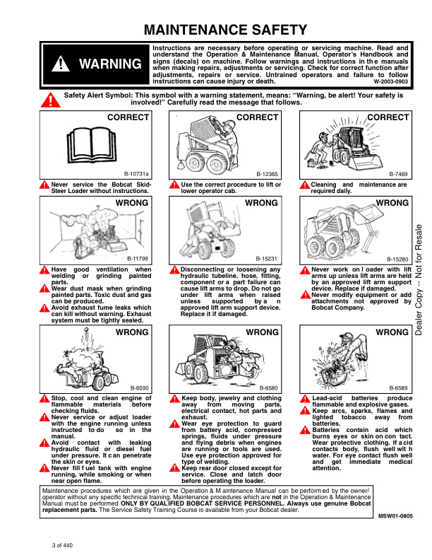
MAINTENANCE SAFETY
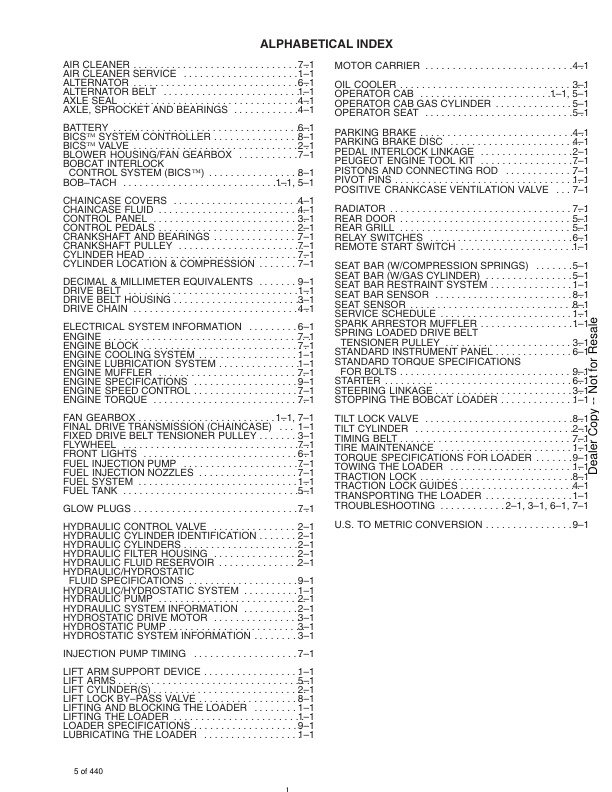
ALPHABETICAL INDEX
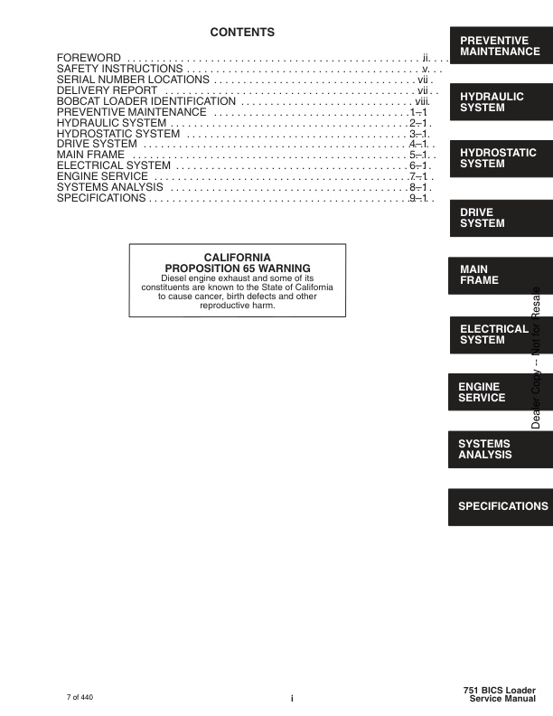
CONTENTS
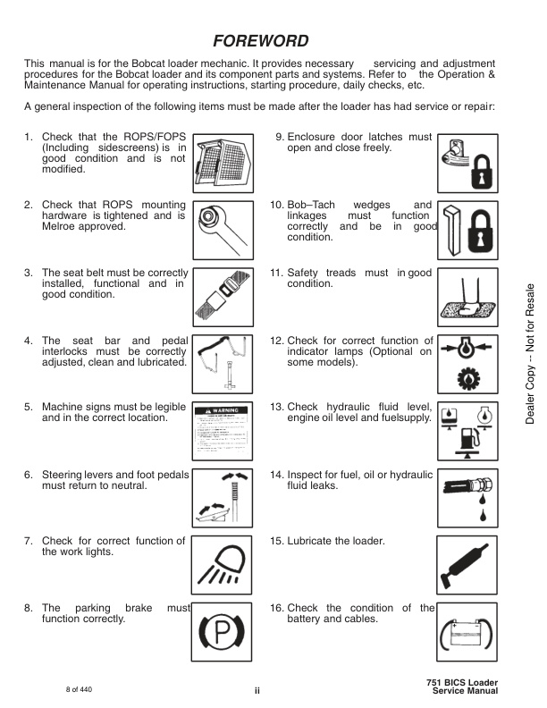
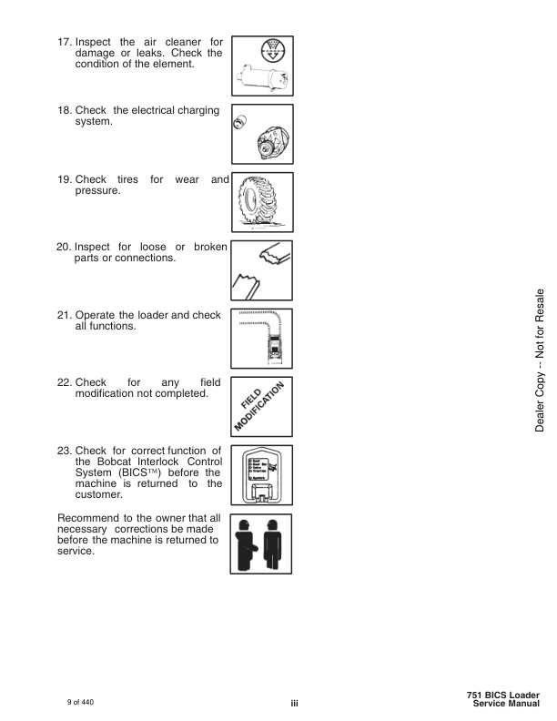
– FOREWORD
– SAFETY INSTRUCTIONS
– SERIAL NUMBER LOCATIONS
– LOADER SERIAL NUMBER
– ENGINE SERIAL NUMBER
– DELIVERY REPORT
– BOBCAT LOADER IDENTIFICATION
PREVENTIVE MAINTENANCE
– SERVICE SCHEDULE
– LIFTING AND BLOCKING THE LOADER
— Procedure
– TRANSPORTING THE LOADER
— Procedure
– TOWING THE LOADER
— Procedure
– STOPPING THE BOBCAT LOADER
– LIFTING THE LOADER
— Four Point Lift
— Single Point Lift
– LIFT ARM SUPPORT DEVICE
— Engaging The Lift Arm Support Device
— Disengaging The Lift Arm Support Device
– OPERATOR CAB
— Description
— Raising The Operator Cab
— Lowering The Operator Cab
— Emergency Exit
– SEAT BAR RESTRAINT SYSTEM
— Description (Foot Pedals)
— Seat Bar Inspection (Foot Pedals)
— Seat Bar Maintenance (Foot Pedals)
— Description (Hand Controls)
— Seat Bar Inspection (Hand Controls)
— Seat Bar Maintenance (Hand Controls)
– AIR CLEANER SERVICE
— Replacing Filter Element
– FUEL SYSTEM
— Fuel Specifications
— Filling the Fuel Tank
— Fuel Filter
— Removing Air From The Fuel System
– ENGINE LUBRICATION SYSTEM
— Checking Engine Oil
— Replacing Oil and Filter
– ENGINE COOLING SYSTEM
— Cleaning the Cooling System
— Checking the Coolant Level
— Replacing The Coolant
— Propylene Glycol
– ALTERNATOR BELT
— Adjusting The Alternator Belt
– BOB–TACH
– FAN GEARBOX
— Checking And Maintaining
– HYDRAULIC/HYDROSTATIC SYSTEM
— Checking And Adding Fluid
— Replacing Hydraulic/Hydrostatic Filter
— Replacing Hydraulic Fluid
— Hydraulic Reservoir Breather Cap
– SPARK ARRESTOR MUFFLER
— Cleaning Procedure
– TIRE MAINTENANCE
— Wheel Nuts
— Tire Rotation
— Tire Mounting
– FINAL DRIVE TRANSMISSION (CHAINCASE)
— Checking and Adding Oil
— Removing Oil From the Chaincase
– DRIVE BELT
— Adjusting The Drive Belt Equipped With The Fixed Drive Idler
— Adjusting The Drive Belt Equipped With The Spring Loaded Drive Ider
— Drive Belt Replacement
– LUBRICATION OF THE BOBCAT LOADER
— Procedure
– PIVOT PINS
– REMOTE START SWITCH
— Procedure
HYDRAULIC SYSTEM
– HYDRAULIC / HYDROSTATIC SCHEMATICS
– TROUBLESHOOTING
– HYDRAULIC SYSTEM INFORMATION
— Flare Connections
— O–ring Face Seal Connection
— Straight Thread O–ring Fitting
— Tubelines And Hoses
– LIFT CYLINDER(S)
— Checking The Lift Cylinder(s) For Internal Leakage
— Removal And Installation
– TILT CYLINDER
— Checking The Tilt Cylinder For Internal Leakage
— Removal And Installation
— Rod End Seal Replacement
– HYDRAULIC CYLINDER IDENTIFICATION
— Lift Cylinder Components
— Tilt Cylinder Components
– HYDRAULIC CYLINDERS
— Disassembly
— Assembly
– BICS™ VALVE (S/N 514713000 & Above, S/N 514911453 & Above)
— Removal
— Lift Arm By–Pass Orifice
— Disassembly
— Check Valve
— Disassembly
— Lock Valve
— Disassembly
— BICS™ Valve Solenoid
— Disassembly
— Assembly
— Lock Valve
— Assembly
— Check Valve
— Assembly
— Lift Arm By–Pass Orifice
— Assembly
— Installation
– CONTROL VALVE (S/N 514713000 & Above, S/N 514911453 & Above)
— Removal And Installation
— Identification Chart
— Disassembly
— Lift Base End Restrictor Disassembly
— Load Check Valve Disassembly
— Main Relief Valve Disassembly
— Port Relief Valve Disassembly
— Anti–Cavitation Disassembly
— Rubber Boot Disassembly
— Lift Spool And Detent Disassembly
— Tilt Spool And Centering Spring Disassembly
— Auxiliary Spool Disassembly
— Auxiliary Electric Solenoid Disassembly
— Port–Auxiliary Section Disassembly
— Cleaning and Inspection
— Port–Auxiliary Section Assembly
— Auxiliary Electric Solenoid Assembly
— Auxiliary Spool Assembly
— Tilt Spool And Centering Spring Assembly
— Lift Spool And Detent Assembly
— Rubber Boot Assembly
— Anti–Cavitation/Port Relief Valve Assembly
— Port Relief Valve Assembly
— Main Relief Valve Assembly
— Load Check Valve Assembly
— Spool Seal Installation
– CONTROL VALVE (S/N 514712999 & Below, S/N 514911452 & Below)
— Removal And Installation
— Checking The Main Relief Valve
— Main Relief Valve Adjustment
— Main Relief Valve Removal and Installation
— Identification Chart
— Disassembly And Assembly
— Load Check Valve
— Main Relief Valve
— Port Relief Valve
— Anti–Cavitation Valve
— Rubber Boot
— Lift Spool Detent
— Tilt Centering Spring
— Auxiliary Spool
— Auxiliary Electric Solenoid
— Inspection
— Identification And Installation Of Spool Seal
– HYDRAULIC PUMP
— Removal And Installation
— Checking The Output Of The Hydraulic Pump
— Disassembly And Assembly
— Inspection
— Identification
– HYDRAULIC FILTER HOUSING
— Removal And Installation
– HYDRAULIC FLUID RESERVOIR
— Removal And Installation
– CONTROL PEDALS
— Removal And Installation
— Pedal Adjustment
– PEDAL INTERLOCK LINKAGE
— Removal And Installation
— Adjustment
HYDROSTATIC SYSTEM
– TROUBLESHOOTING
— Chart
– HYDROSTATIC SYSTEM INFORMATION
— Replenishing Valve Function
— Checking Charge Pressure
– CONTROL PANEL
— Rubber Boot Replacement
— Removal and Installation
— Steering Shaft Removal and Installation
— Steering Shaft Disassembly and Assembly
— Steering Lever Removal and Installation
– STEERING LINKAGE
— Removal and Installation
— Steering Linkage Adjustment
— Steering Neutral Adjustment
– HYDROSTATIC DRIVE MOTOR
— Removal And Installation
— Identification
— Disassembly And Assembly
— Inspection
– HYDROSTATIC PUMP
— Removal And Installation
— Identification
— Disassembly And Assembly
— Inspection
— Swashplate Pre–Load
– DRIVE BELT HOUSING
— Removal And Installation
– SPRING LOADED DRIVE BELT TENSIONER PULLEY
— Removal And Installation
— Identification
— Disassembly
— Assembly
– FIXED DRIVE BELT TENSIONER PULLEY
— Removal And Installation
— Identification
— Disassembly
— Assembly
— Checking Pulley End Play
– OIL COOLER
— Removal and Installation
DRIVE SYSTEM
– PARKING BRAKE
— Removal And Installation
— Disassembly And Assembly
– PARKING BRAKE DISC
— Removal And Installation
– TRACTION LOCK GUIDES
— Disassembly
— Assembly
– CHAINCASE FLUID
— Removing Oil From The Chaincase
– CHAINCASE COVERS
— Center Chaincase Cover Removal And Installation
— Front Chaincase Cover Removal And Installation
— Rear Chaincase Cover Removal And Installation
– MOTOR CARRIER
— Shaft Seal Replacement
— Removal And Installation
— Disassembly
— Assembly
– AXLE SEAL
— Removal and Installation
– AXLE, SPROCKET AND BEARINGS
— Removal And Installation
– DRIVE CHAIN
— Removal And Installation
MAIN FRAME
– SEAT BAR (W/GAS CYLINDER)
— Removal And Installation
— Assembly
— Compressing The Gas Cylinder
– SEAT BAR (W/COMPRESSION SPRINGS)
— Removal And Installation
— Assembling Components
— Compression Spring Disassembly And Assembly
– OPERATOR CAB GAS CYLINDER
— Removal And Installation
— Disassembly And Assembly
– OPERATOR CAB
— Removal And Installation
– OPERATOR SEAT
— Removal And Installation
– BOB–TACH
— Removal And Installation
— Bob–Tach Lever And Wedge
— Bob–Tach Stops
– LIFT ARMS
— Removal And Installation
– REAR GRILL
— Removal And Installation
– FUEL TANK
— Removal And Installation
— Fuel Level Sender
– REAR DOOR
— Removal And Installation
— Hood Removal And Installation
— Bumper Removal And Installation
— Door Latch Removal And Installation
— Door Latch And Catch Adjustment
ELECTRICAL SYSTEM
– ELECTRICAL SCHEMATICS
– TROUBLESHOOTING
— Chart
– ELECTRICAL SYSTEM INFORMATION
— Description
— Fuse Location
– BATTERY
— Removal And Installation
— Servicing The Battery
— Using A Booster Battery (Jump Starting)
– ALTERNATOR
— Alternator Output Test
— Rectifier (Diode) Test
— Alternator Regulator Test
— Removal And Installation
— Adjusting The Alternator Belt
— Disassembly And Inspection
— Stator Continuity Test
— Stator Ground Test
— Rotor Continuity Test
— Rotor Ground Test
— Rectifier Continuity (Diode) Test
— Assembly
– STARTER
— Removal And Installation (228000–5210)
— Removal And Installation (228000–5740)
— Parts Identification (228000-5210)
— Disassembly (228000-5210)
— Inspection And Repair (228000-5210)
— No Load Test (228000-5210)
— Assembly (228000-5210)
— Parts Identification (228000-5740)
— Disassembly (228000–5740)
— Inspection And Repair (228000–5740)
— No Load Test (228000–5740)
— Assembly (228000–5740)
— STANDARD INSTRUMENT PANEL
— Removal And Installation
– FRONT LIGHTS
— Removal And Installation
– RELAY SWITCHES
— Location
— Glow Plug Preheat Relay
— Glow System In Operator Cab
— Troubleshooting The Glow Plug System
— Testing The Glow Plug Timer Relay
ENGINE SERVICE
– TROUBLESHOOTING
— Chart
– ENGINE SPEED CONTROL
— Removal And Installation
— Disassembly
– RADIATOR
— Removal And Installation
– ENGINE MUFFLER
— Removal And Installation
– BLOWER HOUSING/FAN GEARBOX
— Removal And Installation
— Tension Pulley Removal And Installation
— Blower Fan Disassembly And Assembly
– FAN GEARBOX
— Disassembly
— Long Housing
— Short Housing
— Assembly
— Long Housing
— Short Housing
— Checking Backlash
— Identification
– AIR CLEANER
— Removal And Installation
– ENGINE
— Removal And Installation
— Engine Mount Replacement
– FLYWHEEL
— Removal And Installation
— Flywheel Ring Gear
– INJECTION PUMP TIMING
— Checking Procedure
— Adjusting Injection Pump Timing
— Injection Pump Return Fitting
— Testing The Fuel Solenoid
— Idle Speed Setting
– TIMING BELT
— Removal
— Installation
– FUEL INJECTION PUMP
— Removal
— Installation
– FUEL INJECTOR NOZZLE
— Removal And Installation
— Checking The Injector Nozzle
– CYLINDER LOCATION & COMPRESSION
— Data
– GLOW PLUGS
— Removal And Installation
— Checking The Glow Plugs
– CYLINDER HEAD
— Removing The Cylinder Head
— Disassembly Of The Cylinder Head
— Removing The Combustion Chamber
— Removing The Heat Shield
— Installing The Heat Shield
— Servicing The Cylinder Head
— Checking The Valves
— Checking The Valve Springs
— Checking The Valve Guides
— Checking The Valve Seats
— Checking The Combustion Chamber
— Reassembly Of The Cylinder Head
— Installing The Cylinder Head
– ENGINE BLOCK
— Disassembly Of The Engine
— Assembly Of The Engine
– PISTONS AND CONNECTING RODS
— Disassembly And Assembly
— Checking The Piston
— Checking The Crankshaft
– CRANKSHAFT PULLEY
— Removal And Installation
– POSITIVE CRANKCASE VENTILATION VALVE
— Removal
— Installation
– PEUGEOT ENGINE TOOL KIT MEL1474 (Complete Kit)
– PEUGEOT ENGINE
— Chart
SYSTEMS ANALYSIS
– BOBCAT INTERLOCK CONTROL SYSTEM (BICS™)
— Inspecting The BICS Controller (Engine STOPPED –Key ON)
— Inspecting DeactivationOf The Auxiliary Hydraulics System (Engine STOPPED–Key ON)
— Inspecting The Seat And Seat Bar Sensors (EngineRUNNING)
— Inspecting The Traction Lock (Engine RUNNING)
— Inspecting The Lift Arm By–Pass Control
— Maintenance
— Troubleshooting Chart
— Troubleshoot Guide
— BICS CONTROLLER
— TRACTION LOCK
— SEAT SENSOR
— SEAT BAR SENSOR
— LIFT LOCK BY–PASS VALVE
– BICS™ SYSTEM CONTROLLER
— Removal And Installation
— Controller Test
– SEAT BAR SENSOR
— Removal And Installation
— Seat Bar Sensor Test
– SEAT SENSOR
— Removal And Installation
— Seat Sensor Test
– TRACTION LOCK
— Removal And Installation
– LIFT LOCK BY–PASS VALVE
— Removal And Installation (S/N 514712999 & Below,S/N 514911452 & Below)
— Disassembly and Assembly (S/N 514712999 & Below, S/N 514911452 & Below)
— Removal And Installation (S/N 514713000 & Above, S/N 514911453 & Above)
— Disassembly And Assembly (S/N 514713000 & Above, S/N 514911453 & Above)
– TILT LOCK VALVE
— Removal And Installation (S/N 514712999 & Below, S/N 514911452 & Below)
— Disassembly And Assembly (S/N 514712999 & Below, S/N 514911452 & Below)
SPECIFICATIONS
– SKID STEER LOADER SPECIFICATIONS
— PERFORMANCE
— CONTROLS
— ENGINE
— HYDRAULIC SYSTEM
— ELECTRICAL
— DRIVE SYSTEM
— CAPACITIES
— TIRES
— FLOOR PRESSURE
— VIBRATION DATA
– ENGINE SPECIFICATIONS
— Fuel Injection Nozzles
— Fuel Injection Pump
— Cylinder Head
— Valves
— Valve Springs
— Valve Guides
— Combustion Chamber
— Cylinders
— Piston Rings
— Pistons
— Connecting Rod
— Crankshaft
– TORQUE SPECIFICATIONS FOR LOADER
— Specifications
– HYDRAULIC/HYDROSTATIC FLUID SPECIFICATIONS
— Specifications
– STANDARD TORQUE SPECIFICATIONS FOR BOLTS
– DECIMAL AND MILLIMETER EQUIVALENTS
– U.S. TO METRIC CONVERSION
SERVICE MANUAL REVISIONS
– 751-001
– 751-002




Reviews
There are no reviews yet.