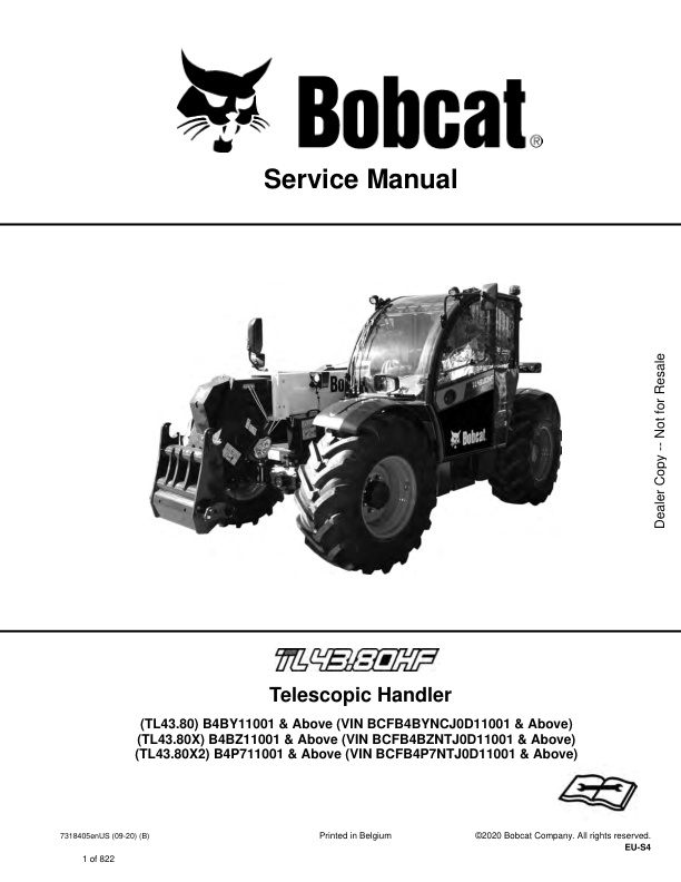
Bobcat TL43.80, TL43.80X, TL43.80X2 Telescopic Handler 7318405 (Preview)
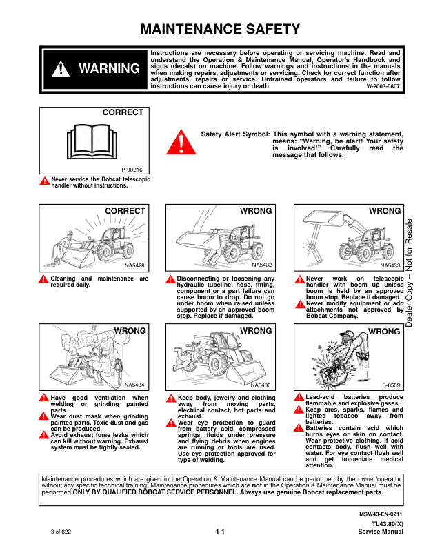
MAINTENANCE SAFETY
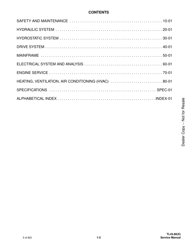
CONTENTS
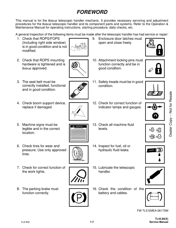
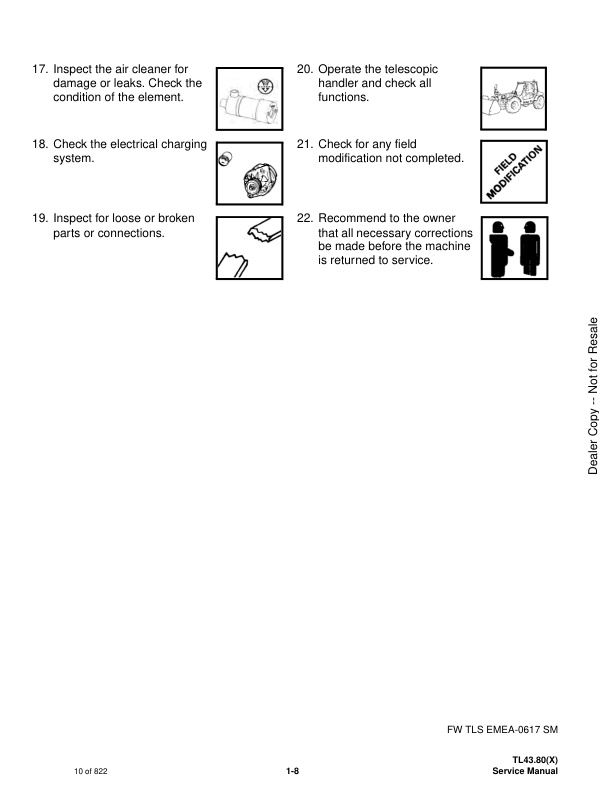
FOREWORD
FOREWORD
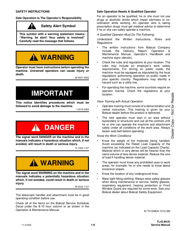
SAFETY INSTRUCTIONS
Safe Operation Is The Operator’s Responsibility
Safe Operation Needs A Qualified Operator
Avoid Silica Dust
Dismantling And Disposal
FIRE PREVENTION
Maintenance
Operation
Electrical
Hydraulic System
Fueling
Starting
Welding And Grinding
Fire Extinguishers
PUBLICATIONS AND TRAINING RESOURCES
SERIAL NUMBER LOCATION
Telescopic Handler Serial Number
Telescopic Handler Statutory Plate
Engine Serial Number
Other Serial Numbers
DELIVERY REPORT
BOBCAT TELESCOPIC HANDLER IDENTIFICATION
SAFETY AND MAINTENANCE
LIFTING AND BLOCKING THE TELESCOPIC HANDLER
Procedure
OPERATOR CAB
Description
Cab Door
Cab Door Window
Rear Cab Window
Cab Light
TRANSPORTING THE TELESCOPIC HANDLER ON A TRAILER
Loading And Unloading
Fastening
TOWING THE TELESCOPIC HANDLER
Procedure
SERVICE SCHEDULE
Maintenance Intervals
AIR CLEANER SERVICE
Replacing Filter Elements
COOLING SYSTEM
Cleaning
Checking Level
Removing And Replacing The Coolant
FUEL SYSTEM
Fuel Specifications
Biodiesel Blend Fuel
Filling The Fuel Tank
Fuel Pre-Filter
Fuel Filter
Removing Air From The Fuel System
ENGINE LUBRICATION SYSTEM
Checking And Adding Engine Oil
Engine Oil Chart
Removing And Replacing Oil And Filter
Removing And Replacing Oil Separator Filter
HYDRAULIC / HYDROSTATIC SYSTEM
Checking And Adding Fluid
Hydraulic / Hydrostatic Fluid
Removing And Replacing Hydraulic Fluid
Removing And Replacing Hydraulic / Hydrostatic Filters
Removing And Replacing Hydraulic Charge Filter
Fill / Breather Cap
Hydraulic Fluid Air Bleeding Procedure
Starter Procedure
AXLES (FRONT AND REAR)
Checking And Adding Oil (Planetary Carrier)
Removing And Replacing Oil (Planetary Carrier)
Checking And Adding Oil (Rear Differential)
Removing And Replacing Oil (Rear Differential)
Checking And Adding Oil (Front Differential)
Removing And Replacing Oil (Front Differential)
Checking And Adding Oil (Gearbox)
Removing And Replacing Oil (Gearbox)
LUBRICATING THE TELESCOPIC HANDLER
Lubrication Locations
ATTACHMENT CARRIER
Inspection And Maintenance
TIRE MAINTENANCE
Wheel Nuts
Rotating
Wheel Replacement
Mounting
Pressure
APPROVED BOOM STOP
Installing The Approved Boom Stop
Removing The Approved Boom Stop
ENGINE COVER
Opening And Closing
STOPPING THE ENGINE AND LEAVING THE TELESCOPIC HANDLER
Procedure
EMERGENCY EXIT
Rear Window
Right Rear Window
TELESCOPIC HANDLER STORAGE AND RETURN TO SERVICE
Storage
Return To Service
LIFTING THE TELESCOPIC HANDLER
Procedure
REMOTE START TOOL (SERVICE TOOL) KIT – 6987761
Remote Start Tool (Service Tool) – 7022042
Telescopic Handler Service Tool Harness – 6689747
Computer Service Tool Harness – 6689746
Remote Start Procedure
HYDRAULIC SYSTEM
HYDRAULIC / HYDROSTATIC SCHEMATICS
HYDRAULIC SYSTEM INFORMATION
Glossary Of Hydraulic / Hydrostatic Symbols
Troubleshooting Chart
Tightening Procedures
BOOM CYLINDER
Removal And Installation
Parts Identification
Disassembly
Assembly
SELF LEVELING (COMPENSATION) CYLINDER
Removal And Installation
Parts Identification
Disassembly
Assembly
EXTENSION (COMPENSATION) CYLINDER
Cylinder Group Removal And Installation
Upper Tubeline Removal And Installation
Extension Cylinder Removal And Installation
Tubeline Tray Disassembly
Parts Identification
Disassembly
Assembly
TILT CYLINDER
Removal And Installation
Parts Identification
Disassembly
Assembly
STEERING CYLINDER (FRONT / REAR)
Removal
Installation
Disassembly
Assembly
COLLECTOR BLOCK
Removal And Installation
Parts Identification
Disassembly And Assembly
SERVICE BRAKE VALVE
Removal And Installation
LS PISTON PUMP ELECTRONIC TORQUE CONTROL
LS Piston Pump Testing
Troubleshooting Chart (LS Piston Pump Testing)
Servo Piston Testing
Removal And Installation
Parts Identification
Disassembly And Assembly
FAN MOTOR
Description
Removal And Installation
Parts Identification (Single Speed Version) (Standard)
Disassembly And Assembly (Single Speed Version) (Standard)
Parts Identification (Variable Speed Version)
Disassembly And Assembly (Variable Speed Version)
HYDRAULIC FLUID TANK
Removal And Installation
STEERING UNIT
Removal And Installation
MAIN VALVE
Troubleshooting Chart (Controllers)
Valve Section Troubleshooting
Troubleshooting Chart (Main Valve)
Main Relief Valve Removal And Installation
Removal And Installation
Parts Identification
Disassembly And Assembly
End Housing Disassembly And Assembly
Auxiliary Valve Section Disassembly And Assembly
Telescoping Valve Section Disassembly And Assembly
Tilting Valve Section Disassembly And Assembly
Lifting Valve Section Disassembly And Assembly
Inlet-Outlet Valve Section Disassembly And Assembly
PORT RELIEF VALVES
Testing
Replacement Procedure
ACCUMULATORS
Accumulators Pressure Relief
Park / Service Brake Accumulator Removal And Installation
LS Pump Accumulator Removal And Installation
FAN PUMP
Description
Removal And Installation
Parts Identification
Disassembly And Assembly
POWER LIFT SYSTEM
Description
Removing And Installing The Self Leveling Valve
Removing And Installing The Power Lift Valve
TRAILER BRAKE VALVE
Description
Removal And Installation
BOOM SUSPENSION AND FLOAT SYSTEM
Boom Suspension Functional Description
Boom Float Functional Description
Removing And Installing The Boom Suspension Valve
HYDROSTATIC SYSTEM
HYDROSTATIC SYSTEM INFORMATION
Troubleshooting Chart
Replenishing Valve Function
Drive Component Location
Test Coupler Location
OIL COOLER
Description
HYDROSTATIC DRIVE MOTOR
Removal And Installation
Parts Identification
Disassembly
Inspection
Assembly
HYDROSTATIC PUMP
Removal And Installation
Parts Identification
Shaft Disassembly
Relief Valves Disassembly And Assembly
Charge Pump Disassembly
Piston Pump Disassembly
Solenoid Block Disassembly
Inspection
Piston Pump Assembly
Charge Pump Assembly
Solenoid Block Assembly
Shaft Assembly
CHARGE PRESSURE
Description
Testing And Adjusting
MULTIFUNCTION VALVES
Description
Testing
DRIVE SYSTEM
DRIVE SYSTEM TROUBLESHOOTING
Chart
AXLE AND DIFFERENTIAL (FRONT)
Description
Planetary Carrier And Drive Axle Parts Identification
Planetary Carrier Disassembly
Steering Knuckle Parts Identification
Steering Knuckle Disassembly
Drive Axle Disassembly
Brake Group Parts Identification
Brake Group Disassembly
Differential And Pinion Group Parts Identification
Differential Disassembly
Pinion Group Disassembly
Pinion Group Assembly
Differential Assembly
Brake Group Assembly
Drive Axle Assembly
Steering Knuckle Assembly
Planetary Carrier Assembly
AXLE AND DIFFERENTIAL (REAR)
Description
Planetary Carrier And Drive Axle Parts Identification
Planetary Carrier Disassembly
Steering Knuckle Parts Identification
Steering Knuckle Disassembly
Differential And Pinion Group Parts Identification
Differential Disassembly
Pinion Group Disassembly
Pinion Group Assembly
Differential Assembly
Steering Knuckle Assembly
Planetary Carrier Assembly
FRONT AXLE
Removal And Installation
AXLE TOE-IN
Adjustment
STEERING ANGLE ADJUSTMENT
Adjustment
PARK BRAKE
Releasing The Brake For Towing
Adjustment
Brake Cylinder Removal
Brake Cylinder Disassembly And Assembly
Brake Disc Removal And Installation
Brake Cylinder Installation
GEARBOX
Removal And Installation
Parts Identification
Disassembly
Assembly
GEARBOX SHIFTING CONTROL CYLINDER
Removal
Parts Identification
Disassembly
Assembly
Installation
DRIVESHAFT
Rear Driveshaft Removal And Installation
Front Driveshaft Removal And Installation
SERVICE BRAKE
Description
Bleeding The Brake Circuit
REAR AXLE
Removal And Installation
MAINFRAME
OPERATOR CAB
Removal And Installation
OPERATOR SEAT
Removal And Installation
FIXED BOOM
Removal
Installation
INNER BOOM
Removal And Installation
WEAR PADS (FRONT)
Boom Wear Pad Checking
Removal And Installation
WEAR PADS (REAR)
Boom Wear Pad Checking
Removal And Installation
ENGINE COVER
Gas Cylinder Removal And Installation
Removal And Installation
FUEL TANK
Removal And Installation
ATTACHMENT CARRIER (QUICK-TACH)
Removal And Installation
ATTACHMENT CARRIER (MER-TACH)
Removal And Installation
Setting Up The Attachment
COUNTERWEIGHT
Removal And Installation
FENDER
Removal And Installation
STEERING COLUMN COVER
Removal And Installation
DASH COVER
Removal And Installation
JOYSTICK PANEL
Removal And Installation
ELECTRICAL SYSTEM AND ANALYSIS
ELECTRICAL SCHEMATICS
ELECTRICAL SYSTEM INFORMATION
Glossary Of Electrical Symbols
Cab Harness Connectors
Mainframe Harness Connectors
Engine Bay Harness Connectors
Engine Bay Harness Connectors
DEF Harness Connectors
Engine Harness Connectors
Troubleshooting Chart
Description
Fuses And Relay Location / Identification
BATTERY
Battery Maintenance
Using A Booster Battery (Jump Starting)
Removing And Installing The Battery
ALTERNATOR
Belt Adjustment
Belt Checking
Belt Replacement
Removal And Installation
STARTER
Testing
Removal And Installation
LIGHTS
Rear Light Removal And Installation
Front Light Removal And Installation
Rear Work Light Removal And Installation
SIGNAL LEVER
Removal And Installation
DISPLAY
Removal And Installation
INSTRUMENT PANELS
Right Instrument And Indicator Panel Removal And Installation
Left Instrument Panel Removal And Installation
BOOM ANGLE SENSOR
Description
Removal And Installation
FRONT WIPER MOTOR
Removal And Installation
TOP WIPER MOTOR
Removal And Installation
REAR WIPER MOTOR
Removal And Installation
SERVICE BRAKE PEDAL ASSEMBLY
Removal And Installation
INCHING SENSOR
Description
Removal And Installation
EMERGENCY BRAKE
Description
SERVICE PC (LAPTOP COMPUTER)
Connecting Remote Start Tool (Service Tool) – 6987761
FUEL LEVEL SENDER
Removal And Installation
JOYSTICK
Removal And Installation
LLMI / LLMC SYSTEM
System Components Identification
Longitudinal Load Moment Indicator (LLMI) Description
Longitudinal Load Moment Controller (LLMC)
Longitudinal Load Moment Controller (LLMC) Override Switch
LLMS Removal
LLMS Installation
MAINTENANCE CLOCK
Description
Setup
Reset
CONTROLLERS
Description
Gateway Controller
Drive Controller
Workgroup Controller
Display Controller
LLMI Controller
LLMC Controller
Engine Controller
Dosing Controller
RETRACT SENSOR
Removal And Installation
Adjustment
AUTOMATIC PARK BRAKE
Description
CALIBRATION
Calibrating The Hydrostatic Pump
Calibrating The Boom Angle Sensor
Calibrating The Inching Sensor
Calibrating The LLMC System
LLMC Calibration Test
LLMI / LLMC System Failure Reports
ENGINE SERVICE
ENGINE
Description
Sensor Locations
Troubleshooting
Removal And Installation
ENGINE BAY ASSEMBLY
Removal And Installation
ENGINE SPEED CONTROL
Removal And Installation
EXHAUST PIPE
Removal And Installation
AIR CLEANER
Housing Removal And Installation
COOLING SYSTEM
Hydraulic Oil Cooler / Intercooler / Radiator Removal And Installation
Expansion Tank Removal And Installation
Cooling System Check
Cooling System Inspection
SELECTIVE CATALYTIC REDUCTION (SCR) SYSTEM
Description
Diesel Exhaust Fluid (DEF) / AdBlue® Level
DeSOX Process
SCR System Codes
Diesel Exhaust Fluid (DEF) / AdBlue® Unsatisfactory Quality
SCR System Component Tampering
EGR Impeded
Diesel Exhaust Fluid (DEF) / AdBlue® Dosing Interruption
Removal And Installation
Dosing Module Removal And Installation
DIESEL OXIDATION CATALYST (DOC)
Removal And Installation
EXHAUST GAS RECIRCULATION (EGR) SYSTEM
Description
TURBOCHARGER
Description
DIESEL EXHAUST FLUID (DEF) TANK
Removal And Installation
DEF Tank Fan Removal And Installation
Coolant Valve Removal And Installation
Dosing Control Unit (DCU) Removal And Installation
Supply Module Removal And Installation
Supply Module Filter Removal And Installation
FUEL COOLER
Removal And Installation
HEATING, VENTILATION, AIR CONDITIONING (HVAC)
AIR CONDITIONING SYSTEM FLOW
Description
Chart
Components
Safety Equipment
REGULAR MAINTENANCE
Filters
Air Conditioning Belt Adjustment
Belt Replacement
Cleaning The Condenser
Air Conditioning Lubrication
Air Conditioning Service Chart
Evaporator / Heater Coil
A/C SYSTEM TROUBLESHOOTING
Blower Motor Does Not Operate
Blower Motor Operates Normally, But Air Flow Is Insufficient
Insufficient Cooling Although Air Flow And Compressor Operation Are Normal
The Compressor Does Not Operate At All, Or Operates Improperly
Gauge Pressure Related Troubleshooting
Temperature / Pressure Chart
Poor A/C Performance
HVAC Repair And Leaks
Electrical System
SYSTEM CHARGING AND RECLAMATION
Reclamation And Charging With Recovery / Charging Unit
COMPRESSOR
Removal And Installation
Oil
Oil Check
Clutch Disassembly And Assembly
CONDENSER
Removal And Installation
RECEIVER / DRIER
Removal And Installation
PRESSURE SWITCH
Removal And Installation
EVAPORATOR / HEATER UNIT
Removal And Installation
THERMOSTAT
Description
Removal And Installation
EXPANSION VALVE
Removal And Installation
SPECIFICATIONS
(TL43.80(X)) TELESCOPIC HANDLER SPECIFICATIONS
Machine Dimensions
Performance
Weights
Engine
Controls
Drive System
Traction
Steering
Brakes
Fluid Capacities
Hydraulic System
Electrical System
Temperature Range
Altitude
Instrument Panel
Environmental
Visibility Diagrams
Visibility Diagrams For Light Material Buckets
Lifting
Tie Down
MACHINE TORQUE SPECIFICATIONS
Axle
Boom
Drive Box
Drive Motor
Engine
Hydraulic Pump
TORQUE SPECIFICATIONS FOR BOLTS
Torque for General SAE Bolts
Torque For General Metric Bolts
HYDRAULIC CONNECTION SPECIFICATIONS
O-ring Face Seal Connection
Straight Thread O-ring Fitting
Tubelines And Hoses
Flare Fitting
O-ring Flare Fitting
Port Seal Fitting
HYDRAULIC / HYDROSTATIC FLUID SPECIFICATIONS
Specifications
CONVERSIONS
Decimal And Millimeter Equivalent Chart
U.S. To Metric Conversion Chart
SERVICE TOOLS REQUIRED
Remote Start Tools
Hydraulic Tools
Drive Tools
Electrical Tools
Engine Tools
Special Drive Tools
ALPHABETICAL INDEX


There are no reviews yet.