AccuGrade® GPS (CD700)
– Angle Sensor – Calibrate – AS300 System
– Angle Sensor – Calibrate – PSC System
– Avoidance Zone
– Base Station
– Beeper
– Beeper
– Brightness (Display and Light Bar)
– CAN Data Link – Test
– Connector Contact Description
– Customer Supplied Radio
– Data Card
– Design Folder
– Diagnostic Capabilities
– Display Firmware Upgrade
– Display Language
– Display Registration and Activation
– Display Settings
– Display Units
– Electrical Connector – Inspect
– Electrical Power Supply
– Flashing Messages
– General Information
– General Information
– Glossary of Terms
– GPS Accuracy Mode
– Guidance Terms
– Light Bar
– Light Bar – Configure
– Light Bar Scale
– Machine Dimensions
– Machine Dimensions – Configure
– Machine Position – Display Messages
– Machine Radio
– Machine Type
– Machine Type – Configure
– Map Recording
– Modes of Operation
– Module – Replace – AccuGrade Display
– On-Grade Tolerance
– Operational Problems
– Operator Access
– Radio Utility
– Receiver
– Receiver Configuration
– Receiver Firmware Upgrade
– Root Folder
– Sensor Firmware Upgrade
– Service Tools
– Setup Menu
– Software Support Option
– Status Indicators
– System Components
– System Schematic
– Text Items
– Wireless Communication
– Wiring Harness (Open Circuit) – Test
– Wiring Harness (Short Circuit) – Test
Air Conditioning and Heating R134a for All Caterpillar Machines
– Refrigerant Compressor
– System Capacities for Refrigerant (Off-Highway Trucks)
– General Information
– Identifying the Refrigerant
– Identifying the Air Conditioning System
– Identifying the Heating System
– Refrigerant Expansion Valve System
– Refrigerant Orifice Tube System
– Refrigerant Compressor
– Refrigerant Condenser
– Refrigerant Receiver-Dryer
– Refrigerant Compressor
– Refrigerant Expansion Valve
– In-line Refrigerant Dryer
– Refrigerant Orifice Tube Assembly
– Evaporator Coil
– Refrigerant Accumulator
– Refrigerant Compressor Protection System
– Temperature Control
– Pressure Switch (Refrigerant)
– Cab Pressurization and Filtration System
– Condensate Drainage System
– Refrigerant Compressor
– Service Intervals
– Glossary of Terms
– Required Tools
– Machine Preparation for Troubleshooting
– General Troubleshooting Information
– General Troubleshooting Information
– Visual Inspection (Troubleshooting)
– Air Conditioning System Troubleshooting
– Heating System Troubleshooting
– Automatic Temperature Control System (ECM Controlled)
– Refrigerant Compressor
– Troubleshooting Heating and Air Conditioning Control System
– Troubleshooting Heating and Air Conditioning Control System
– Automatic Temperature Control Panel Troubleshooting – 584
– Troubleshooting Condensate Drainage System
– Machine Preparation for Testing and Adjusting
– Air Conditioning Performance – Test
– Refrigerant Leakage – Test
– Manifold Gauge Set (Refrigerant) – Install
– Refrigerant Recovery
– Refrigerant System – Flush
– Refrigerant Compressor
– Refrigerant Oil – Test
– Refrigerant Compressor – Test
– Refrigerant System – Evacuate
– Refrigerant System – Charge
– Manifold Gauge Set (Refrigerant) – Remove
– Compressor Protection System – Test
– Electronic Heat Control – Test
– Heater Performance – Test
– Heating and Air Conditioning Service Publications
– General Information
– Refrigerant Compressor
– Machine Preparation for Disassembly and Assembly
– Air Conditioner Lines – Remove and Install
– Refrigerant Compressor – Remove and Install
– Refrigerant Accumulator – Remove and Install
– Refrigerant Expansion Valve – Remove and Install
– Refrigerant Receiver-Dryer – Remove and Install
– In-Line Refrigerant Dryer – Remove and Install
– Refrigerant Orifice Tube Assembly – Remove and Install
– Refrigerant Compressor
– System Capacities for Refrigerant (Motor Graders)
– System Capacities for Refrigerant (Off-Highway Trucks) –
– Refrigerant Compressor
Disassembly and Assembly 324D and 325D Excavators Engine Supplement
– Aftercooler – Remove and Install
– Air Cleaner – Remove and Install
– Air Inlet Cover – Remove and Install
– Alternator – Remove and Install
– Battery – Remove and Install
– Belt Tightener – Remove and Install
– Crankshaft Front Seal – Install
– Crankshaft Front Seal – Remove
– Crankshaft Vibration Damper and Pulley – Remove and Install
– Electric Starting Motor – Remove and Install
– Engine – Install
– Engine – Remove
– Engine Electronic Control – Remove and Install
– Engine Front Mount – Install
– Engine Front Mount – Remove
– Engine Oil Cooler – Remove and Install
– Engine Oil Filter and Oil Filter Base – Remove and Install
– Engine Oil Pump – Remove and Install
– Engine Rear Mount – Install
– Engine Rear Mount – Remove
– Fan Guard – Remove and Install
– Flywheel – Remove and Install
– Fuel Filter (Secondary) and Fuel Filter Base – Remove and
– Fuel Priming Pump and Primary Filter (Water Separator) –
– Hood – Remove and Install
– Hydraulic Oil Cooler – Remove and Install
– Hydraulic System Pressure – Release
– Muffler – Remove and Install
– Oil Pan – Remove and Install – Engine in Chassis
– Radiator – Remove and Install
– Radiator and Hydraulic Oil Cooler – Install
– Radiator and Hydraulic Oil Cooler – Remove
– Refrigerant Compressor – Remove and Install
– Refrigerant Condenser – Remove and Install
– Refrigerant Receiver-Dryer – Remove and Install
– Reversible Fan – Assemble
– Reversible Fan – Disassemble
– Reversible Fan – Install
– Reversible Fan – Remove
– System Pressure – Release
– Turbocharger – Remove and Install
– Unit Injector Hydraulic Pump and Fuel Transfer Pump –
– Unit Injector Hydraulic Pump and Fuel Transfer Pump –
– Water Pump – Install
– Water Pump – Remove
– Water Temperature Regulator – Remove and Install
Disassembly and Assembly 324D and 325D Forest Machines Machine Systems
– Accumulator (Hydraulic Pilot) – Remove and Install
– Blower Motor (Air Conditioner, Heater) – Remove and Install
– Boom – Install
– Boom – Remove
– Boom Bearings and Seals – Remove and Install
– Boom Cylinder – Remove and Install
– Cab – Install
– Cab – Remove
– Cab Tilt Cylinder – Remove and Install
– Control Manifold (Pilot Oil) – Assemble – NFC Limit Valve
– Control Manifold (Pilot Oil) – Disassemble – NFC Limit Valve
– Control Manifold (Pilot Oil) – Install
– Control Manifold (Pilot Oil) – Install – NFC Limit Valve
– Control Manifold (Pilot Oil) – Remove
– Control Manifold (Pilot Oil) – Remove – NFC Limit Valve
– Counterbalance Valve (Travel) – Assemble
– Counterbalance Valve (Travel) – Disassemble
– Counterbalance Valve (Travel) – Install
– Counterbalance Valve (Travel) – Remove
– Counterweight – Remove and Install
– Drift Reduction Valve (Boom) – Assemble
– Drift Reduction Valve (Boom) – Disassemble
– Drift Reduction Valve (Boom) – Install
– Drift Reduction Valve (Boom) – Remove
– Drift Reduction Valve (Stick) – Assemble
– Drift Reduction Valve (Stick) – Disassemble
– Drift Reduction Valve (Stick) – Install
– Drift Reduction Valve (Stick) – Remove
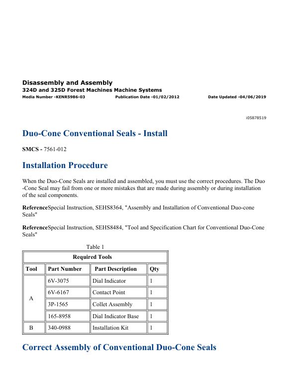
– Duo-Cone Conventional Seals – Install
– Evaporator Coil – Remove and Install
– Final Drive – Assemble
– Final Drive – Assemble
– Final Drive – Disassemble
– Final Drive – Disassemble
– Final Drive – Install
– Final Drive – Remove
– Front Idler – Assemble
– Front Idler – Disassemble
– Front Idler, Recoil Spring and Hydraulic Track Adjuster –
– Front Idler, Recoil Spring and Hydraulic Track Adjuster –
– Fuel Tank – Install
– Fuel Tank – Remove
– Gear Pump (Auxiliary) – Assemble
– Gear Pump (Auxiliary) – Disassemble
– Gear Pump (Auxiliary) – Install
– Gear Pump (Auxiliary) – Remove
– Gear Pump (Pilot) – Assemble
– Gear Pump (Pilot) – Disassemble
– Gear Pump (Pilot) – Install
– Gear Pump (Pilot) – Remove
– Heater Core – Remove and Install
– Heating and Air Conditioning Unit – Install
– Heating and Air Conditioning Unit – Remove
– Hydraulic Tank and Filter – Install
– Hydraulic Tank and Filter – Remove
– Main Control Valve – Assemble
– Main Control Valve – Disassemble
– Main Control Valve – Install
– Main Control Valve – Remove
– Main Hydraulic Pump – Assemble
– Main Hydraulic Pump – Disassemble
– Main Hydraulic Pump and Pump Drive Coupling – Install
– Main Hydraulic Pump and Pump Drive Coupling – Remove
– Oil Filter (Hydraulic, Return) – Install
– Oil Filter (Hydraulic, Return) – Remove
– Pilot Valve (Joystick) – Assemble
– Pilot Valve (Joystick) – Disassemble
– Pilot Valve (Joystick) – Install
– Pilot Valve (Joystick) – Remove
– Pilot Valve (Travel) – Assemble
– Pilot Valve (Travel) – Disassemble
– Pilot Valve (Travel) – Install
– Pilot Valve (Travel) – Remove
– Pressure Reducing Valve (Implement and Swing Priority) –
– Pressure Reducing Valve (Implement and Swing Priority) –
– Pressure Reducing Valve (Implement and Swing Priority) –
– Pressure Reducing Valve (Implement and Swing Priority) –
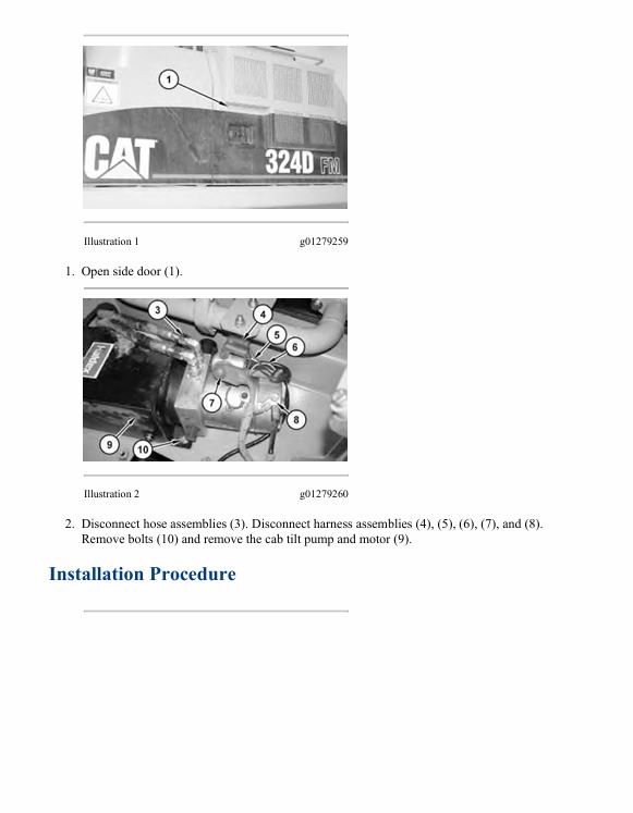
– Pump and Motor (Cab Tilt) – Remove and Install
– Pump Drive Coupling – Remove and Install
– Recoil Spring – Assemble
– Recoil Spring – Disassemble
– Recoil Spring – Disassemble
– Relief Valve (Pilot) – Remove and Install
– Seat – Remove and Install
– Shuttle Valve – Assemble – Straight Travel
– Shuttle Valve – Disassemble – Straight Travel
– Shuttle Valve – Install – Pilot
– Shuttle Valve – Install – Straight Travel
– Shuttle Valve – Remove – Pilot
– Shuttle Valve – Remove – Straight Travel
– Solenoid Valve (Hydraulic Lockout) – Remove and Install
– Solenoid Valve (Swing Brake) – Remove and Install
– Solenoid Valve (Travel Speed) – Remove and Install
– Solenoid Valve (WORK TOOL, 4-FUNCTION) – Assemble
– Solenoid Valve (WORK TOOL, 4-FUNCTION) – Disassemble
– Solenoid Valve (WORK TOOL, 4-FUNCTION) – Install
– Solenoid Valve (WORK TOOL, 4-FUNCTION) – Remove
– Sprocket – Remove and Install
– Stick – Install
– Stick – Remove
– Stick Bearings and Seals – Install
– Stick Bearings and Seals – Remove
– Stick Cylinder – Remove and Install
– Swing Cushion Valve – Assemble
– Swing Cushion Valve – Disassemble
– Swing Cushion Valve – Install
– Swing Cushion Valve – Remove
– Swing Drive – Assemble
– Swing Drive – Disassemble
– Swing Drive – Install
– Swing Drive – Remove
– Swing Gear and Bearing – Install
– Swing Gear and Bearing – Remove
– Swing Motor – Assemble
– Swing Motor – Disassemble
– Swing Motor – Install
– Swing Motor – Remove
– Swivel – Assemble
– Swivel – Disassemble
– Swivel – Install
– Swivel – Remove
– System Pressure – Release
– System Pressure – Release
– Track – Connect
– Track – Connect – PPR2
– Track – Separate
– Track – Separate – PPR2
– Track Adjuster – Assemble
– Track Adjuster – Disassemble
– Track Carrier Roller – Install
– Track Carrier Roller – Remove
– Track Roller – Install
– Track Roller – Remove
– Travel Motor – Assemble
– Travel Motor – Disassemble
– Travel Motor – Install
– Travel Motor – Remove
– Undercarriage Frame – Install
– Undercarriage Frame – Remove
– Window Wiper Motor – Remove and Install
Disassembly and Assembly C7 Engines for Caterpillar Built Machines
– Air Inlet Heater Solenoid – Remove and Install
– Alternator – Remove and Install
– Atmospheric Pressure Sensor – Remove and Install
– Bearing Clearance – Check
– Camshaft – Install
– Camshaft – Remove
– Camshaft Bearings – Remove and Install
– Camshaft Gear – Remove and Install
– Camshaft Idler Gear – Remove and Install
– Connecting Rod Bearings – Install
– Connecting Rod Bearings – Remove
– Coolant Temperature Sensor – Remove and Install
– Crankshaft – Install
– Crankshaft – Remove
– Crankshaft Front Seal – Install
– Crankshaft Front Seal – Remove
– Crankshaft Gear – Remove and Install
– Crankshaft Main Bearings – Install
– Crankshaft Main Bearings – Remove
– Crankshaft Rear Seal – Install
– Crankshaft Rear Seal – Remove
– Crankshaft Rear Seal Carrier – Remove and Install
– Cylinder Head – Install
– Cylinder Head – Remove
– Electric Starting Motor – Remove and Install
– Electronic Control Module – Remove and Install
– Engine Oil Filter Base – Assemble
– Engine Oil Filter Base – Disassemble
– Engine Oil Filter Base and Oil Cooler – Install
– Engine Oil Filter Base and Oil Cooler – Remove
– Engine Oil Pan – Remove and Install
– Engine Oil Pressure Sensor – Remove and Install
– Engine Oil Pump – Assemble
– Engine Oil Pump – Disassemble
– Engine Oil Pump – Install
– Engine Oil Pump – Remove
– Exhaust Manifold – Remove and Install
– Fan Drive Mounting Group – Remove and Install
– Flywheel – Install
– Flywheel – Remove
– Flywheel Housing – Remove and Install
– Front Cover – Remove and Install
– Fuel Filter Base – Remove and Install
– Fuel Pressure Sensor – Remove and Install
– Fuel Transfer Pump – Install
– Fuel Transfer Pump – Remove
– Housing (Front) – Install
– Housing (Front) – Remove
– Injection Actuation Pressure Sensor – Remove and Install
– Inlet Air Temperature Sensor – Remove and Install
– Inlet and Exhaust Valve Guides – Remove and Install
– Inlet and Exhaust Valve Seat Inserts – Remove and Install
– Inlet and Exhaust Valves – Remove and Install
– Inlet Manifold – Install
– Inlet Manifold – Remove
– Lifter Group – Remove and Install
– Piston Cooling Jets – Remove and Install
– Pistons and Connecting Rods – Assemble
– Pistons and Connecting Rods – Disassemble
– Pistons and Connecting Rods – Install
– Pistons and Connecting Rods – Remove
– Rocker Shaft – Assemble
– Rocker Shaft – Disassemble
– Rocker Shaft and Pushrod – Install
– Rocker Shaft and Pushrod – Remove
– Speed/Timing Sensor – Remove and Install
– Turbocharger – Install
– Turbocharger – Remove
– Turbocharger Outlet Pressure Sensor – Remove and Install
– Unit Injector – Install
– Unit Injector – Remove
– Unit Injector Hydraulic Pump – Install
– Unit Injector Hydraulic Pump – Remove
– Unit Injector Sleeve – Install
– Unit Injector Sleeve – Remove
– Valve Mechanism Cover – Remove and Install
– Valve Mechanism Cover Base – Remove and Install
– Vibration Damper and Pulley – Remove and Install
– Water Pump – Assemble
– Water Pump – Disassemble
– Water Pump – Install
– Water Pump – Remove
– Water Temperature Regulator – Remove and Install
Mobile Hydraulic Power Units Machine
– Calibration
– Charging System – Test
– Diagnostic Capabilities
– Diagnostic Code List
– Diagnostic Operation
– Electrical Component and Connector Locations
– Electrical Connector – Inspect
– Electronic Control Module (ECM) – Configure
– Electronic Control Module (ECM) – Flash Program
– Electronic Control Module (ECM) – Replace
– Electronic Control Module (Machine)
– Emerging Symptom Information
– General Information
– General Information
– Glossary of Electrical Terms
– Governor Actuator – Replace
– MID 039 – CID 0041 – FMI 06
– MID 039 – CID 0096 – FMI 04
– MID 039 – CID 0096 – FMI 05
– MID 039 – CID 0110 – FMI 04
– MID 039 – CID 0110 – FMI 09
– MID 039 – CID 0167 – FMI 12
– MID 039 – CID 0168 – FMI 05
– MID 039 – CID 0171 – FMI 03
– MID 039 – CID 0171 – FMI 04
– MID 039 – CID 0190 – FMI 08
– MID 039 – CID 0246 – FMI 12
– MID 039 – CID 0247 – FMI 12
– MID 039 – CID 0248 – FMI 12
– MID 039 – CID 0254 – FMI 12
– MID 039 – CID 0262 – FMI 06
– MID 039 – CID 0271 – FMI 06
– MID 039 – CID 0291 – FMI 03
– MID 039 – CID 0291 – FMI 05
– MID 039 – CID 0291 – FMI 06
– MID 039 – CID 0362 – FMI 03
– MID 039 – CID 0362 – FMI 05
– MID 039 – CID 0362 – FMI 06
– MID 039 – CID 0374 – FMI 03
– MID 039 – CID 0374 – FMI 05
– MID 039 – CID 0374 – FMI 06
– MID 039 – CID 0444 – FMI 03
– MID 039 – CID 0444 – FMI 06
– MID 039 – CID 0544 – FMI 08
– MID 039 – CID 0581 – FMI 03
– MID 039 – CID 0581 – FMI 05
– MID 039 – CID 0581 – FMI 06
– MID 039 – CID 0586 – FMI 05
– MID 039 – CID 0586 – FMI 12
– MID 039 – CID 0588 – FMI 09
– MID 039 – CID 0590 – FMI 09
– MID 039 – CID 0598 – FMI 03
– MID 039 – CID 0598 – FMI 05
– MID 039 – CID 0598 – FMI 06
– MID 039 – CID 0600 – FMI 04
– MID 039 – CID 0735 – FMI 03
– MID 039 – CID 0735 – FMI 05
– MID 039 – CID 0735 – FMI 06
– MID 039 – CID 1129 – FMI 03
– MID 039 – CID 1129 – FMI 04
– MID 039 – CID 1129 – FMI 08
– MID 039 – CID 1130 – FMI 03
– MID 039 – CID 1130 – FMI 04
– MID 039 – CID 1130 – FMI 08
– MID 039 – CID 1160 – FMI 03
– MID 039 – CID 1160 – FMI 05
– MID 039 – CID 1160 – FMI 06
– MID 039 – CID 1178 – FMI 03
– MID 039 – CID 1178 – FMI 04
– MID 039 – CID 1178 – FMI 08
– MID 039 – CID 1522 – FMI 03
– MID 039 – CID 1522 – FMI 05
– MID 039 – CID 1522 – FMI 06
– MID 039 – CID 1523 – FMI 03
– MID 039 – CID 1523 – FMI 05
– MID 039 – CID 1523 – FMI 06
– MID 039 – CID 1525 – FMI 03
– MID 039 – CID 1525 – FMI 05
– MID 039 – CID 1525 – FMI 06
– MID 039 – CID 1590 – FMI 03
– MID 039 – CID 1590 – FMI 05
– MID 039 – CID 1590 – FMI 06
– MID 039 – CID 1593 – FMI 03
– MID 039 – CID 1593 – FMI 05
– MID 039 – CID 1593 – FMI 06
– MID 039 – CID 1594 – FMI 03
– MID 039 – CID 1594 – FMI 05
– MID 039 – CID 1594 – FMI 06
– MID 039 – CID 1595 – FMI 03
– MID 039 – CID 1595 – FMI 05
– MID 039 – CID 1595 – FMI 06
– MID 039 – CID 1596 – FMI 03
– MID 039 – CID 1596 – FMI 05
– MID 039 – CID 1596 – FMI 06
– MID 039 – CID 1597 – FMI 03
– MID 039 – CID 1597 – FMI 05
– MID 039 – CID 1597 – FMI 06
– MID 039 – CID 1598 – FMI 03
– MID 039 – CID 1598 – FMI 05
– MID 039 – CID 1598 – FMI 06
– MID 039 – CID 1609 – FMI 03
– MID 039 – CID 1609 – FMI 04
– MID 039 – CID 1609 – FMI 08
– MID 039 – CID 1657 – FMI 03
– MID 039 – CID 1657 – FMI 04
– MID 039 – CID 1657 – FMI 08
– MID 039 – CID 1658 – FMI 03
– MID 039 – CID 1658 – FMI 04
– MID 039 – CID 1658 – FMI 08
– MID 039 – CID 1665 – FMI 03
– MID 039 – CID 1665 – FMI 05
– MID 039 – CID 1665 – FMI 06
– MID 039 – CID 1666 – FMI 03
– MID 039 – CID 1666 – FMI 05
– MID 039 – CID 1666 – FMI 06
– MID 039 – CID 1931 – FMI 03
– MID 039 – CID 1931 – FMI 05
– MID 039 – CID 1931 – FMI 06
– MID 039 – CID 2265 – FMI 03
– MID 039 – CID 2265 – FMI 04
– MID 039 – CID 2265 – FMI 08
– MID 039 – CID 2266 – FMI 03
– MID 039 – CID 2266 – FMI 04
– MID 039 – CID 2266 – FMI 08
– MID 039 – CID 2275 – FMI 03
– MID 039 – CID 2275 – FMI 06
– MID 039 – CID 2280 – FMI 03
– MID 039 – CID 2300 – FMI 09
– MID 039 – CID 2420 – FMI 03
– MID 039 – CID 2420 – FMI 05
– MID 039 – CID 2420 – FMI 06
– MID 039 – CID 2425 – FMI 03
– MID 039 – CID 2425 – FMI 04
– MID 039 – CID 2425 – FMI 13
– Related Components
– Sensors
– Service Tools
– Solenoids
– Speed Sensor – Adjust
– Switches
– Symptom Troubleshooting
– System Operation
– System Schematic
– Using Caterpillar Electronic Technician to Determine
– Using the Operator Monitor to Determine Diagnostic Codes
– Wiring Harness (Open Circuit) – Test
– Wiring Harness (Short Circuit) – Test
Schematic Caterpillar 311D, 312D, 315D, 319D, 320D, 323D, 324D, 325D, 329D, 330D and 336D Excavators Electrical System
Schematic Caterpillar 324D and 325D Forest Machine Electrical System
– Feature
– Cover Page
– Information
– Component Location
– Volume 1 of 3 – Engine and Chassis
– Volume 2 of 3 – Operator Station
– Volume 3 of 3 – Operator Station, Cab and Engine
– Connector Location
– Volume 1 of 3 – Engine and Chassis
– Volume 2 of 3 – Operator Station
– Volume 3 of 3 – Operator Station, Cab and Engine
– CID/MID/FMI
– Page 1 of 2
– Page 2 of 2
– Specifications and Related Manuals
– Wire Description
– Volume 1 of 3 – Engine and Chassis
– Page 1 of 3
– Page 2 of 3
– Page 3 of 3
– Volume 2 of 3 – Operator Station
– Page 1 of 2
– Page 2 of 2
– Volume 3 of 3 – Operator Station, Cab and Engine
– Standard Electrical
– Schematics
– Volume 1 of 3 – Engine and Chassis
– Volume 2 of 3 – Operator Station
– Volume 3 of 3 – Operator Station, Cab and Engine
– Machine Views
– Machine Harness Connector and Component Locations Volume 1
– Machine Harness Connector and Component Locations Volume 2
– Machine Harness Connector and Component Locations Volume 3
– Cab View Harness Connector and Compoent Locations Volume 1
– Cab View Harness Connector and Compoent Locations Volume 2
– Cab View Harness Connector and Compoent Locations Volume 3
– Engine View Harness Connector and Component Locations Volume 3
Schematic Caterpillar 325D And 330D FM Excavator Electrical System – Attachment
Schematic Caterpillar 325D Forest Machine Hydraulic System
– Features
– Cover Page
– Information
– Component Location
– Tap Location
– Fluid Power Symbols
– Electrical Symbols
– Schematic
– Machine Views
– Machine Component Locations
– Butt-N-Top Control Valve Circuit
– Control Manifold
– Main Control Valve
– Main Pump and Filter Circuits
– Tilt and Grapple Control Circuit
Specifications 325D Forest Machine Machine System
– Accumulator (Pilot)
– Air Cleaner – Precleaner
– Air Conditioner Lines
– Air Conditioner Lines
– Air Conditioner Lines – 1219.2 mm (48.00 inch) Cab Riser
– Boom – 5.6 m (18.37 ft)
– Boom – 6.15 m (20.177 ft)
– Boom – Log Loader
– Boom Cylinder
– Boom Cylinder
– Boom Cylinder
– Boom Cylinder Lines
– Boom Cylinder Lines
– Boom Cylinder Lines – Load Control Valve
– Boom Lines
– Boom Lines
– Boom Lines – Log Loader
– Bucket Cylinder
– Bucket Cylinder
– Bucket Cylinder Lines
– Bucket Linkage – CB2 Family
– Cab Mounting – 1219.2 mm (48.00 inch) Cab Riser
– Cab Mounting – 457.2 mm (18.00 inch) Cab Riser
– Cab Mounting – Riser
– Cab Riser Wiring – Lighting
– Check Valve (Return Lines)
– Control Manifold (Pilot Oil)
– Control Valve (Auxiliary) – Medium Pressure
– Control Valve (Auxiliary) – Medium Pressure
– Final Drive
– Front Idler
– Front Lines
– Front Lines
– Front Lines – Boom Cylinder
– Fuel Lines
– Fuel Lines
– Fuel Tank
– Handle Control (Travel)
– Heater and Air Conditioner Mounting
– Heel (Grapple) – Over/Under
– Heel (Grapple) – Under/Under
– Hydraulic Oil Cooler Lines Group
– Hydraulic Tank and Filter
– Joystick Control
– Lines (Heel Cylinder) – Over/Under Heel Boom
– Lines (Heel Cylinder) – Under/Under Heel Boom
– Liquid Level Sensor (Water Separator)
– Main Control Valve
– Main Hydraulic Pump
– Main Hydraulic Pump – Auxiliary Pump
– Motor Head (Travel)
– Oil Filter (Hydraulic) – Case Drain
– Oil Filter (Hydraulic) – Case Drain
– Oil Filter (Return)
– Pilot Lines
– Pilot Lines – Cab Riser
– Pilot Lines – Cab Riser
– Pilot Lines – Control Valve
– Pilot Lines – Control Valve
– Pilot Lines – Hydraulic Tank
– Pilot Valve (Auxiliary)
– Pilot Valve (Boom Drift Reduction)
– Pilot Valve (Joystick)
– Pilot Valve (Stick Drift Reduction)
– Pilot Valve (Travel)
– Pressure Reducing Valve (Boom and Stick Priority)
– Pump Coupling
– Pump Coupling – Auxiliary Pump
– Pump Lines (Main) – Hydraulic Oil Cooler Lines
– Pump Lines – Rotator
– Recoil Spring
– Relief Valve (Main) – Heavy Lift
– Relief Valve (Main) – Heavy Lift
– Relief Valve (Pilot)
– Shuttle Valve (Pilot Lines)
– Shuttle Valve (Pilot Lines)
– Shuttle Valve (Pilot Lines)
– Shuttle Valve (Pump Flow Control)
– Solenoid Valve (Swing Motor)
– Solenoid Valve (Work Tool, 4-Function)
– Stick – 3.200 m (10.4987 ft)
– Stick – 3.200 m (10.4987 ft)
– Stick – 3.200 m (10.4987 ft)
– Stick – 3.200 m (10.4987 ft)
– Stick – Log Loader (Butt-N-Top)
– Stick – Log Loader (Over/Under)
– Stick – Log Loader (Under/Under)
– Stick Cylinder
– Stick Cylinder
– Stick Lines
– Stick Lines – Log Loader (Over/Under)
– Stick Lines – Log Loader (Under/Under)
– Swing Cushion Valve – Fine Swing
– Swing Drive
– Swing Gear and Bearing
– Swing Motor
– Swivel
– Swivel – Guard
– Track
– Track Roller (Single Flange)
– Track Roller (Single Flange)
– Track Roller Mounting
– Travel Motor
– Travel Motor Guard
– Travel Motor Lines
– Upper Frame
– Wiring (Battery)
Specifications C7 Engines for Caterpillar Built Machines
– Air Inlet Elbow
– Air Inlet Elbow
– Air Inlet Elbow
– Air Inlet Elbow
– Air Inlet Elbow
– Air Inlet Elbow
– Air Inlet Elbow
– Air Inlet Heater
– Alternator
– Alternator
– Alternator
– Alternator and Regulator
– Alternator and Regulator
– Alternator and Regulator
– Alternator and Regulator
– Alternator and Regulator
– Atmospheric Pressure Sensor
– Atmospheric Pressure Sensor
– Atmospheric Pressure Sensor
– Belt Tensioner
– Belt Tensioner
– Belt Tensioner
– Belt Tensioner
– Belt Tensioner
– Belt Tensioner
– Belt Tensioner
– Boost Pressure Sensor
– Boost Pressure Sensor
– Boost Pressure Sensor
– Camshaft
– Camshaft
– Camshaft
– Camshaft
– Connecting Rod
– Connecting Rod
– Connecting Rod
– Connecting Rod
– Connecting Rod Bearing Journal
– Connecting Rod Bearing Journal
– Coolant Temperature Sensor
– Coolant Temperature Sensor
– Coolant Temperature Sensor
– Coolant Temperature Sensor
– Crankcase Breather
– Crankcase Breather
– Crankshaft
– Crankshaft
– Crankshaft Pulley
– Crankshaft Pulley
– Crankshaft Pulley
– Crankshaft Seals
– Crankshaft Seals
– Crankshaft Seals
– Crankshaft Seals
– Cylinder Block
– Cylinder Block
– Cylinder Block Cover Group
– Cylinder Block Cover Group
– Cylinder Block Cover Group
– Cylinder Head
– Cylinder Head
– Cylinder Head Valves
– Cylinder Head Valves
– Cylinder Head Valves
– Cylinder Head Valves
– Cylinder Head Valves
– Cylinder Head Valves
– Cylinder Head Valves
– Electric Starting Motor
– Electric Starting Motor
– Electric Starting Motor
– Electric Starting Motor
– Electric Starting Motor
– Electric Starting Motor
– Electric Starting Motor
– Electric Starting Motor
– Electronic Control Unit
– Electronic Control Wiring Group
– Electronic Control Wiring Group
– Electronic Unit Injector
– Electronic Unit Injector
– Engine Oil Filter Base
– Engine Oil Filter Base
– Engine Oil Filter Base
– Engine Oil Filter Base
– Engine Oil Filter Base
– Engine Oil Filter Base – Remote Oil Filter
– Engine Oil Lines
– Engine Oil Pan
– Engine Oil Pan
– Engine Oil Pan
– Engine Oil Pan
– Engine Oil Pan
– Engine Oil Pan
– Engine Oil Pan
– Engine Oil Pan
– Engine Oil Pan
– Engine Oil Pressure Sensor
– Engine Oil Pressure Sensor
– Engine Oil Pressure Sensor
– Engine Oil Pump
– Engine Oil Pump
– Engine Oil Pump
– Engine Oil Pump – Gerotor Pump
– Engine Support (Front)
– Exhaust Manifold
– Exhaust Manifold
– Exhaust Manifold
– Exhaust Manifold
– Exhaust Manifold
– Fan Drive Mounting Group
– Fan Drive Mounting Group
– Fan Drive Mounting Group
– Fan Drive Mounting Group
– Fan Drive Mounting Group
– Fan Drive Mounting Group
– Flywheel
– Flywheel
– Flywheel
– Flywheel
– Flywheel
– Flywheel
– Flywheel
– Flywheel Housing
– Flywheel Housing
– Flywheel Housing
– Flywheel Housing
– Flywheel Housing
– Flywheel Housing
– Flywheel Housing
– Front Housing and Covers
– Front Housing and Covers
– Front Housing and Covers
– Fuel Filter and Water Separator
– Fuel Filter and Water Separator
– Fuel Filter Base
– Fuel Filter Base
– Fuel Filter Base
– Fuel Filter Base
– Fuel Filter Base
– Fuel Filter Base
– Fuel Filter Pressure Differential Switch
– Fuel Lines
– Fuel Pressure Sensor
– Fuel Pressure Sensor
– Fuel Pressure Sensor
– Fuel Pressure Sensor
– Fuel Pressure Sensor
– Fuel Priming Pump
– Fuel Temperature Sensor
– Fuel Temperature Sensor
– Fuel Temperature Sensor
– Fuel Temperature Sensor
– Gear Group (Front)
– Gear Group (Front)
– Gear Group (Rear)
– Injection Actuation Pressure Sensor
– Injection Actuation Pressure Sensor
– Injection Actuation Pressure Sensor
– Inlet Air Temperature Sensor
– Inlet Air Temperature Sensor
– Inlet Air Temperature Sensor
– Inlet Manifold
– Inlet Manifold
– Lifter Group
– Magnetic Switch
– Magnetic Switch
– Magnetic Switch
– Magnetic Switch
– Main Bearing Journal
– Main Bearing Journal
– Muffler
– Muffler
– Muffler
– Piston and Rings
– Piston and Rings
– Piston and Rings
– Piston and Rings
– Piston and Rings
– Piston Cooling Jet
– Piston Cooling Jet
– Piston Cooling Jet
– Rear Seal Carrier
– Speed/Timing Sensor
– Speed/Timing Sensor
– Turbocharger
– Turbocharger
– Turbocharger
– Turbocharger
– Turbocharger
– Turbocharger
– Turbocharger
– Turbocharger Adapter
– Turbocharger Oil Lines
– Unit Injector Hydraulic Pump
– Unit Injector Hydraulic Pump
– Unit Injector Hydraulic Pump
– Unit Injector Hydraulic Pump
– Unit Injector Hydraulic Pump
– Unit Injector Hydraulic Pump
– Valve Mechanism
– Valve Mechanism
– Valve Mechanism
– Valve Mechanism Cover
– Valve Mechanism Cover
– Valve Mechanism Cover
– Valve Mechanism Cover
– Valve Mechanism Cover
– Valve Mechanism Cover
– Valve Mechanism Cover
– Valve Mechanism Cover
– Valve Mechanism Cover
– Valve Mechanism Cover
– Vibration Damper
– Vibration Damper
– Vibration Damper
– Vibration Damper
– Vibration Damper
– Water Lines
– Water Lines
– Water Lines
– Water Pump
– Water Pump
– Water Pump
– Water Pump
– Water Pump
– Water Pump
– Water Pump
– Water Temperature Regulator
– Water Temperature Regulator
– Water Temperature Regulator
– Water Temperature Regulator
Systems Operation & Testing and Adjusting C7 Engines for Caterpillar Built Machines
– Aftercooler – Test
– Air in Fuel – Test
– Air Inlet and Exhaust System
– Air Inlet and Exhaust System – Inspect
– Basic Engine
– Battery – Test
– Charging System – Test
– Compression – Test
– Connecting Rod Bearings – Inspect
– Cooling System
– Cooling System – Check – Overheating
– Cooling System – Inspect
– Cooling System – Test
– Cylinder Block – Inspect
– Electric Starting System – Test
– Electrical System
– Electronic Control System Components
– Electronic Unit Injector – Test
– Engine Crankcase Pressure (Blowby) – Test
– Engine Oil Pressure – Test
– Engine Oil Pump – Inspect
– Engine Valve Lash – Inspect/Adjust
– Excessive Bearing Wear – Inspect
– Excessive Engine Oil Consumption – Inspect
– Exhaust Temperature – Test
– Finding Top Center Position for No. 1 Piston
– Flywheel – Inspect
– Flywheel Housing – Inspect
– Fuel Quality – Test
– Fuel System
– Fuel System – Inspect
– Fuel System – Prime
– Fuel System Pressure – Test
– Gear Group (Front) – Time
– General Information
– Increased Engine Oil Temperature – Inspect
– Inlet Manifold Pressure – Test
– Lubrication System
– Main Bearings – Inspect
– Pinion Clearance – Adjust
– Piston Ring Groove – Inspect
– Turbocharger – Inspect
– Vibration Damper – Check
– Water Pump – Test
– Water Temperature Regulator – Test
Systems Operation 325D Forest Machine Hydraulic System
– Accumulator (Pilot)
– Boom Drift Reduction Valve
– Bypass Valve (Return) – Bypass Check Valve
– Check Valve (Load)
– Check Valve (Return Makeup) – Slow Return Check Valve
– Control Valve (Boom Lowering)
– Control Valve (Straight Travel)
– Cylinder (Boom, Stick and Heel)
– Cylinders (Boom, Stick, Grapple and Tilt)
– Displacement Change Valve
– Electronic Control System
– Final Drive
– Gear Pump (Pilot)
– General Information
– Graphic Color Codes
– Grapple Hydraulic System
– Heel Hydraulic System
– Hydraulic Filter (Pilot)
– Main Control Valve
– Main Hydraulic Pump
– Main Hydraulic System
– Medium Pressure Hydraulic System
– Medium Pressure Hydraulic System – Butt-N-Top
– Negative Flow Control System
– Oil Filter (Return) – Case Drain Filter
– Oil Makeup (Swing System)
– Oil Makeup (Travel System)
– Pilot Hydraulic System
– Pilot Valve (Joystick)
– Pilot Valve (Swing Parking Brake)
– Pilot Valve (Travel)
– Pump Control (Main Hydraulic) – Main Pump Regulator
– Relief Valve (Cushion Crossover) – Anti-Reaction Valves
– Relief Valve (Line)
– Relief Valve (Main) – Heavy Lift
– Relief Valve (Pilot)
– Relief Valve (Swing)
– Return Hydraulic System
– Solenoid Valve (Fine Swing) – If Equipped
– Solenoid Valve (Hydraulic Lockout)
– Solenoid Valve (Proportional Reducing) – Power Shift System
– Stick Drift Reduction Valve
– Swing Drive
– Swing Hydraulic System
– Swing Motor
– Swivel
– Tilt Hydraulic System
– Travel Motor
– Travel Parking Brake
Systems Operation D Series Excavator Monitoring System
– Input Components
– Performance Mode
– Service Mode
– Maintenance Mode
– Password Change Mode
– Diagnostic Mode
– ECM Information Mode
– Status Mode
– Calibration Mode
– Device Test Mode
– Override Mode
– Output Components
– Configuration Mode
– Tool Program Mode
– System Schematic
– Data Link
– Prestart Monitoring Function
– Warning Operation
– Menu Outline
– Password Entry
– Setting Mode
– Maintenance Information Mode
– General Information
Systems Operation EquipmentManager Dealer Administrator Manual
– Active Fleet
– Administration
– Asset Watch
– Enable Program
– Equipment Usage
– Fault Codes
– Fuel Results
– General Information
– Getting Started
– Health Watch
– Maintenance Watch
– Major Repair
– Manage Equipment Groups
– Manage Event Tracking
– Manage Hardware
– Manage Major Repair Tracking
– Manage Planned Maintenance
– Manage Time Fence and Geographic Fence
– Manage Users
– Operation and Maintenance Manual
– Planned Maintenance
– Preference Detail
– Preferences
– Product Link Installation
– Product Monitoring
– Product Usage
– Reports
– Setup Subscriptions
– Time Fence and Geographic Fence
– Upload Data
– Verify Machine Records and Ownership
Systems Operation EquipmentManager User Guide
– Getting Started
– Manage Major Repair Tracking
– Manage Time Fence and Geographic Fence
– Manage Planned Maintenance
– Preferences
– Preference Detail
– Asset Watch
– Time Fence and Geographic Fence
– Maintenance Watch
– Planned Maintenance
– Major Repair
– Verify Machine Records and Ownership
– Health Watch
– Fuel Results
– Fault Codes
– Reports
– Product Usage
– Product Monitoring
– Operation and Maintenance Manual
– Equipment Usage
– Manage Users
– Product Link Installation
– Administration
– Manage Equipment Groups
– Manage Hardware
– Manage Event Tracking
– Upload Data
– General Information
Systems Operation Troubleshooting Testing and Adjusting Product Link – PL522 523
– System Components
– Reports and Messages Not Available
– Position Reports Not Available
– Reporting Interval Erratic
– Diagnostics and Events Not Available
– Operating Hours Discrepancy
– Event Code List
– Diagnostic Code List
– MID 161 – CID 0168 – FMI 00
– MID 161 – CID 0168 – FMI 01
– MID 161 – CID 0254 – FMI 04
– Installation Parameters Configure
– MID 161 – CID 0254 – FMI 12
– MID 161 – CID 1250 – FMI 09
– MID 161 – CID 1251 – FMI 03
– MID 161 – CID 1888 – FMI 14
– MID 161 – CID 3766- FMI 14
– Electronic Control Module (ECM) – Flash Program
– Electronic Control Module (ECM) – Replace
– Electrical Connector – Inspect
– Wiring Harness (Open Circuit) – Test
– Wiring Harness (Short Circuit) – Test
– Configuration
– Specifications
– System Schematic
– Spare Input Configure
– Commands
– General Information
– Service Tools
– Diagnostic Capabilities
– Electronic Service Tool Does Not Communicate with ECM
– System Overview
Systems Operation Troubleshooting Testing and Adjusting Product Link 121S 300
– System Components
– Service Tools
– Diagnostic Capabilities
– Electronic Service Tool Does Not Communicate with ECM
– ECM Does Not Communicate with User Interface
– Position Reports Not Available
– Reporting Interval Erratic
– Diagnostics and Events Not Available
– Operating Hours Discrepancy
– Event Code List
– Diagnostic Code List
– Spare Inputs
– MID 122 – CID 0168 – FMI 00
– MID 122 – CID 0168 – FMI 01
– MID 122 – CID 0254 – FMI 04
– MID 122 – CID 0254 – FMI 12
– MID 122 – CID 0269 – FMI 03
– MID 122 – CID 0269 – FMI 04
– MID 122 – CID 1250 – FMI 09
– MID 122 – CID 1251 – FMI 03
– Electronic Control Module (ECM) – Flash Program
– Electronic Control Module (ECM) – Replace
– Configuration
– Electrical Connector – Inspect
– Wiring Harness (Open Circuit) – Test
– Wiring Harness (Short Circuit) – Test
– Specifications
– System Schematic
– Installation Parameters Configure
– Report Parameters Configure
– Wireless Service Configure
– Spare Input Configure
– Commands
– General Information
– System Overview
Testing and Adjusting 325D Forest Machine Hydraulic System
– Accumulator (Pilot) – Test and Charge
– Cylinder Drift – Check
– Cylinder Drift – Check – Butt-N-Top
– Cylinder Drift – Check – Empty Bucket
– Cylinder Drift – Check – Loaded Bucket
– Cylinder Speed – Check
– Cylinder Speed – Check
– Cylinder Speed – Check – Butt-N-Top
– Engine Performance – Test – Engine Speed
– Gear Pump (Pilot) – Test
– General Testing and Adjusting Information
– Hydraulic System Pressure – Release
– Main Hydraulic Pump Air – Purge
– Main Pump (Flow) – Test – Constant Horsepower Flow Control
– Operational Checks
– Overload Warning – Set – If Equipped
– Pump Control (Negative Flow) – Adjust
– Pump Control (Negative Flow) – Test
– Pump Control (Output Flow) – Adjust
– Relief Valve (Crossover) – Test and Adjust
– Relief Valve (Line) – Test and Adjust
– Relief Valve (Line) – Test and Adjust
– Relief Valve (Line) – Test and Adjust
– Relief Valve (Main) – Test and Adjust – Heavy Lift
– Relief Valve (Main) – Test and Adjust – Heavy Lift
– Relief Valve (Pilot) – Test and Adjust
– Relief Valve (Swing) – Test and Adjust
– Solenoid Valve (Proportional Reducing) – Calibrate
– Solenoid Valve (Proportional Reducing) – Calibrate – Negative
– Specifications
– Specifications
– Specifications – Butt-N-Top
– Swing Motor – Test – Measurement of Case Drain Oil
– Swing Speed and Overswing on Level Ground – Check
– Swing Speed and Overswing on Level Ground – Check
– Swing Speed and Swing Drift on a Slope – Check
– Travel Motor – Test – Measurement of Case Drain Oil
– Travel on Level Ground – Test
– Travel on Level Ground – Test – Optional Test
– Visual Inspection
Troubleshooting C7 and C9 Engines for Caterpillar Built Machines
– 5 Volt Engine Pressure Sensor Supply Circuit – Test
– Air Inlet Heater Circuit – Test
– Alternator – Charging Problem and/or Noisy Operation
– Battery
– Can Not Reach Top Engine RPM
– Cat Data Link Circuit – Test
– CID 0041 FMI 03 8 Volt DC Supply short to +batt
– CID 0041 FMI 04 8 Volt DC Supply short to ground
– CID 0042 FMI 05 Injector Actuation Valve open circuit
– CID 0042 FMI 06 Injector Actuation Valve short to ground
– CID 0091 FMI 08 Throttle Position signal abnormal
– CID 0094 FMI 03 Fuel Pressure open/short to +batt
– CID 0094 FMI 04 Fuel Pressure short to ground
– CID 0100 FMI 03 Engine Oil Pressure open/short to +batt
– CID 0100 FMI 04 Engine Oil Pressure short to ground
– CID 0110 FMI 03 Engine Coolant Temperature open/short to
– CID 0110 FMI 04 Engine Coolant Temperature short to ground
– CID 0164 FMI 03 Injector Actuation Pressure voltage high
– CID 0164 FMI 04 Injector Actuation Pressure voltage low
– CID 0168 FMI 00 System Voltage High
– CID 0168 FMI 01 System Voltage Low
– CID 0168 FMI 02 System Voltage intermittent/erratic
– CID 0172 FMI 03 Intake Manifold Air Temp open/short to
– CID 0172 FMI 04 Intake Manifold Air Temp short to ground
– CID 0174 FMI 03 Fuel Temperature open/short to +batt
– CID 0174 FMI 04 Fuel Temperature short to ground
– CID 0190 FMI 08 Engine Speed signal abnormal
– CID 0253 FMI 02 Personality Module mismatch
– CID 0261 FMI 13 Engine Timing Calibration required
– CID 0262 FMI 03 5 Volt Sensor DC Power Supply short to
– CID 0262 FMI 04 5 Volt Sensor DC Power Supply short to
– CID 0268 FMI 02 Check Programmable Parameters
– CID 0274 FMI 03 Atmospheric Pressure open/short to +batt
– CID 0274 FMI 04 Atmospheric Pressure short to ground
– CID 0286 FMI 05 EMS Oil Lamp open/short to ground
– CID 0286 FMI 06 EMS Oil Lamp short to +batt
– CID 0342 FMI 08 Secondary Engine Speed signal abnormal
– CID 0617 FMI 05 Air Inlet Heater Relay open/current below
– CID 0617 FMI 06 Air Inlet Heater Relay grounded/current
– CID 1639 FMI 02 Machine Security System incorrect
– CID 1639 FMI 09 Machine Security System Module not
– CID 1785 FMI 03 Intake Manifold Pressure Sensor voltage high
– CID 1785 FMI 04 Intake Manifold Pressure Sensor voltage low
– CID 1785 FMI 10 Intake Manifold Pressure Signal abnormal
– CID 2417 FMI 05 Ether Injection Control Solenoid current low
– CID 2417 FMI 06 Ether Injection Control Solenoid current
– Coolant in Engine Oil
– Coolant Temperature Is Too High
– Diagnostic Codes
– Digital Sensor Supply Circuit – Test
– E096 High Fuel Pressure
– E162 High Boost Pressure
– E265 User Defined Shutdown
– E360 Low Engine Oil Pressure
– E361 High Engine Coolant Temperature
– E362 Engine Overspeed
– E390 Fuel Filter Restriction
– E539 High Intake Manifold Air Temperature
– ECM Will Not Accept Factory Passwords
– ECM Will Not Communicate with Other Systems or Display
– Electrical Connectors – Inspect
– Electronic Service Tool Will Not Communicate with ECM
– Electronic Service Tools
– Engine Cranks but Will Not Start
– Engine Has Early Wear
– Engine Misfires, Runs Rough or Is Unstable
– Engine Oil in Cooling System
– Engine Oil in Exhaust System
– Engine Oil Temperature Is Too High
– Engine Pressure Sensor Open or Short Circuit – Test
– Engine Speed/Timing Sensor – Calibrate
– Engine Speed/Timing Sensor Circuit – Test
– Engine Stalls at Low RPM
– Engine Temperature Sensor Open or Short Circuit – Test
– Engine Vibration
– Engine Will Not Crank
– Engine Wiring Information
– Ether Injection System – Test
– Event Codes
– Excessive Engine Oil Consumption
– Excessive Fuel Consumption
– Excessive Valve Lash
– Excessive White Smoke
– Exhaust Temperature Is Too High
– Factory Passwords
– Flash Programming
– Fuel Dilution of Engine Oil
– Fuel Filter Differential Pressure Switch Circuit – Test
– Fuel in Cooling System
– Injection Actuation Pressure Control Valve Circuit – Test
– Injector Solenoid Circuit – Test
– Injector Trim File
– Intermittent Engine Shutdown
– Intermittent Low Power or Power Cutout
– Low Engine Oil Pressure
– Low Engine Oil Pressure Lamp Circuit – Test
– Low Power/Poor or No Response to Throttle
– Mechanical Noise (Knock) in Engine
– Noise Coming from Cylinder
– Programming Parameters
– Replacing the ECM
– Self-Diagnostics
– Sensors and Electrical Connectors
– Service Information Report
– System Configuration Parameters
– System Overview
– Test ECM Mode
– Throttle Switch Circuit – Test
– User Defined Shutdown Input Circuit – Test
Service manual Caterpillar 325D Forest Swing Machine Butt-N-Top Log Loader with C7 Engine | C9M00001-UP
29,99 $
Format: PDF
Type: Service Manual
Pages: 6175
Size: 284 Mb
No.: C9M00001-UP
-
 Service manual Caterpillar 326D2 L Excavator with C7.1 Engine | KER00001-UP
29,99 $
ADD TO CART
Service manual Caterpillar 326D2 L Excavator with C7.1 Engine | KER00001-UP
29,99 $
ADD TO CART -
 Schematic Caterpillar D4 and D6K2 Track-Type Tractor Hydraulic System | M0102737-03
9,99 $
ADD TO CART
Schematic Caterpillar D4 and D6K2 Track-Type Tractor Hydraulic System | M0102737-03
9,99 $
ADD TO CART -
 Service manual Caterpillar 930M Small Wheel Loader with C7.1 Engine | HEY00001-UP
29,99 $
ADD TO CART
Service manual Caterpillar 930M Small Wheel Loader with C7.1 Engine | HEY00001-UP
29,99 $
ADD TO CART -
 Schematic Caterpillar 336 GC Excavator (Electrical System) | M0125737
4,99 $
ADD TO CART
Schematic Caterpillar 336 GC Excavator (Electrical System) | M0125737
4,99 $
ADD TO CART -
 Schematic Caterpillar 323 Excavator (Electrical System) | M0107773-01
9,99 $
ADD TO CART
Schematic Caterpillar 323 Excavator (Electrical System) | M0107773-01
9,99 $
ADD TO CART -
 Service manual Caterpillar 320D2 & 320D2 L Excavators with C7.1 Engine | FKK00001-UP
29,99 $
ADD TO CART
Service manual Caterpillar 320D2 & 320D2 L Excavators with C7.1 Engine | FKK00001-UP
29,99 $
ADD TO CART
Reviews
There are no reviews yet.