Hitachi ZW180-7, ZW180PL-7 Wheel Loader WNTK50-EN-01 (2023.01.27) (Preview)
WNTK50-EN-01
INTRODUCTION
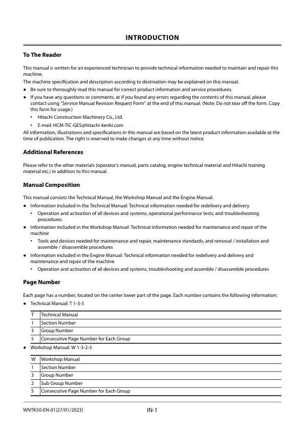
– To The Reader
– Additional References
– Manual Composition
– Page Number
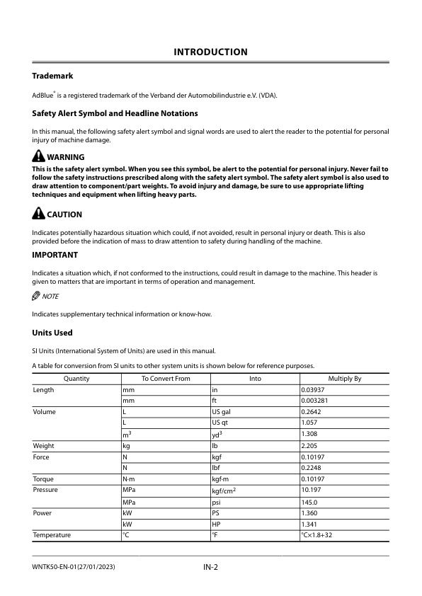
– Trademark
– Safety Alert Symbol and Headline Notations
– Units Used
SYMBOL AND ABBREVIATION
– Symbol and Abbreviation
CONTRASTING LIST OF PART NAME
– Contrasting List of Part Name between Technical Manual and Parts Catalog
SAFETY
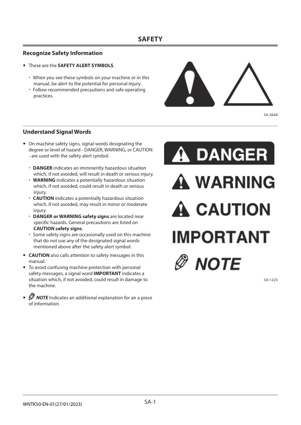
– Recognize Safety Information
– Understand Signal Words
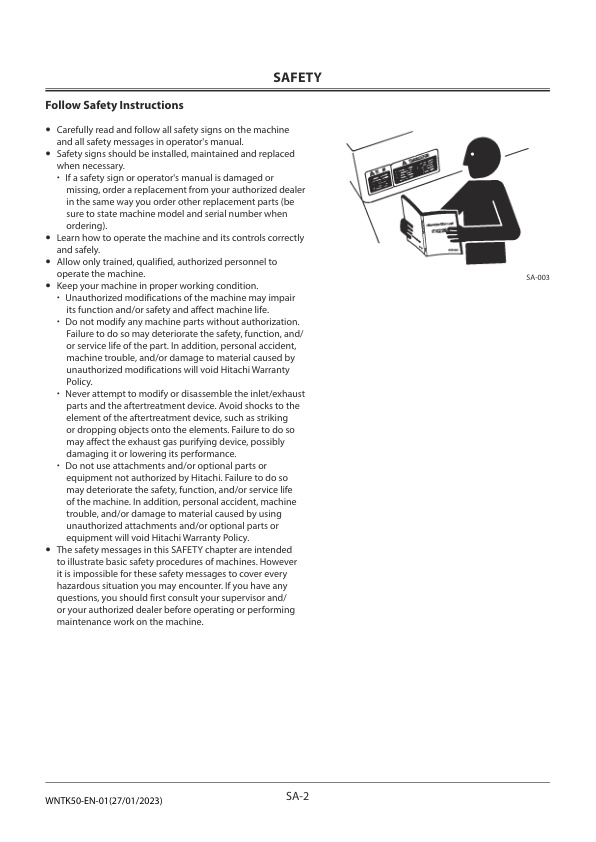
– Follow Safety Instructions
– Prepare for Emergencies
– Wear Protective Clothing
– Protect Against Noise
– Inspect Machine
– General Precautions for the Cab
– Use Handrails and Steps
– Never Ride Attachment
– Adjust Operator’s Seat
– Ensure Safety Before Rising from or Leaving Operator’s Seat
– Fasten Your Seat Belt
– Move and Operate Machine Safely
– Handle Starting Aids Safely
– Operate Only from Operator’s Seat
– Jump Starting
– Investigate Job Site Beforehand
– Equipment of Head Guard, ROPS, FOPS
– Provide Signals for Jobs Involving Multiple Machines
– Keep Riders Off Machine
– Drive Safely
– Drive Machine Safely (Work Site)
– Drive Safely with Bucket Loaded
– Drive on Snow Safely
– Travel on Public Roads Safely
– Avoid Injury from Roll Away Accidents
– Avoid Accidents from Backing Up and Turning
– Avoid Positioning Bucket or Attachment Over Anyone
– Avoid Tipping
– Never Undercut a High Bank
– Dig with Caution
– Perform Truck Loading Safely
– Avoid Power Lines
– Precautions for Operation
– Precautions for Lightning
– Protect Against Flying Debris and Falling Object
– Object Handling
– Protect Against Flying Debris
– Park Machine Safely
– Store Attachments Safely
– Transport Safely
– Handle Fluids Safely-Avoid Fires
– Practice Safe Maintenance
– Warn Others of Service Work
– Support Machine Properly
– Stay Clear of Moving Parts
– Support Maintenance Properly
– Prevent Parts from Flying
– Prevent Burns
– Replace Rubber Hoses Periodically
– Avoid High-Pressure Fluids
– Prevent Fires
– Evacuating in Case of Fire
– Beware of Exhaust Fumes
– Precautions for Welding and Grinding
– Avoid Heating Near Pressurized Fluid Lines
– Avoid Applying Heat to Lines Containing Flammable Fluids
– Precautions for Handling Accumulator and Gas Damper
– Precautions for Diesel Exhaust Fluid (DEF)
– Remove Paint Before Welding or Heating
– Beware of Asbestos and Silica Dust and Other Contamination
– Prevent Battery Explosions
– Service Air Conditioning System Safely
– Handle Chemical Products Safely
– Dispose of Waste Properly
– Notes on Aftertreatment Device
– Precautions for Communication Terminal
– Precaution for Communication Terminal Equipment
– Precautions for Aerial Angle (If Equipped)
– Precautions for Rear Obstacle Detection System (If Equipped)
– Before Returning the Machine to the Customer
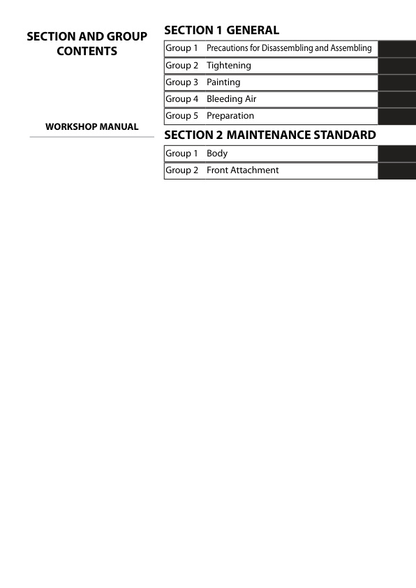
SECTION AND GROUP CONTENTS
CONTENTS
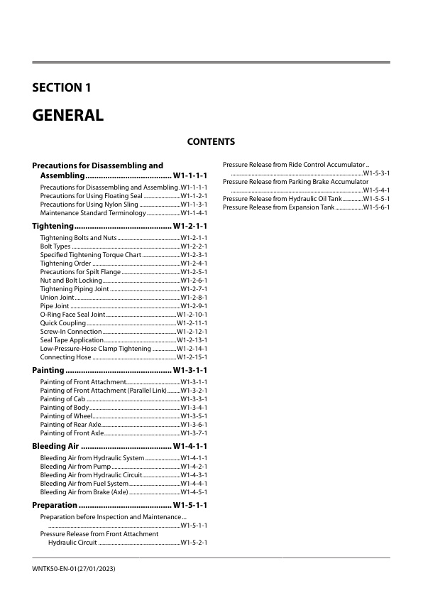
GENERAL
– Precautions for Disassembling and Assembling
— Precautions for Disassembling and Assembling
— Precautions for Using Floating Seal
— Precautions for Using Nylon Sling
— Maintenance Standard Terminology
– Tightening
— Tightening Bolts and Nuts
— Bolt Types
— Specified Tightening Torque Chart
— Tightening Order
— Precautions for Spilt Flange
— Nut and Bolt Locking
— Tightening Piping Joint
— Union Joint
— Pipe Joint
— O-Ring Face Seal Joint
— Quick Coupling
— Screw-In Connection
— Seal Tape Application
— Low-Pressure-Hose Clamp Tightening
— Connecting Hose
– Painting
— Painting of Front Attachment
— Painting of Front Attachment (Parallel Link)
— Painting of Cab
— Painting of Body
— Painting of Wheel
— Painting of Rear Axle
— Painting of Front Axle
– Bleeding Air
— Bleeding Air from Hydraulic System
— Bleeding Air from Pump
— Bleeding Air from Hydraulic Circuit
— Bleeding Air from Fuel System
— Bleeding Air from Brake (Axle)
– Preparation
— Preparation before Inspection and Maintenance
— Pressure Release from Front Attachment Hydraulic Circuit
— Pressure Release from Ride Control Accumulator
— Pressure Release from Parking Brake Accumulator
— Pressure Release from Hydraulic Oil Tank
— Pressure Release from Expansion Tank
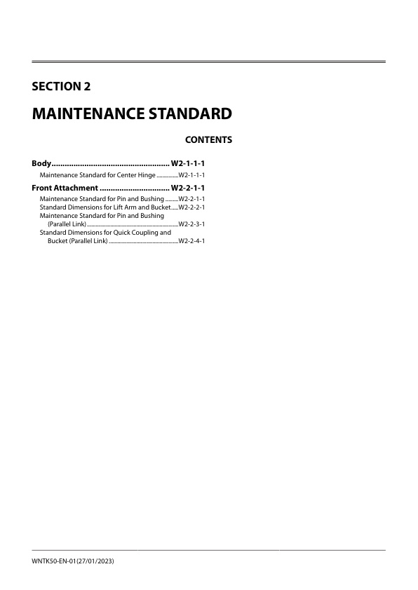
MAINTENANCE STANDARD
– Body
— Maintenance Standard for Center Hinge
– Front Attachment
— Maintenance Standard for Pin and Bushing
— Standard Dimensions for Lift Arm and Bucket
— Maintenance Standard for Pin and Bushing (Parallel Link)
— Standard Dimensions for Quick Coupling and Bucket (Parallel Link)
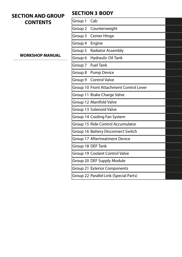
BODY
– Cab
— Removal of Parts Related to Cab
— Removal of Cab Body
— Installation of Cab Body
— Installation of Parts Related to Cab
– Counterweight
— Removal of Counterweight
— Installation of Counterweight
— Removal of Counterweight (Parallel Link)
— Installation of Counterweight (Parallel Link)
– Center Hinge
— Removal of Related Parts of Center Hinge
— Removal of Center Hinge
— Installation of Center Hinge
— Installation of Related Parts of Center Hinge
– Engine
— Preparation before Removal of Engine
— Removal of Covers and Related Parts Around the Engine
— Removal of Wire Harnesses and Hoses Around the Engine
— Removal of Engine
— Installation of Engine
— Installation of Wire Harnesses and Hoses Around the Engine
— Installation of Engine Related Parts
— Work after Installation of Engine and Installation of Covers
– Radiator Assembly
— Removal of Radiator Assembly
— Installation of Radiator Assembly
– Hydraulic Oil Tank
— Removal of Hydraulic Oil Tank (With Emergency Steering)
— Installation of Hydraulic Oil Tank (With Emergency Steering)
– Fuel Tank
— Removal of Fuel Tank
— Installation of Fuel Tank
– Pump Device
— Removal of Pump Device
— Installation of Pump Device
— Removal of Pump Device (Parallel Link)
— Installation of Pump Device (Parallel Link)
— Disassembly of Pump Device
— Assembly of Pump Device
— Disassembly of Main Pump
— Assembly of Main Pump
— Disassembly of Regulator
— Assembly of Regulator
— Removal of Priority Valve
— Installation of Priority Valve
— Structure of Priority Valve
– Control Valve
— Removal of Control Valve
— Installation of Control Valve
— Removal of Control Valve (Parallel Link)
— Installation of Control Valve (Parallel Link)
— Disassembly of Control Valve
— Assembly of Control Valve
— Disassembly of Control Valve (Parallel Link)
— Assembly of Control Valve (Parallel Link)
— Disassembly of Solenoid Valve Unit
— Assembly of Solenoid Valve Unit
– Front Attachment Control Lever
— Removal of Front Attachment Control Lever (Fingertip Control Lever Type)
— Installation of Front Attachment Control Lever (Fingertip Control Lever Type)
— Removal of Front Attachment Control Lever (Multi-Function Joystick Lever Type)
— Installation of Front Attachment Control Lever (Multi-Function Joystick Lever Type)
– Brake Charge Valve
— Removal of Brake Charge Valve
— Installation of Brake Charge Valve
— Structure of Brake Charge Valve
— Removal of Service Brake Accumulator
— Installation of Service Brake Accumulator
– Manifold Valve
— Removal of Manifold Valve
— Installation of Manifold Valve
— Disassembly of Manifold Valve
— Assembly of Manifold Valve
– Solenoid Valve
— Removal of Parking Brake Solenoid Valve Unit
— Installation of Parking Brake Solenoid Valve Unit
— Structure of Parking Brake Solenoid Valve Unit
— Removal of Quick Coupler Selector Solenoid Valve
— Installation of Quick Coupler Selector Solenoid Valve
— Structure of Quick Coupler Selector Solenoid Valve
— Removal of Quick Coupler Solenoid Valve
— Installation of Quick Coupler Solenoid Valve
– Cooling Fan System
— Removal of Fan Valve
— Installation of Fan Valve
— Structure of Fan Valve
— Removal of Fan Motor
— Installation of Fan Motor
— Structure of Fan Motor
— Removal of Fan Pump
— Installation of Fan Pump
— Disassembly of Fan Pump
— Assembly of Fan Pump
– Ride Control Accumulator
— Removal of Ride Control Accumulator
— Installation of Ride Control Accumulator
— Removal of Ride Control Accumulator (Parallel Link)
— Installation of Ride Control Accumulator (Parallel Link)
– Battery Disconnect Switch
— Removal of Battery Disconnect Switch
— Installation of Battery Disconnect Switch
– Aftertreatment Device
— Removal of Aftertreatment Device
— Installation of Aftertreatment Device
– DEF Tank
— Removal of DEF Tank
— Installation of DEF Tank
– Coolant Control Valve
— Removal of Coolant Control Valve
— Installation of Coolant Control Valve
– DEF Supply Module
— Removal of DEF Supply Module
— Installation of DEF Supply Module
– Exterior Components
— Composition of Exterior Components
— Composition of Front Cover (101)
— Composition of Front Fender (102)
— Composition of Deck (103), Step (Front) (104) and Rear Fender (Front) (105)
— Composition of Rear Fender (Rear) (106)
— Removal of Engine Cover (107)
— Installation of Engine Cover (107)
— Removal of Rear Cover (108)
— Installation of Rear Cover (108)
— Composition of Cab Under Cover (109)
— Composition of Mud Guard (Front) (110)
— Composition of Mud Guard (Rear) (112)
— Composition of Inspection Cover (111) and, Step (Rear) (114)
— Composition of Lower Cover (113)
— Removal of Side Cover (Front) (116) (with Rear Fender (Rear))
— Installation of Side Cover (Front) (116) (with Rear Fender (Rear))
— Removal of Rear Grill (117)
— Installation of Rear Grill (117)
— Removal of Left Side Cover (Rear) (118)
— Installation of Left Side Cover (Rear) (118)
— Removal of Right Side Cover (Rear) (119)
— Installation of Right Side Cover (Rear) (119)
— Composition of Under Guard (Rear) (121)
— Composition of Tool Box (120)
— Composition of DEF Tank Box (115)
— Removal of Battery Box (122)
— Installation of Battery Box (122)
— Composition of Under Guard (Front) (123)
– Parallel Link (Special Parts)
— Removal of Bucket Regenerative Valve
— Installation of Bucket Regenerative Valve
— Structure of Bucket Regenerative Valve
— Removal of Bucket Regenerative Selector Valve
— Installation of Bucket Regenerative Selector Valve
— Structure of Bucket Regenerative Selector Valve
— Removal of Reducing Valve
— Installation of Reducing Valve
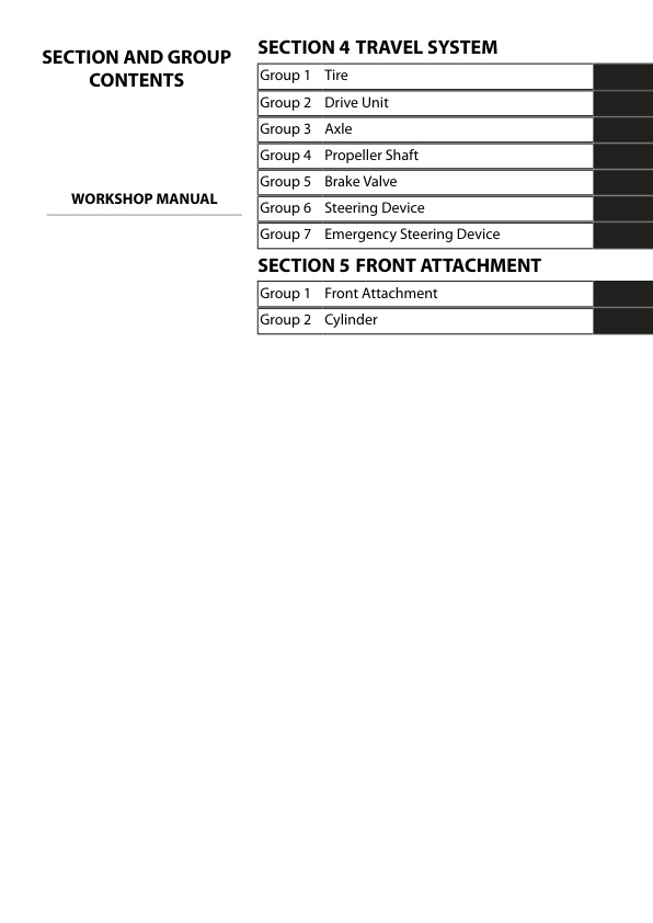
TRAVEL SYSTEM
– Tire
— Removal of Front Tire
— Installation of Front Tire
— Removal of Rear Tire
— Installation of Rear Tire
– Drive Unit
— Removal of Drive Unit
— Installation of Drive Unit
— Disassembly and Assembly of Drive Unit
— Removal of Oil Filter
— Installation of Oil Filter
— Disassembly of Torque Converter
— Assembly of Torque Converter
— Removal of Parking Brake (Replacement of Brake Friction Pad)
— Installation of Parking Brake (Replacement of Brake Friction Pad)
— Adjustment of Parking Brake
— Manual Release of Parking Brake
— Removal of Flange at Output Shaft Side
— Installation of Flange at Output Shaft Side
— Removal and Installation of Transmission Control Valve
— Removal of Duct Plate
— Installation of Duct Plate
— Disassembly of Transmission Control Valve
— Assembly of Transmission Control Valve
— Disassembly of Hydraulic Pump Drive
— Assembly of Hydraulic Pump Drive
— Removal of Clutch
— Installation of Clutch
— Disassembly of First Speed Clutch, Second Speed Clutch, and Third Speed Clutch
— Assembly of First Speed Clutch, Second Speed Clutch, and Third Speed Clutch
— Disassembly of Low-Speed Forward Clutch (KV) and Reverse Clutch (KR)
— Assembly of Low-Speed Forward Clutch (KV) and Reverse Clutch (KR)
— Disassembly of High-Speed Forward Clutch (K4)
— Assembly of High-Speed Forward Clutch (K4)
– Axle
— Removal of Front Axle
— Installation of Front Axle
— Removal of Rear Axle
— Installation of Rear Axle
— Disassembly of Axle
— Assembly of Axle
– Propeller Shaft
— Removal of Propeller Shaft
— Installation of Propeller Shaft
– Brake Valve
— Removal of Brake Valve
— Installation of Brake Valve
— Disassembly of Brake Valve
— Assembly of Brake Valve
– Steering Device
— Removal of Steering Valve
— Installation of Steering Valve
— Disassembly of Steering Valve
— Assembly of Steering Valve
— Removal of Steering Cylinder
— Installation of Steering Cylinder
— Disassembly of Steering Cylinder
— Assembly of Steering Cylinder
— Removal of Emergency Steering Check Block
— Installation of Emergency Steering Check Block
— Disassembly of Emergency Steering Valve
— Assembly of Emergency Steering Valve
– Emergency Steering Device
— Removal of Emergency Steering Pump
— Installation of Emergency Steering Pump
FRONT ATTACHMENT
– Front Attachment
— Removal of Front Attachment
— Installation of Front Attachment
— Removal of Bell Crank
— Installation of Bell Crank
— Removal of Bucket
— Installation of Bucket
— Removal of Bushing
— Installation of Bushing
— Removal of Front Attachment (Parallel Link)
— Installation of Front Attachment (Parallel Link)
— Removal of Quick Coupler (Parallel Link)
— Installation of Quick Coupler (Parallel Link)
— Position to Install (Front Attachment) (Parallel Link)
— Position to Install (Quick Coupler) (Parallel Link)
— Position to Install (Lift Arm Cylinder) (Parallel Link)
— Position to Install (Bucket Cylinder) (Parallel Link)
– Cylinder
— Removal of Lift Arm Cylinder
— Installation of Lift Arm Cylinder
— Removal of Lift Arm Cylinder (Parallel Link)
— Installation of Lift Arm Cylinder (Parallel Link)
— Disassembly of Lift Arm Cylinder
— Assembly of Lift Arm Cylinder
— Removal of Bucket Cylinder
— Installation of Bucket Cylinder
— Removal of Bucket Cylinder (Parallel Link)
— Installation of Bucket Cylinder (Parallel Link)
— Disassembly of Bucket Cylinder
— Assembly of Bucket Cylinder
— Disassembly of Bucket Cylinder (Parallel Link)
— Assembly of Bucket Cylinder (Parallel Link)
— Removal of Quick Coupler Cylinder (Parallel Link)
— Installation of Quick Coupler Cylinder (Parallel Link)
— Disassembly of Quick Coupler Cylinder (Parallel Link)
— Assembly of Quick Coupler Cylinder (Parallel Link)
SERVICE MANUAL REVISION REQUEST FORM



Reviews
There are no reviews yet.