Technical Manual Hitachi ZW180-7, ZW180PL-7 Wheel Loader TTNTK50-EN-02 (31.01.2024) (Preview)
INTRODUCTION
– To The Reader
– Additional References
– Manual Composition
– Page Number
– Trademark
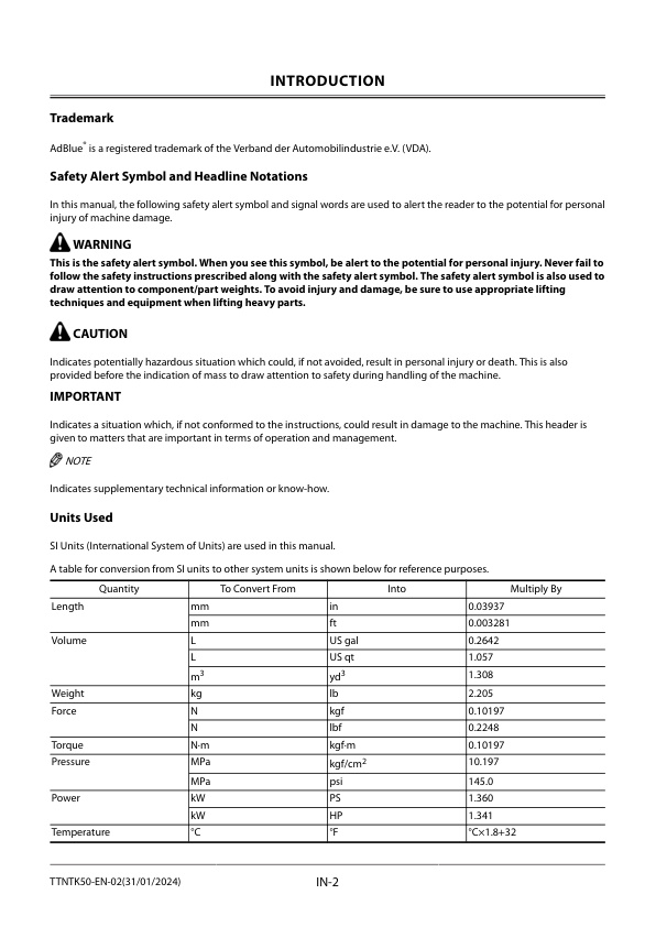
– Safety Alert Symbol and Headline Notations
– Units Used
SYMBOL AND ABBREVIATION
– Symbol and Abbreviation
CONTRASTING LIST OF PART NAME
– Contrasting List of Part Name between Technical Manual and Parts Catalog
SAFETY
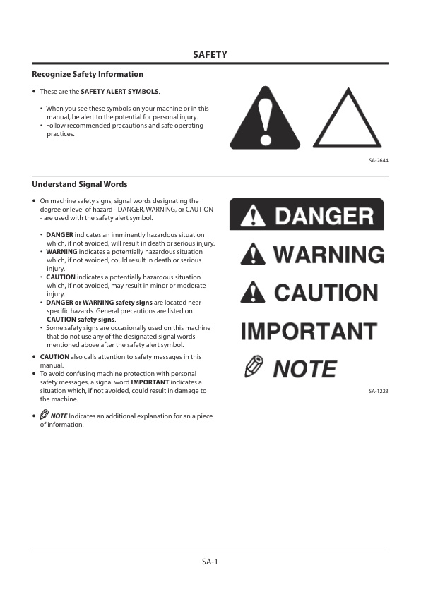
– Recognize Safety Information
– Understand Signal Words
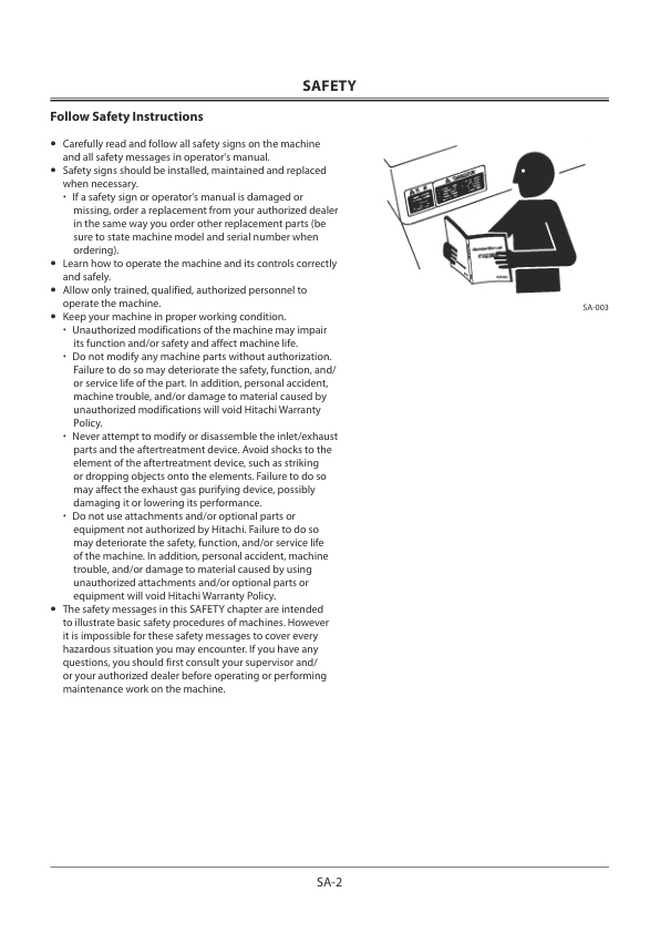
– Follow Safety Instructions
– Prepare for Emergencies
– Wear Protective Clothing
– Protect Against Noise
– Inspect Machine
– General Precautions for the Cab
– Use Handrail and Steps
– Never Ride Attachment
– Adjust Operator’s Seat
– Ensure Safety Before Rising from or Leaving
Operator’s Seat
– Fasten Your Seat Belt
– Move and Operate Machine Safely
– Handle Starting Aids Safely
– Operate Only from Operator’s Seat
– Jump Starting
– Investigate Job Site Beforehand
– Equipment of Head Guard, ROPS, FOPS
– Provide Signals for Jobs Involving Multiple Machines
– Keep Riders off Machine
– Drive Safely
– Drive Machine Safely (Work Site)
– Drive Safely with Bucket Loaded
– Drive on Snow Safely
– Travel on Public Roads Safely
– Avoid Injury from Roll Away Accidents
– Avoid Accidents from Backing Up and Turning
– Avoid Positioning Bucket or Attachment Over Anyone
– Avoid Tipping
– Never Undercut a High Bank
– Dig with Caution
– Perform Truck Loading Safely
– Avoid Power Lines
– Precautions for Operation
– Precautions for Lightning
– Protect Against Flying Debris and Falling Object
– Object Handling
– Protect Against Flying Debris
– Park Machine Safely
– Store Attachments Safely
– Transport Safely
– Handle Fluids Safely−Avoid Fires
– Practice Safe Maintenance
– Warn Others of Service Work
– Support Machine Properly
– Stay Clear of Moving Parts
– Support Maintenance Properly
– Prevent Parts from Flying
– Prevent Burns
– Replace Rubber Hoses Periodically
– Avoid High-Pressure Fluids
– Prevent Fires
— Check for Oil Leaks:
— Check for Short:
— Clean up Flammable Materials:
— Clean up Flammable Materials:
— Evacuating in Case of Fire
– Beware of Exhaust Fumes
– Precautions for Welding and Grinding
– Avoid Heating Near Pressurized Fluid Lines
– Avoid Applying Heat to Lines Containing Flammable Fluids
– Precautions for Handling Accumulator and Gas Damper
– Precautions for Diesel Exhaust Fluid (DEF)
– Remove Paint Before Welding or Heating
– Beware of Asbestos and Silica Dust and Other Contamination
– Prevent Battery Explosions
– Service Air Conditioning System Safely
– Handle Chemical Products Safely
– Dispose of Waste Properly
– Notes on Aftertreatment Device
– Precautions for Communication Terminal
– Precautions for Communication Terminal Equipment
– Precautions for Aerial Angle (If Equipped)
– Precautions for Rear Obstacle Detection System (If Equipped)
– Before Returning the Machine to the Customer
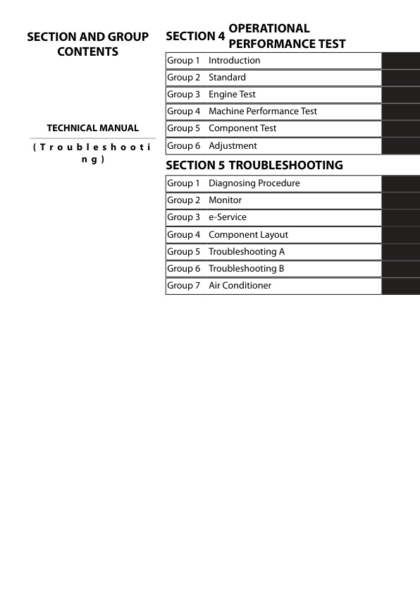
SECTION AND GROUP CONTENTS
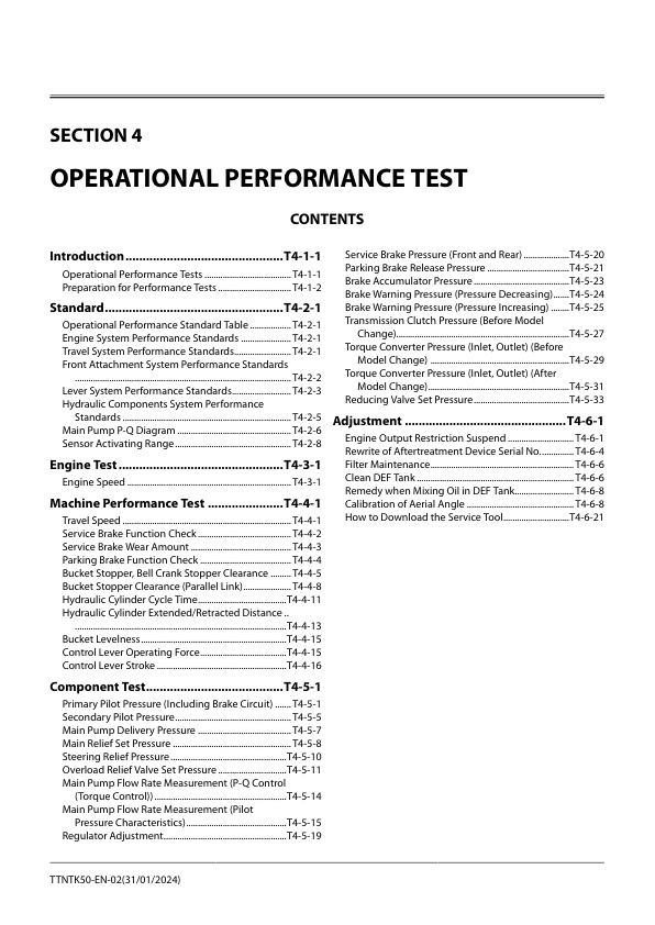
CONTENTS
OPERATIONAL PERFORMANCE TEST
– Introduction
— Operational Performance Tests
— Preparation for Performance Tests
– Standard
— Operational Performance Standard Table
— Engine System Performance Standards
— Travel System Performance Standards
— Front Attachment System Performance Standards
— Lever System Performance Standards
— Hydraulic Components System Performance Standards
— Main Pump P-Q Diagram
— Sensor Activating Range
– Engine Test
— Engine Speed
– Machine Performance Test
— Travel Speed
— Service Brake Function Check
— Service Brake Wear Amount
— Parking Brake Function Check
— Bucket Stopper, Bell Crank Stopper Clearance
— Bucket Stopper Clearance (Parallel Link)
— Hydraulic Cylinder Cycle Time
— Hydraulic Cylinder Extended/Retracted Distance
— Bucket Levelness
— Control Lever Operating Force
— Control Lever Stroke
– Component Test
— Primary Pilot Pressure (Including Brake Circuit)
— Secondary Pilot Pressure
— Main Pump Delivery Pressure
— Main Relief Set Pressure
— Steering Relief Pressure
— Overload Relief Valve Set Pressure
— Main Pump Flow Rate Measurement (P-Q Control (Torque Control))
— Main Pump Flow Rate Measurement (Pilot Pressure Characteristics)
— Regulator Adjustment
— Service Brake Pressure (Front and Rear)
— Parking Brake Release Pressure
— Brake Accumulator Pressure
— Brake Warning Pressure (Pressure Decreasing)
— Brake Warning Pressure (Pressure Increasing)
— Transmission Clutch Pressure (Before Model Change)
— Transmission Clutch Pressure (After Model Change)
— Torque Converter Pressure (Inlet, Outlet) (Before Model Change)
— Torque Converter Pressure (Inlet, Outlet) (After Model Change)
— Reducing Valve Set Pressure
– Adjustment
— Engine Output Restriction Suspend
— Rewrite of Aftertreatment Device Serial No.
— Filter Maintenance
— Clean DEF Tank
— Remedy when Mixing Oil in DEF Tank
— Calibration of Aerial Angle
— How to Download the Service Tool
TROUBLESHOOTING
– Diagnosing Procedure
— Introduction
— Diagnosis Procedure
— Electrical System Inspection
— Precautions for Inspection and Maintenance
— Instructions for Disconnecting Connectors
— Instructions for Removing Relays
— Fuse Inspection
— Fuse Connection Destination
— Fusible Link Inspection
— Battery Voltage Check
— Alternator Check
— Continuity Check
— Voltage and Current Measurement of 24-Volt Circuit
— Voltage and Current Measurement of 5-Volt Circuit
— Check by False Signal
— Test Wire Harness
— Removal of MC (Main Controller)
— Installation of MC (Main Controller)
— Removal of TCU
— Installation of TCU
— Removal of PLCU
— Installation of PLCU
— Removal of Aerial Angle Controller
— Installation of Aerial Angle Controller
— Removal of Monitor Controller
— Installation of Monitor Controller
– Monitor
— Basic Screen of Monitor
— Operating Procedures of Service Menu
— How to Display Service Menu
— How to Display Troubleshooting Screen
— How To Display Monitoring
— Monitoring Items of Engine Controller (ECM)
— Main Controller (MC) Monitoring Items
— TCU Monitoring Items
— Monitoring Items of Column Monitor Controller
— PLCU Monitoring Items
— Monitoring Items of Information Controller
— Monitoring Items of Air Conditioner Unit
— How To Display Controller Version
— How To Display Communication Terminal Status
— List of Communication Terminal Status
— How to Display Machine Setting
— List of Machine Setting Items
— Transmission Learning
— Lift Arm Angle Sensor Learning
— Bell Crank Angle Sensor Learning
— Lift Arm Cylinder Length (Maximum Extension) Learning
— Bucket Cylinder Length (Maximum Extension) Learning
— Bucket Cylinder Length (Maximum Contraction) Learning
— Bucket Dump Stopper Contact Cylinder Length Learning
— Bucket Tilt Stopper Contact Cylinder Length Learning
— Brake Pedal Angle Sensor Learning
— Bucket Grounding Position Adjustment
— Payload Checker Non-Load Learning
— How To Display Monitor Setting
— List of Monitor Setting Items
— How To Display Aftertreatment Device No.
— Engine Tachometer
— DEF Gauge
— Coolant Temperature Gauge
– e-Service
— Outline of e-Service
— List of Operation Data
— Communication System
– Component Layout
— Main Component (Overview)
— Main Component (Overview) (Parallel Link Front)
— Main Component
— Main Component (Parallel Link Front)
— Electrical System (Overview)
— Air Cleaner and Radiator Assembly
— Radiator Assembly
— Battery Box
— Hydraulic Oil Tank
— Fuel Tank
— Drive Unit
— Front Axle
— Cab
— Front Console
— Panel Switch
— Right Console
— Rear Console
— Control Unit
— Column Monitor
— Engine
— Aftertreatment Device
— Fan Valve
— Pump Device
— Control Valve
— Manifold Valve
— Parking Brake Solenoid Valve Unit
— Brake Charge Valve
— Steering Priority Valve
— Emergency Steering Valve
— Emergency Steering Pump Unit
— DEF Tank
— DEF Supply Module
— Brake Valve
– Troubleshooting A
— Troubleshooting A (Base Machine Diagnosis by Using Fault Codes) Procedure
— Contents of Troubleshooting A
— HCM Fault Code List
— Front Attachment Device Fault Code List
— TCU Fault Code List
— ECM Fault Code List
– Troubleshooting B
— Troubleshooting B (Machine Diagnosis by Using Trouble Symptom) Procedure
— Contents of Troubleshooting B
— Relationship between Machine Trouble Symptoms and Related Parts
— When a Fault Occurs in MC (Main Controller)
— When a Fault Occurs in PLCU
— When a Fault Occurs in Accelerator Pedal Sensor
— When a Fault Occurs in Travel Mode Switch
— When a Fault Occurs in Power Mode Switch
— When a Fault Occurs in Quick Power Switch
— When a Fault Occurs in Clutch Cut Position Switch
— When a Fault Occurs in Fan Reverse Rotation Switch
— When a Fault Occurs in Forward/Reverse Lever
— When a Fault Occurs in Forward/Reverse Selector Switch
— When a Fault Occurs in Forward/Reverse Switch
— When a Fault Occurs in Shift Switch
— When a Fault Occurs in Downshift Switch
— When a Fault Occurs in Hold Switch
— When a Fault Occurs in Manual Regeneration Switch
— When a Fault Occurs in Ride Control Switch
— When a Fault Occurs in Parking Switch
— When a Fault Occurs in Control Lever Lock Switch
— When a Fault Occurs in Control Lever Lock Solenoid Valve
— When a Fault Occurs in Hydraulic Oil Temperature Sensor
— When a Fault Occurs in Torque Converter Oil Temperature Sensor
— When a Fault Occurs in DOC Inlet Exhaust Temperature Sensor
— When a Fault Occurs in DOC Outlet Exhaust Temperature Sensor
— When a Fault Occurs in SCR Inlet Exhaust Temperature Sensor
— When a Fault Occurs in SCR Outlet Exhaust Temperature Sensor
— When a Fault Occurs in Pump Delivery Pressure Sensor
— When a Fault Occurs in Fan Circuit Pressure Sensor
— When a Fault Occurs in Steering Pressure Switch
— When a Fault Occurs in Emergency Steering Pump Delivery Pressure Sensor
— When a Fault Occurs in Parking Brake Pressure Sensor
— When a Fault Occurs in Service Brake Primary Pressure Sensor
— When a Fault Occurs in Service Brake Secondary Pressure Sensor
— When a Fault Occurs in Primary Pilot Pressure Sensor
— When a Fault Occurs in Lift Arm Angle Sensor
— When a Fault Occurs in Bucket Angle Sensor
— When a Fault Occurs in Torque Converter Input Shaft Speed Sensor
— When a Fault Occurs in Torque Converter Output Shaft Speed Sensor
— When a Fault Occurs in Transmission Intermediate Shaft Speed Sensor
— When a Fault Occurs in Vehicle Speed Sensor
— When a Fault Occurs in Refrigerant Pressure Sensor
— When a Fault Occurs in Ride Control Solenoid Valve
— When a Fault Occurs in Parking Brake Solenoid Valve
— When a Fault Occurs in Torque Control Solenoid Valve
— When a Fault Occurs in Fan Speed Control Solenoid Valve
— When a Fault Occurs in Fan Reverse Rotation Control Solenoid Valve
— When a Fault Occurs in Forward/Reverse Clutch Solenoid Valves
— When a Fault Occurs in Speed Shift Solenoid Valve
— When a Fault Occurs in Main Relief Valve
— When a Fault Occurs in Overload Relief Valve
— When a Fault Occurs in Lift Arm Anti-Drift Valve
— When a Fault Occurs in Pump Flow Rate Control Valve
— When a Fault Occurs in Ride Control Spool
— When a Fault Occurs in Fan Reverse Rotation Spool (Fan Valve)
— When a Fault Occurs in Steering Main Relief Valve
— When a Fault Occurs in Bucket Regenerative Valve (Parallel Link)
— When a Fault Occurs in Bucket Regenerative Selector Valve (Parallel Link)
— Identification Symbols for Troubleshooting B
— Correlation between Trouble Symptoms and Part Failures
— Parts Related with E-1 Starter does not rotate.
— Parts Related with E-2 Even if starter rotates, engine does not start.
— Parts Related with E-3 Even if power mode switch is operated, power mode is not shifted.
— Parts Related with E-4 Engine starts with forward/reverse lever set in the forward position or reverse position.
— Parts Related with E-5 Even if key switch is turned OFF, engine does not stop.
— Parts Related with E-9 Auto shut-down is not activated.
— Parts Related with A-1 Only actuators of the front attachment do not work.
— Parts Related with A-2 Actuator speed of front attachment and steering are slow.
— Parts Related with A-3 Actuator of front attachment does not stop even if a control lever is set to neutral.
— Parts Related with A-4 Fan speed does not change.
— Parts Related with A-5 Fan does not rotate in reverse when fan reverse rotation switch is set in the ON or AUTO position.
— Parts Related with F-1 All front attachment actuator powers are weak.
— Parts Related with F-2 Front attachment drifts remarkably.
— Parts Related with F-3 Some cylinders are not operated or speed are slow.
— Parts Related with F-4 Shock is large when stopping lift arm raise/lower operation or dumping bucket.
— Parts Related with F-5 Bucket auto leveler control is not activated. (Detent is not held.)
— Parts Related with F-6 Lift arm float control is not activated. (Detent is not held.)
— Parts Related with F-7 The lift arm auto leveler height kickout control is not activated.
— Parts Related with F-8 The lift arm auto leveler lower kickout control is not activated.
— Parts Related with F-9 The ride control is not activated.
— Parts Related with F-10 Bucket tilt speed is slow. (Parallel link)
— Parts Related with F-11 Bucket dump speed is slow. (Parallel link)
— Parts Related with T-1 Machine does not travel.
— Parts Related with T-2 Although forward/reverse lever is set to neutral position, machine travels.
— Parts Related with T-3 Clutch cutoff control is inoperable.
— Parts Related with T-4 Travel mode can not be selected.
— Parts Related with T-5 Although shift switch is operated, transmission does not shift.
— Parts Related with T-6 Although machine speed changes, transmission will not shift change automatically.
— Parts Related with T-7 Transmission does not downshift when pushing downshift switch.
— Parts Related with T-8 Selected gear is not held when pushing hold switch.
— Parts Related with B-1 Parking brake control does not operate with the engine running.
— Parts Related with B-2 Parking brake is not released with the engine running.
— Parts Related with B-3 Service brake braking force is weak.
— Parts Related with ST-1 Steering operation power is weak.
— Parts Related with ST-2 Steering operation speed is slow.
— Parts Related with ST-3 Shock of steering operation is large.
— Parts Related with ST-4 Emergency steering is not operated. (Automatic operation check when the engine starts)
— Parts Related with O-1 Work light are not ON.
— Parts Related with O-2 Cab light is not ON.
— Parts Related with O-3 Wiper is not operated.
— Parts Related with O-4 Washer is not operated.
— Parts Related with O-5 Clearance lights, tail lights, and license plate light are not ON.
— Parts Related with O-6 Headlights are not ON.
— Parts Related with O-7 Headlights are not shifted to high beam.
— Parts Related with O-8 Hazard lights are not operated.
— Parts Related with O-9 Turn signal lights are not operated.
— Parts Related with O-10 Horn does not sound.
— Parts Related with O-11 Reverse buzzer does not sound.
— Parts Related with O-12 Brake lights are not ON.
— E-1 Starter does not rotate.
— E-2 Even if starter rotates, engine does not start.
— E-3 Even if power mode switch is operated, power mode is not shifted.
— E-4 Engine Starts with forward/reverse lever set in the forward position or reverse position.
— E-5 Even if key switch is turned OFF, engine does not stop.
— E-9 Auto shut-down is not activated.
— A-1 Only actuators of the front attachment do not work.
— A-2 Actuator speed of front attachment and steering are slow.
— A-3 Actuator of front attachment does not stop even if a control lever is set to neutral.
— A-4 Fan speed does not change.
— A-5 Fan does not rotate in reverse when fan reverse rotation switch is set in the ON or AUTO position.
— F-1 All front attachment actuator powers are weak.
— F-2 Front attachment drifts remarkably.
— F-3 Some cylinders are not operated or speed are slow.
— F-4 Shock is large when stopping lift arm raise/lower operation or dumping bucket.
— F-5 Bucket auto leveler control is not activated. (Detent is not held.)
— F-6 Lift arm float control is not activated. (Detent is not held.)
— F-7 The lift arm auto leveler height kickout control is not activated.
— F-8 Lift arm auto leveler lower kickout control is not activated.
— F-9 The ride control is not activated.
— F-10 Bucket tilt speed is slow. (Parallel link)
— F-11 Bucket dump speed is slow. (Parallel link)
— T-1 Machine does not travel.
— T-2 Although forward/reverse lever is set to neutral position, machine travels.
— T-3 Clutch cutoff control is inoperable.
— T-4 Travel mode can not be selected.
— T-5 Although shift switch is operated, transmission does not shift.
— T-6 Although vehicle speed changes, transmission will not shift change automatically.
— T-7 Transmission does not downshift when pushing downshift switch
— T-8 Selected gear is not held when pushing hold switch.
— B-1 Parking brake control does not operate with the engine running.
— B-2 Parking brake is not released with the engine running.
— B-3 Service brake braking force is weak.
— ST-1 Steering operation power is weak.
— ST-2 Steering operation speed is slow.
— ST-3 Shock of steering operation is large.
— ST-4 Emergency steering is not operated. (Automatic operation check when the engine starts)
— O-1 Work light are not ON.
— O-2 Cab light is not ON.
— O-3 Wiper is not operated.
— O-4 Washer is not operated.
— O-5 Clearance lights, tail lights, and license plate light are not ON.
— O-6 Headlights are not ON.
— O-7 Headlights are not shifted to high beam.
— O-8 Hazard lights are not operated.
— O-9 Turn signal lights are not operated.
— O-10 Horn does not sound.
— O-11 Reverse buzzer does not sound.
— O-12 Brake lights are not ON.
— Exchange Inspection Method
— Air Bleeding Procedures for Brake (Axle)
– Air Conditioner
— Outline of Air Conditioner
— Component Layout of Air Conditioner
— Functions of Main Electrical Parts
— Troubleshooting of Air Conditioner
— Monitor Controller (Monitor) Fault Code 13911-3
— Monitor Controller (Monitor) Fault Code 13912-4
— Monitor Controller (Monitor) Fault Code 13913-3
— Monitor Controller (Monitor) Fault Code 13914-4
— Monitor Controller (Monitor) Fault Code 13918-4
— Monitor Controller (Monitor) Fault Code 13921-3
— Monitor Controller (Monitor) Fault Code 13922-4
— Monitor Controller (Monitor) Fault Code 13943-2
— Monitor Controller (Monitor) Fault Code 13944-2
— Monitor Controller (Monitor) Fault Code 13951-2
— Monitor Controller (Monitor) Fault Code 13991-2
— Monitor Controller (Monitor) Fault Code 13992-2
— Faulty Cooling (1)
— Faulty Cooling (2)
— Faulty Cooling (3)
— Faulty Cooling (4)
— Faulty Cooling (5)
— Faulty Heating (1)
— Faulty Heating (2)
— Others
— Blower motor does not operate.
— Compressor clutch does not operate.
— Cooling Circuit Check by Using Manifold Gauge
— Work after Replacing Components
— Refill compressor oil
— Necessity of Purging
— Procedures for Charging Air Conditioner with Refrigerant
— Warm-Up Operation
— Hose and Pipe Tightening Torque
SERVICE MANUAL REVISION REQUEST FORM
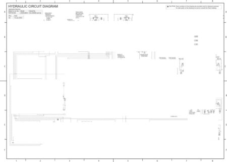
The Attached Diagram List


Reviews
There are no reviews yet.