


Hitachi ZX8-2, ZX10U-2 Excavator W1MR-E-00 (Preview)
W1MR-E-00
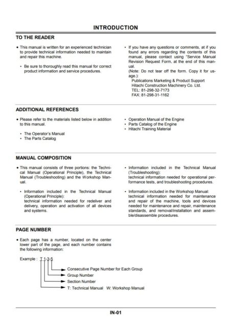
INTRODUCTION
CONTENTS
SAFETY
RECOGNIZE SAFETY INFORMATION
UNDERSTAND SIGNAL WORDS
FOLLOW SAFETY INSTRUCTIONS
PREPARE FOR EMERGENCIES
WEAR PROTECTIVE CLOTHING
PROTECT AGAINST NOISE
INSPECT MACHINE
USE HANDHOLDS AND STEPS
FASTEN YOUR SEAT BELT (ROLL BAR EQUIPPED MACHINES)
MOVE AND OPERATE MACHINE SAFELY
OPERATE ONLY FROM OPERATOR’S SEAT
JUMP STARTING
INVESTIGATE JOB SITE BEFOREHAND
PROVIDE SIGNALS FOR JOBS INVOLVING MULTIPLE NUMBERS OF MACHINES
CONFIRM DIRECTION OF MACHINE TO BE DRIVEN
DRIVE MACHINE SAFELY
AVOID INJURY FROM ROLLAWAY ACCIDENTS
AVOID INJURY FROM BACK-OVER AND SWING ACCIDENTS
KEEP PERSONNEL CLEAR FROM WORKING AREA
NEVER POSITION BUCKET OVER ANYONE
AVOID UNDERCUTTING
AVOID TIPPING
NEVER UNDERCUT A HIGH BANK
DIG WITH CAUTION
OPERATE WITH CAUTION
AVOID POWER LINES
DO NOT USE FOR CRANING OPERATIONS
P
ROTECT AGAINST FLYING DEBRIS
PARK MACHINE SAFELY
HANDLE FLUIDS SAFELY — AVOID FIRES
SAFETY TRANSPORTING
PRACTICE SAFE MAINTENANCE
WARN OTHERS OF SERVICE WORK
SUPPORT MACHINE PROPERLY
STAY CLEAR OF MOVING PARTS
PREVENT PARTS FROM FLYING
STORE ATTACHMENTS SAFELY
PREVENT BURNS
REPLACE RUBBER HOSES PERIODICALLY
AVOID HIGH-PRESSURE FLUIDS
PREVENT FIRES
EVACUATING IN CASE OF FIRE
BEWARE OF EXHAUST FUMES
PRECAUTIONS FOR WELDING AND GRINDING
AVOID HEATING NEAR PRESSURIZED FLUID LINES
AVOID APPLYING HEAT TO LINES CONTAINING FLAMMABLE FLUIDS
REMOVE PAINT BEFORE WELDING OR HEATING
PREVENT BATTERY EXPLOSIONS
PRECAUTIONS FOR HANDLING REFRIGERANT
H
ANDLE CHEMICAL PRODUCTS SAFELY
DISPOSE OF WASTE PROPERLY
SECTION 1
GENERAL
Group 1 Precautions for Disassembling and Assembling
PRECAUTIONS FOR DISASSEMBLING
AND ASSEMBLING
Group 2 Tightening
TIGHTENING TORQUE SPECIFICATIONS
TORQUE CHART
PIPING JOINT
PERIODIC REPLACEMENT OF PARTS
Group 3 Painting
PAINTING
Group 4 Bleeding Air
BLEED AIR FROM HYDRAULIC OIL TANK
SECTION 2
UPPERSTRUCTURE
Group 1 Main Frame
REMOVE AND INSTALL MAIN FRAME
Group 2 Pump Device
REMOVE AND INSTALL PUMP DEVICE
DISASSEMBLE PUMP DEVICE
ASSEMBLE PUMP DEVICE
STRUCTURE OF PILOT PUMP
Group 3 Control Valve
REMOVE AND INSTALL CONTROL VALVE
DISASSEMBLE AND ASSEMBLE CONTROL VALVE
DISASSEMBLE BODY
ASSEMBLE BODY
DISASSEMBLE SPOOL
ASSEMBLE SPOOL
DISASSEMBLE AND ASSEMBLE CHECK VALVE
Group 5 Swing Device
REMOVE AND INSTALL SWING DEVICE
DISASSEMBLE SWING DEVICE
ASSEMBLE SWING DEVICE
Group 5 Pilot Valve
REMOVE AND INSTALL PILOT VALVE (ZAXIS10U-2 ONLY)
DISASSEMBLE PILOT VALVE (ZAXIS10U-2 ONLY)
ASSEMBLE PILOT VALVE (ZAXIS10U-2
ONLY)
Group 6 Solenoid Valve
REMOVE AND INSTALL 2-SPOOL SOLENOID VALVE
DISASSEMBLE 2-SPOOL SOLENOID VALVE
ASSEMBLE 2-SPOOL SOLENOID VALVE
REMOVE AND INSTALL AIR BLEED SOLENOID VALVE
STRUCTURE OF AIR BLEED SOLENOID VALVE
SECTION 3 UNDERCARRIAGE
Group 1 Swing Bearing
REMOVE AND INSTALL SWING BEARING
Group 2 Travel Device
REMOVE AND INSTALL TRAVEL DEVICE
DISASSEMBLE TRAVEL DEVICE
ASSEMBLE TRAVEL DEVICE
DISASSEMBLE TRAVEL MOTOR
ASSEMBLE TRAVEL MOTOR
DISASSEMBLE AND ASSEMBLE BRAKE VALVE
MAINTENANCE STANDARD
Group 3 Center Joint
REMOVE AND INSTALL CENTER JOINT
DISASSEMBLE CENTER JOINT
ASSEMBLE CENTER JOINT
Group 4 Track Adjuster
REMOVE AND INSTALL TRACK ADJUSTER
DISASSEMBLE AND ASSEMBLE TRACK ADJUSTER
Group 5 Front Idler
REMOVE AND INSTALL FRONT IDLER
DISASSEMBLE AND ASSEMBLE FRONT IDLER
MAINTENANCE STANDARD
Group 6 Upper and Lower Roller
REMOVE AND INSTALL LOWER ROLLER
STRUCTURE OF LOWER ROLLER
MAINTENANCE STANDARD
Group 7 Track
REMOVE AND INSTALL TRACK
MAINTENANCE STANDARD
SECTION 4 FRONT ATTACHMENT
Group 1 Front Attachment
REMOVE AND INSTALL FRONT ATTACHMENT
MAINTENANCE STANDARD
STANDARD DIMENSIONS FOR ARM AND BUCKET CONNECTION
Group 2 Cylinder
REMOVE AND INSTALL CYLINDER
DISASSEMBLE BOOM CYLINDER
ASSEMBLE BOOM CYLINDER
DISASSEMBLE ARM CYLINDER
ASSEMBLE ARM CYLINDER
DISASSEMBLE BUCKET AND BOOM SWING CYLINDERS
ASSEMBLE BUCKET AND BOOM SWING CYLINDERS
DISASSEMBLE SIDE FRAME EXTEND/RETRACT CYLINDER
ASSEMBLE SIDE FRAME EXTEND/RETRACT CYLINDER
DISASSEMBLE BLADE CYLINDER
ASSEMBLE BLADE CYLINDER
MAINTENANCE STANDARD
SECTION 5 ENGINE
Section 1 Introduction
Introduction
Yanmar Warranties
Yanmar Limited Warranty
What is Covered by this Warranty?
How Long is the Warranty Period?
What the Engine Owner Must Do:
To Locate an Authorized Yanmar Industrial Engine Dealer or Distributor:
What Yanmar Will Do:
What is Not Covered by this Warranty?
Warranty Limitations:
Warranty Modifications:
Questions:
Retail Purchaser Registration
Emission System Warranty
Yanmar Co., Ltd. Limited Emission Control System Warranty – USA Only
Your Warranty Rights and Obligations:
California
Manufacturer’s Warranty Period:
Warranty Coverage:
Warranted Parts:
Exclusions:
Owner’s Warranty Responsibilities:
Safety
Safety Statements
Safety Precautions
General Service Information
Component Identification
Location of Labels
Engine Nameplate (Typical)
EPA / ARB Emission Control Regulations – USA Only
Emission Control Labels
EPA / ARB Labels
The 97/68/EC Directive Certified Engines
Engine Family
Function of Major Engine Components
Function of Cooling System Components
Diesel Fuel
Diesel Fuel Specifications
Additional Technical Fuel Requirements
Bio-Diesel Fuels
Filling the Fuel Tank
Priming the Fuel System
Engine Oil
Engine Oil Specifications
Service Categories
Definitions
Additional Technical Engine oil Requirements:
Engine Oil Viscosity
Checking Engine Oil
Adding Engine Oil
Engine Oil Capacity (Typical)
Engine Coolant
Engine Coolant Specifications
Additional Technical Coolant Specifications:
Alternative Engine Coolant
Filling Radiator with Engine Coolant
Engine Coolant Capacity (Typical)
Specifications
Description of Model Number
Engine Speed Specifications
Engine General Specifications
Principal Engine Specifications
2TNV70
3TNV70
3TNV76
Engine Service Information
Tightening Torques for Standard Bolts and Nuts
Abbreviations and Symbols
Abbreviations
Symbols
Unit Conversions
Unit Prefixes
Units of Length
Units of Volume
Units of Mass
Units of Force
Units of Torque
Units of Pressure
Units of Power
Units of Temperature
Periodic Maintenance
Introduction
Precautions
The Importance of Periodic Maintenance
Performing Periodic Maintenance
Yanmar Replacement Parts
Required EPA / ARB Maintenance – USA Only
EPA / ARB Installation Requirements – USA Only
Periodic Maintenance Schedule
Periodic Maintenance Procedures
After Initial 50 Hours of Operation
Replace Engine Oil and Engine Oil Filter
Check and Adjust Cooling Fan V-Belt
Every 50 Hours of Operation
Drain Fuel Filter / Water Separator
Check Battery
Every 250 Hours of Operation
Drain Fuel Tank
Replace Engine Oil and Engine Oil Filter
Check and Clean Radiator Fins
Check and Adjust Cooling Fan V-Belt
Check and Adjust the Governor Lever and Engine Speed Control
Clean Air Cleaner Element
Every 500 Hours of Operation
Replace Air Cleaner Element
Replace Fuel Filter
Clean Fuel Filter / Water Separator
Every 1000 Hours of Operation
Drain, Flush and Refill Cooling System with New Coolant
Adjust Intake / Exhaust Valve Clearance
Every 1500 Hours of Operation
Inspect, Clean and Test Fuel Injectors
Inspect Crankcase Breather System
Every 2000 Hours of Operation
Check and Replace Fuel Hoses and Engine Coolant Hoses
Lap the Intake and Exhaust Valves
Engine
Before You Begin Servicing
Introduction
Cylinder Head Specifications
Adjustment Specifications
Cylinder Head
Intake / Exhaust Valve and Guide
Push Rod
Valve Spring
Rocker Arm and Shaft
Camshaft and Timing Gear Train Specifications
Camshaft
Idler Gear Shaft and Bushing
Timing Gear Backlash
Crankshaft and Pistons Specifications
Crankshaft
Crankshaft Reconditioning
Thrust Bearing
Piston
Piston Ring
Connecting Rod
Connecting Rod Small End
Connecting Rod Big End
Connecting Rod Distortion
Tappet
Cylinder Block Specifications
Cylinder Block
Special Torque Chart
Torque for Bolts and Nuts
Special Service Tools
Measuring Instruments
Cylinder Head
Cylinder Head Components
Disassembly of Cylinder Head
Removal of Intake Manifold / Valve Cover
Removal of Glow Plugs
Removal of Rocker Arm Assembly
Disassembly of Rocker Arm Assembly
Removal of Cylinder Head
Removal of Intake / Exhaust Valves
Removal of Valve Guides
Cleaning of Cylinder Head Components
Inspection of Cylinder Head Components
Inspection of Push Rods
Inspection of Rocker Arm Assembly
Inspection of Valve Guides
Inspection of Cylinder Head
Inspection of Intake and Exhaust Valves
Inspection of Valve Springs
Reassembly of Cylinder Head
Reassembly of Valve Guides
Reassembly of Intake and Exhaust Valves
Reassembly of Cylinder Head
Reassembly of Rocker Arm Assembly
Reassembly of Intake Manifold / Valve Cover
Measuring and Adjusting Valve Clearance
3-Cylinder Engines
Cylinder Block
Crankshaft and Camshaft Components
Disassembly of Cylinder Block Components
Disassembly of Camshaft and Timing Components
Removal of Timing Gear Case Cover
Checking Timing Gear Backlash
Measuring Idler Gear-to-Crankshaft Gear Backlash
Measuring Idler Gear-to-Camshaft Gear Backlash
Removal of Timing Gears
Removal of Oil Pan
Removal of Camshaft
Removal of Gear Case
Disassembly of Crankshaft and Piston Components
Removal of Pistons
Removal of Crankshaft
Inspection of Crankshaft and Camshaft Components
Replacement of Crankshaft Oil Seals
Crankshaft Bearing Oil Clearance
Inspection of Cylinder Block
Inspection of Pistons, Piston Rings and Wrist Pin
Inspection of Connecting Rod
Inspection of Tappets
Inspection of Crankshaft
Reconditioning the Crankshaft
Inspection of Camshaft
Inspection of Camshaft Bushing and Bores
Inspection of Idler Gear and Shaft
Honing and Boring
Reassembly of Crankshaft and Piston Components
Reassembly of Pistons
Installation of Crankshaft
Installation of Pistons
Reassembly of Camshaft and Timing Components
Installation of Gear Case
Installation of Camshaft
Installation of Timing Gears
Installation of Gear Case Cover
Installation of Oil Pan
Final Assembly of Engine
Fuel System
Before You Begin Servicing
Introduction
Fuel Injection Pump
Stop Solenoid
Fuel System Specifications
Special Torque Chart
Test and Adjustment Specifications
Special Service Tools
Measuring Instruments
Fuel System Diagram
Fuel System Components
Fuel Injection Lines
Removal of High-Pressure Fuel Injection Lines
Installation of High-Pressure Fuel Injection Lines
Removal of Fuel Return Line
Installation of Fuel Return Line
Fuel Injection Pump
Removal of Fuel Injection Pump
Installation of Fuel Injection Pump
Checking and Adjusting Fuel Injection Timing
Checking Fuel Injection Timing
Adjusting Fuel Injection Timing
Fuel Injectors
Removal of Fuel Injectors
Testing of Fuel Injectors
Fuel Injector Test Results
Disassembly and Inspection of Fuel Injectors
Adjusting Fuel Injector Pressure
Reassembly of Fuel Injectors
Installation of the Fuel Injectors
Cooling System
Before You Begin Servicing
Introduction
Cooling System Diagram
Engine Coolant Pump Components
Engine Coolant System Check
Engine Coolant Pump
Disassembly of Engine Coolant Pump
Cleaning and Inspection
Temperature Switch
Thermostat
Radiator Cap
Reassembly of Engine Coolant Pump
Lubrication System
Before You Begin Servicing
Introduction
Oil Pump Service Information
Engine Oil Pressure
Outer Rotor Outside Clearance
Outer Rotor Side Clearance
Outer Rotor to Inner Rotor Tip Clearance
Inner Rotor and Gear Boss Clearance
Lubrication System Diagram
Checking Engine Oil Pressure
Trochoid Oil Pump
Oil Pump Components
Disassembly of Oil Pump
Cleaning and Inspection
Check Outer Rotor Outside Clearance
Outer Rotor to Inner Rotor Tip Clearance
Check Outer Rotor Side Clearance
Check Inner Rotor and Gear Boss Clearance
Reassembly of Oil Pump
Starter Motor
Before You Begin Servicing
Introduction
Starter Motor Information
Starter Motor Specifications
Starter Motor Troubleshooting
Starter Motor Components
Starter Motor
Removal of Starter Motor
Disassembly of Starter Motor
Cleaning and Inspection
Armature
Field Coil
Brush Holder
Solenoid Switch
Pinion Clutch Assembly
Reassembly of Starter Motor
Check Pinion Projection Length
No-Load Test
Installation of Starter Motor
Alternator
Before You Begin Servicing
Introduction
Standard and Optional Dynamo Information
Standard and Optional Alternator Information
Alternator Specifications
Dynamo Specifications
Alternator Troubleshooting
Alternator Components
Alternator Wiring Diagram
Alternator Standard Output
Alternator
Removal of Alternator
Disassembly of Alternator
Reassembly of Alternator
Installation of Alternator
Dynamo Component Location
Dynamo Wiring Diagram
Operation of Dynamo
Dynamo Standard Output
Testing of Dynamo
Testing Stator Coil Continuity
Testing Stator Coil Short-to-Ground
Testing Dynamo Regulated Output
Dynamo
Removal of Dynamo
Disassembly of Dynamo
Reassembly of Dynamo
Installation of Dynamo
Electric Wiring
Electric Wiring Precautions
Electric Wire Resistance
Battery Cable Resistance
Electrical Wire Sizes – Voltage Drop
Conversion of AWG to European Standards
Troubleshooting
Special Service Tools
Troubleshooting By Measuring Compression Pressure
Compression Pressure Measurement Method
Standard Compression Pressure
Engine Speed and Compression Pressure (Use for Reference)
Measured Value and Troubleshooting
Quick Reference Table For Troubleshooting
Troubleshooting Charts
Electric Wiring
SERVICE MANUAL REVISION REQUEST FORM
There are no reviews yet.