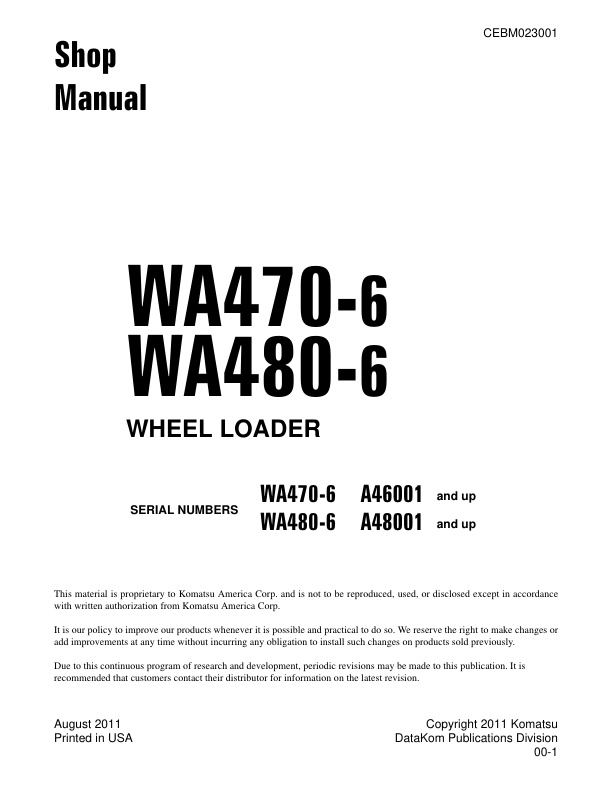
Komatsu WA470-6 A46001 & Up, WA480-6 A48001 & Up CEBM023001 (Preview)
CEBM023001 – WA470-6 – WA480-6
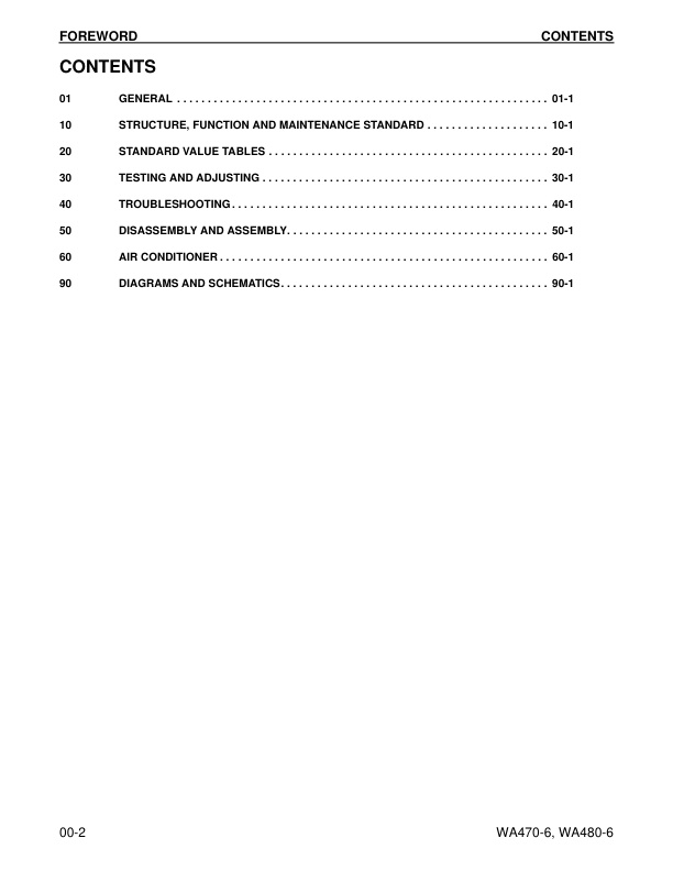
– CONTENTS
– REVISED PAGES
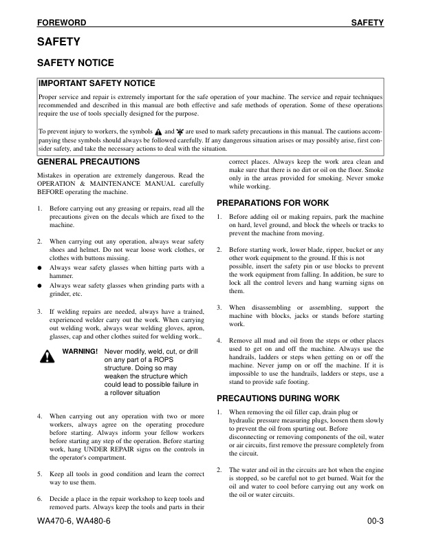
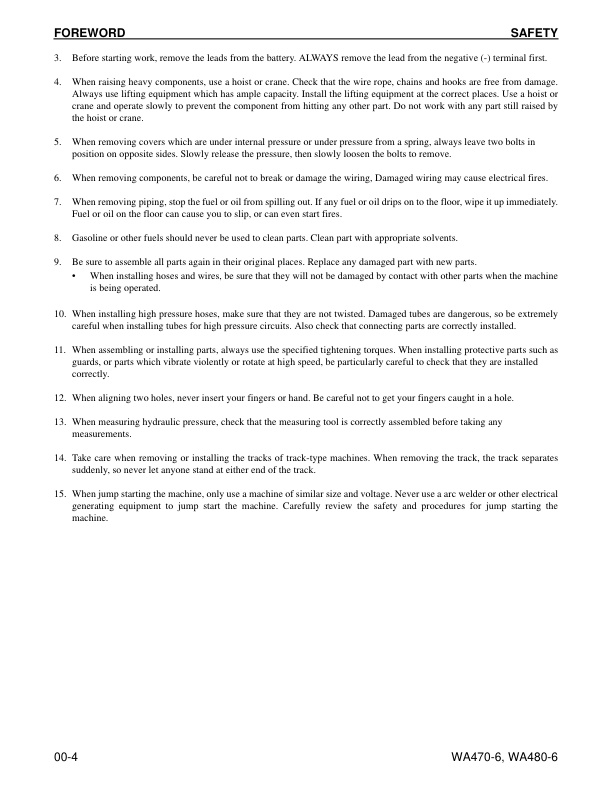
– SAFETY
— SAFETY NOTICE
— IMPORTANT SAFETY NOTICE
— GENERAL PRECAUTIONS
— PREPARATIONS FOR WORK
— PRECAUTIONS DURING WORK
– GENERAL
– HOW TO READ THE SHOP MANUAL
— VOLUMES
— DISTRIBUTION AND UPDATING
— FILING METHOD
— REVISED EDITION MARK
— REVISIONS
— SYMBOLS
– HOISTING INSTRUCTIONS
— HOISTING
— WIRE ROPES
– MAINTENANCE STANDARD TERMINOLOGY
– HANDLING ELECTRIC EQUIPMENT AND HYDRAULIC COMPONENTS
— Handling Connectors Used for Engines
— Slide Lock Type
— Pull Lock Type
— Push Lock Type
— Turn-housing Type (Round Green Connector)
– PRECAUTIONS FOR OPERATIONS
— Precautions when Carrying Out Removal Work
— Precautions when Carrying Out Installation Work
— Precautions when Completing the Operation
– PUSH PULL COUPLER
— TYPE 1
— DISCONNECTION
— CONNECTION
— TYPE 2
— DISCONNECTION
— CONNECTION
— TYPE 3
— DISCONNECTION
— CONNECTION
– COATING MATERIALS
– STANDARD TIGHTENING TORQUE
— STANDARD TIGHTENING TORQUE OF BOLTS AND NUTS
— TIGHTENING TORQUE OF HOSE NUTS
— TIGHTENING TORQUE OF SPLIT FLANGE BOLTS
— TIGHTENING TORQUE FOR FLARED NUTS
— TABLE OF TIGHTENING TORQUES FOR O-RING BOSS PIPING JOINTS
— TABLE OF TIGHTENING TORQUES FOR O-RING BOSS PLUGS
— TIGHTENING TORQUE TABLE FOR HOSES (TAPER SEAL TYPE AND FACE SEAL TYPE)
– ELECTRIC WIRE CODE
— CLASSIFICATION BY THICKNESS
— CLASSIFICATION BY COLOR AND CODE
– CONVERSION TABLES
— METHOD OF USING THE CONVERSION TABLE
– LIST OF ABBREVIATIONS
— List of Abbreviations Used in the Shop Manual
— List of Abbreviations Used in the Circuit Diagrams
01 GENERAL
– SPECIFICATIONS
— Dimension Drawing
— Specification Tables
– WEIGHT TABLE
– TABLE OF FUEL, COOLANT AND LUBRICANTS
10 STRUCTURE, FUNCTION ANDMAINTENANCE STANDARD
– ENGINE AND COOLING SYSTEM
— Engine and Transmission Mounting
— Cooling System
— Cooling Fan Pump
— Operation
— Servo Valve
— Cooling Fan Motor
— Hydraulic Motor
— Suction Valve
— Operation of Reversible Valve
— Safety Valve
– POWER TRAIN
— System Diagram
— Drive Shaft
— Power Train Piping Diagram
— Torque Converter
— Transmission
— Transmission control valve
— Left valve assembly
— Right valve assembly
— ECMV
– MAIN AND TORQUE CONVERTER RELIEF VALVES
– AXLE
— Front axle
— WA470-6
— WA480-6
— Rear axle
— WA470-6
— WA480-6
– DIFFERENTIAL
— Front Differential
— Rear Differential
– LIMITED SLIP DIFFERENTIAL
– FINAL DRIVE
– STEERING SYSTEM
— Steering System Layout Drawing
— Steering Column
— Steering Pump
— Pump Unit
— Steering Valve
— Orbit-roll Valve
— Stop Valve
— Steering Relief Valve
— Steering Cylinder
— Emergency steering motor
— Emergency Steering Pump
— Joystick Steering Lever Linkage
— Electrical Steering Lever
— Joystick EPC Valve
– BRAKE SYSTEM
— Brake Component Layout Drawing
— Charge Valve
— Brake Valve
— Accumulator (for brake)
— Slack Adjuster
— Brake
— Front Brake
— Rear Brake
— Parking Brake Control
— Parking Brake
— Parking Brake Solenoid Valve
— Emergency Parking Brake Release Valve
– UNDERCARRIAGE AND FRAME
— Axle Mount and Center Hinge Pin
— Tires
– HYDRAULIC SYSTEM
— Hydraulic Component Layout Drawing
— Work Equipment Control Lever Linkage
— Multi-Function Mono-lever Type
— Hydraulic Tank
— Breather
— Power Train Pump
— Work Equipment Pump
— Sectional View
— LS Valve
— PC Valve
— PC-EPC Valve
— Work Equipment Control Valve
— CLSS
— Basic principle
— Function and Operation of Each Valve
— Pressure Compensation Valve (Installed to cylinder head side of lift arm valve)
— Shuttle valve in the pressure compensation valve
— Supply of LS Pressure
— LS Bypass Plug
— ECSS Control Valve
— Accumulator Charge Valve
— PPC Valve
— Work Equipment PPC Valve
— Service PPC Valve (If equipped)
— Accumulator (for PPC circuit)
— Accumulator (for power train circuit)
— Accumulator (for ECSS) (If equipped)
— Work Equipment PPC Cut-off Solenoid Valve (If equipped)
– WORK EQUIPMENT
— Work Equipment Linkage
— Bucket Positioner And Boom Kick-out
— Work Equipment Cylinder
— Lift Cylinder
— Bucket Cylinder
– CAB AND ITS ATTACHMENTS
— Cab
— Air Conditioner
— Air Conditioner Piping Diagram
— Refrigerant Circuit Diagram
— Air Conditioner Unit
— Blower and Intake Unit
— Compressor
— Condenser
— Receiver
— Air conditioner panel
– ELECTRICAL SYSTEM
— Machine Monitor System
— System Circuit Diagram
— Machine Monitor
— Transmission Controller System
— Transmission Controller Gear Shifting Control Function
— System Circuit Diagram
— Transmission Controller
— Work Equipment Controller System
— System Circuit Diagram
— Work Equipment Controller
— Electric Transmission Control
— Combination Switch
— Kickdown Switch and Hold Switch
— Load Meter Cancel Switch and Load Meter Subtotal Switch
— Multi-function Knob
— Joystick Steering Knob
— KOMTRAX System
— KOMTRAX Terminal
— Engine Starting Circuit
— Engine Stopping Circuit
— Preheating Circuit
— Engine Power Mode Selector Circuit
— Engine Output Derating Function
— Automatic Warm-up Function
— Parking Brake Circuit
— Sensor
— Transmission Input Speed Sensor
— Transmission Output Speed Sensor
— Cooling Fan Speed Sensor
— Torque Converter Oil Temperature Sensor
— Hydraulic Oil Temperature Sensor
— Transmission Oil Temperature Sensor
— Brake Oil Temperature Sensor
— Work Equipment Pump Oil Pressure Sensor
— Steering Pump Oil Pressure Sensor
— Lift Cylinder Head Oil Pressure Sensor (machines equipped with load meter)
— Lift Cylinder Bottom Oil Pressure Sensor (machines equipped with load meter)
— Transmission Cut-off Oil Pressure Sensor
— Coolant Level Sensor
— Fuel Level Sensor
— Air Cleaner Clogging Sensor (machine equipped with KOMTRAX)
— Accelerator Pedal Sensor
— Boom Kick-out Proximity Switch
— Bucket Positioner Proximity Switch
— Lift Arm Potentiometer (machines equipped with load meter)
20 STANDARD VALUE TABLES
– STANDARD SERVICE VALUE TABLE
— Standard Service Value Table for Engine
— Standard Value Table For Chassis
— Machine Posture and Procedure for Performance Measurement
30 TESTING AND ADJUSTING
– TOOLS
— Tools For Testing, Adjusting, And Troubleshooting
– ENGINE COMPONENTS
— Engine Speed
— Exhaust Gas Color
— Exhaust Temperature
— Valve Clearance
— Compression Pressure
— Blow-by Pressure
— Engine Oil Pressure
— EGR Valve Drive Pressure
— Intake Air (Boost) Pressure
– FUEL SYSTEM
— Handling Fuel System Equipment
— Releasing Residual Pressure In Fuel System
— Fuel Pressure
— Fuel Return and Leak Amount
— Bleeding Air From Fuel Circuit.
— Fuel Circuit for Leakage
— Reduced Cylinder Mode Operation
— No Injection Cranking Operation
— Handling of Controller Voltage Circuit
– EXHAUST SYSTEM AND PIPING
— Check Muffler and Muffler Stack for Looseness and Damage
— Check Muffler Function
— Check Installed Condition of Cylinder Head and Manifolds
— Check Engine Piping for Damage and Looseness
– BELTS
— Air Conditioner Compressor Belt
— Testing
— Adjusting
— Adjusting Alternator Belt
— Testing
— Adjusting
– TRANSMISSION SPEED SENSOR
– DIRECTIONAL LEVER
— Adjusting Directional Lever Length
— Adjusting Gear Shift Lever Length
– FNR AND GEAR SHIFT LEVERS
— Testing FNR Lever and Gear Shift Lever
– POWER TRAIN OIL PRESSURE
— Testing and Adjusting Power Train Oil Pressure
— Measurement
— Adjustment
– FLUSHING TRANSMISSION SYSTEM
— Torque Converter and Transmission Hydraulic Circuit
– TRANSMISSION VALVE FAILS
— Moving Machine When Transmission Valve Is Broken
– AXLE DRIVE AND DRIVE SHAFTS
— Check Axle Final Drive for Oil Leakage
— Check Drive Shafts for Looseness, Play and Damage
– STEERING SYSTEM
— Steering Stop Valve
— Testing
— Adjusting
— Steering Wheel
— Steering Oil Pressure
— Bleeding Air From Steering Circuit
– HYDRAULIC FAN
— Hydraulic Drive Fan
— Hydraulic Fan Speed Sensor
— Bleeding Air From Hydraulic Drive Fan Circuit
– BRAKE SYSTEM
— Brake Pedal
— Brake Pedal Linkage
— Testing
— Adjusting
— Brake Performance
— Accumulator Charge Pressure
— Testing
— Adjusting
— W heel Brake Oil Pressure
— Check Wear of Wheel Brake Disc
— Bleed Air From Wheel Brake Circuit
— Release Residual Pressure in Brake Accumulator Circuit
— Parking Brake Performance
— Parking Brake Oil Pressure
— Wear Of Parking Brake Disc
— Manual Release for Parking Brake
– WORK EQUIPMENT
— Work Equipment Control Lever
— Work Equipment PPC Oil Pressure
— Measuring
— Adjusting
— Work Equipment Oil Pressure
— Testing
— Adjusting
— Bleeding Air From Work Equipment Circuit
— Releasing Residual Pressure in Work Equipment Circuit
– ACCUMULATOR
— Nitrogen Gas Accumulator Pressure of ECSS
— Testing
— Charging Accumulator
— Brake Accumulator Nitrogen Gas Pressure
— Testing
— Charging Accumulator
– BUCKET POSITIONER
— Testing
— Adjusting
– BOOM KICK-OUT
— Testing
— Adjusting
– PROXIMITY SWITCH OPERATION PILOT LAMP
– ELECTRICAL SYSTEM
— Diode Testing Procedure
— Electrical System Troubleshooting
– KOMTRAX SYSTEM
— How to Start KOMTRAX Terminal Operations
— Station Opening Check in Machine Side
— Application for the Start of Use
— Indicator Lamps of KOMTRAX Terminal
– MACHINE MONITOR SYSTEM
— Adjusting Replaced, Reassembled or Added Sensor, Controller, etc. WithMachine Monitor
— Special Functions of Machine Monitor (EMMS)
— Normal functions and special functions of machine monitor
— Functions and Flow of the Service Mode
— Operator Mode
— Service Meter/Clock Display Function (1)
— Load Meter Function (if equipped) (2)
— Odometer Display Function (3)
— Maintenance Monitoring Function (4)
— Telephone Number Input Function (5)
— Language Selection Function (6)
— Monitor Brightness Adjustment Function (7)
— Time Adjustment Function (8)
— Travel Speed/Engine Speed Display Selecting Function(9)
— Travel Speed/Engine Speed Display/Non-DisplaySelecting Function (10)
— Action Code Display Function (11)
— Failure Code Display Function (12)
— Service Mode
— Procedure For Switching To Service Mode And ScreenDisplay (1)
— Electrical System Fault History Display Function(ELECTRIC FAULT) (2)
— Mechanical System Fault History Display Function(MACHINE FAULT) (3)
— Real-Time Monitoring Function (REAL-TIME MONITOR)(4)
—- Real-Time Monitoring Code Table
— Engine Cylinder Cutout Function (CYLINDER CUTOUT)(5)
— No Injection Cranking Function (6)
— Adjustment Function (TUNING) (7)
— Maintenance Monitoring Function (8)
— Operating Information Display Function (9)
— OPTIONAL SELECT Function (10)
—- Optional component setting table
— Machine Serial Number Input Function (11)
— Machine Model Select Function (MACHINE) (12)
— Initialize Function (13)
– PM-CLINIC INSPECTION TABLE
— WA470-6 S/N A46001 and up
— WA480-6 S/N A48001 and up
40 TROUBLESHOOTING
– FAILURE CODE TABLE
— Fuse Locations
— Locations and Numbers of Fuse Boxes and Slow Blow Fuse
– POINTS TO REMEMBER WHEN TROUBLESHOOTING
– SEQUENCE OF EVENTS IN TROUBLESHOOTING
— Testing Before Troubleshooting
– CLASSIFICATION AND TROUBLESHOOTING PROCEDURES
– MODE CHART
— Information Contained in Troubleshooting Table
– CONNECTION TABLE FOR CONNECTOR PIN NUMBERS
— X-Type Connectors
— SWP-Type Connectors
— M-Type Connectors
— S-Type Connectors
— MIC-Type Connectors
— AMP040-Type Connectors
— AMP070-Type Connectors
— AMP Connector
— L-Type Connector
— PA-Type Connector
— Bendix (MS) Connector
— KES1 (Automobile) Connectors
— F-Type Connector
— HD30 Series Connectors
— DT Series Connectors
— DTM Series Connectors
— DTHD Series Connectors
— DTP Series Connectors
— DRC26 Series Connectors
— DRC12, 16 Series Connectors
— AMP Connectors for Pump Controller (CH700)
— BOSCH Connectors for Engine
— SUMITOMO Connectors for Engine
— CANNON Connector for Engine
— AMP Connectors for Engine
— FRAMATOME Connectors for Engine
— PACKARD Connectors for Engine
— DT Series Connectors for Engine
– T-BRANCH BOX and T-BRANCH ADAPTER TABLE
– FAILURE CODES
— 1500L0
— TORQFLOW Transmission: Double Meshing
— 15SAL1
— ECMV F Clutch: When Command Current is OFF, Fill Signal is ON
— 15SALH
— ECMV F Clutch: When Command Current is ON, Fill Signal is OFF
— 15SBL1
— ECMV R Clutch: When Command Current is OFF, Fill Signal is ON
— 15SBLH
— ECMV R Clutch: When Command Current is ON, Fill Signal is OFF
— 15SEL1
— ECMV 1st Clutch: When Command Current is OFF, Fill Signal is ON
— 15SELH
— ECMV 1st Clutch: When Command Current is ON, Fill Signal is OFF
— 15SFL1
— ECMV 2nd Clutch: When Command Current is OFF, FIll Signal is ON
— 15SFLH
— ECMV 2nd Clutch: When Command Current is ON, Fill Signal is OFF
— 15SGL1
— ECMV 3rd Clutch: When Command Current is OFF, Fill Signal is ON
— 15GLH
— ECMV 3rd Clutch: When Command Current is ON, Fill Signal is OFF
— 15SHL1
— ECMV 4th Clutch: When Command Current is OFF, Fill Signal is ON
— 15SHLH
— ECMV 4th Clutch: When Command Current is ON, Fill Signal is OFF
— 2F00MA
— Parking Brake: Malfunction
— 2G43ZG
— Accumulator: Low Oil Pressure
— 44K0L4
— Bucket Positioner: ON/OFF Signals Disagree
— AA1ANX
— Air Cleaner: Clogging
— AB00L6
— Alternator: Signal Disagrees with Operating State of Engine
— AB00MA
— Alternator: Malfunction
— B@BAZG
— Engine: Rotation Derating by Low Engine Oil Pressure
— B@BAZK
— Engine Oil: Low Level
— B@BCNS
— Coolant: Overheating
— B@BCZK
— Engine Coolant: Low Level
— B@C7NS
— Brake Oil: Overheating
— b@CENS
— Torque Converter Oil: Overheating
— B@CENS
— Torque Converter Oil: Overheating
— B@HANS
— Hydraulic Oil: Overheating
— CA111
— Abnormality in Engine Controller
— CA115
— Engine Ne or Bkup Speed Sensor Error
— CA122
— Charge Pressure Sensor High Error
— CA123
— Charge Pressure Sensor Low Error
— CA131
— Throttle Sensor High Error
— CA132
— Throttle Sensor Low Error
— CA135
— Engine Oil Pressure Sensor High Error
— CA141
— Engine Oil Pressure Sensor Low Error
— CA144
— Coolant Sensor High Error
— CA145
— Coolant Temperature Sensor Low Error
— CA153
— Charge Temperature Sensor High Error
— CA154
— Charge Temperature Sensor Low Error
— CA187
— Sensor Power Supply 2 Low Error
— CA221
— Atmospheric Pressure Sensor High Error
— CA222
— Atmospheric Pressure Sensor Low Error
— CA227
— Sensor Power Supply 2 High Error
— CA234
— Engine Overspeed
— CA238
— NE Speed Sensor Power Supply Error
— CA263
— Fuel Temperature Sensor High Error
— CA265
— Fuel Temperature Sensor Low Error
— CA271
— PCV1 Short Circuit
— CA272
— PCV1 Disconnection
— CA273
— PCV2 Short Circuit
— CA274
— PCV2 Disconnection
— CA322
— Injector #1 Open/Short Error
— CA323
— Injector #5 Open/Short Error
— CA324
— Injector #3 Open/Short Error
— CA325
— Injector #6 Open/Short Error
— CA331
— Injector #2 Open/Short Error
— CA332
— Injector #4 Open/Short Error
— CA342
— Calibration Code Inconsistency
— CA351
— Injectors Drive Circuit Error
— CA352
— Sensor Power Supply 1 Low Error
— CA386
— Sensor Power Supply 1 High Error
— CA431
— Idle Validation Switch Error
— CA432
— Idle Validation Action Error
— CA441
— Battery Voltage Low Error
— CA442
— Battery Voltage High Error
— CA449
— Common Rail Pressure High Error 2
— CA451
— Common Rail Pressure Sensor High Error
— CA452
— Common Rail Pressure Sensor Low Error
— CA553
— Common Rail Pressure High Error 1
— CA554
— Common Rail Pressure Sensor In-Range Error
— CA559
— Supply Pump Pressure Very Low Error
— CA689
— Engine Ne Speed Sensor Error
— CA731
— Engine Bkup Speed Sensor Phase Error
— CA757
— All Continuous Data Lost Error
— CA778
— Engine Bkup Speed Sensor Error
— CA1228
— EGR Valve Servo Error 1
— CA1625
— EGR Valve Servo Error 2
— CA1633
— KOMNET Datalink Timeout Error
— CA2185
— Throttle Sensor Supply Voltage High Error
— CA2186
— Throttle Sensor Power Supply Low Error
— CA2249
— Supply Pump Pressure Very Low Error 2
— CA2271
— EGR Valve Lift Sensor High Error
— CA2272
— EGR Valve Lift Sensor Low Error
— CA2351
— EGR Valve Solenoid Operation Short Circuit
— CA2352
— EGR Valve Solenoid Operation Disconnect
— CA2555
— Intake Heater Relay Disconnection Error
— CA2556
— Intake Heater Relay Short Circuit Error
— D150KA
— Emergency Steering Relay: Disconnection
— D150KB
— Emergency Steering Relay: Short Circuit
— D150KY
— Emergency Steering Relay: Short Circuit With Power Supply Line
— D160KA
— Backup Lamp Relay Output: Disconnection
— D160KB
— Backup Lamp Relay Output: Short Circuit
— D191KA
— Joystick Steering Neutral Safety Relay: Disconnection
— D191KB
— Joystick Steering Neutral Safety Relay: Short Circuit
— D191KY
— Joystick Steering Neutral Safety Relay: Short Circuit With Power Supply Line
— D192KA
— ECSS Solenoid: Disconnection
— D192KB
— ECSS Solenoid: Short Circuit
— D192KY
— ECSS Solenoid: Short Circuit With Power Supply Line
— D193KA
— Joystick Steering Solenoid Cut-Off Relay: Disconnection
— D193KB
— Joystick steering solenoid cut-off relay: Short circuit
— D193KY
— Joystick Steering Solenoid Cut-Off Relay: Short Circuit With Power Supply Line
— D5ZHKA
— Terminal C Signal: Disconnection
— D5ZHKB
— Terminal C Signal: Short Circuit
— D5ZHKZ
— Terminal C Signal: Disconnection Or Short Circuit
— D5ZHL6
— Terminal C Signal: Signal Does Not Match Engine Running Or Stopped State
— DA80L4
— Auto Grease Controller: ON/OFF Signals Disagree
— DAF3KK
— Machine Monitor: Low Source Voltage (Input)
— DAF5KP
— Machine Monitor: Low Output Voltage
— DAFRKR
— CAN Communication With Machine Monitor: Defective Communication (Abnormality In Target Component System)
— DAQ0KK
— Transmission Controller: Low Source Voltage
— DAQ0KT
— Transmission Controller: Abnormality In Controller
— DAQ1KA
— Terminal ACC Input: Disconnection
— DAQ2KK
— Transmission Controller Load Power Supply Line: Low Source Voltage (Input)
— DAQ9KQ
— Transmission Controller Model Selection: Disagreement of Model Selection Signals
— DAQRKR
— CAN Communication with Transmission Controller: Defective Communication (Abnormality in Target Component System)
— DAQRMA
— Transmission Controller Option Setting: Malfunction
— DB2RKR
— CAN Communication with Engine Controller: Defective Communication (Abnormality in Target Component System)
— DB90KK
— Work Equipment Controller: Low Source Voltage (Input)
— DB90KT
— Work Equipment Controller: Abnormality in Controller
— DB92KK
— Work Equipment Controller Load Power Supply Line: Low Source Voltage (Input)
— DB95KX
— Work Equipment Controller Power Supply Output: Out of Input Signal Range
— DB99KQ
— Work Equipment Controller Model Selection: Disagreement in Model Selection Signals
— DB9RKR
— CAN Communication With Work Equipment Controller: Defective Communication (Abnormality in Target Component System)
— DB9RMA
— Work equipment controller option setting: Malfunction
— DB9RMC
— CAN Communication With Transmission Controller, Engine Controller and Machine Monitor: Defective Operation
— DD15LD
— n Switch (Panel Switch 1): Switch Is Kept Pressed For Long Time
— DD16LD
— Ø Switch (Panel Switch 2): Switch is Kept Pressed for Long Time
— DD17LD
— < Switch (Panel Switch 3): Switch Is Kept Pressed For Long Time
-- DD18LD
--- > Switch (Panel Switch 4): Switch Is Kept Pressed For Long Time
— DD1ALD
— Remote Positioner Raise/lower Set Switch (Raise): Switch Is Kept Pressed For Long Time
— DD1BLD
— Remote Positioner Raise/lower Set Switch (Lower): Switch Is Kept Pressed For Long Time
— DD1CLD
— Load Meter Subtotal Switch: Switch Is Kept Pressed For Long Time
— DD1FLD
— Load Meter Mode Selector Switch (A/B): Switch Is Kept Pressed For Long Time
— DD1GLD
— Load Meter Mode Selector Switch (+/-): Switch Is Kept Pressed For Long Time
— DD1HLD
— Load Meter Display Selector Switch: Switch Is Kept Pressed For Long Time
— DD1NLD
— Fan Reverse Switch: Switch Is Kept Pressed For Long Time
— DD1NL4
— Fan Automatic Reverse Switch: Switch Is Kept Pressed For Long Time
— DDB6L4
— Parking Brake Switch (Neutralizer): ON/OFF Signals Disagree
— DDD1LD
— Remote Positioner Bucket Angle Set Switch: Switch Is Kept Pressed For Long Time
— DDE5MA
— Emergency Steering Drive Switch: Malfunction
— DDK3KA
— Right FNR Switch: Disconnection
— DDK4KA
— Joystick Steering FNR Switch: Disconnection
— DDK5L4
— Joystick Steering Shift-Up/Down Switch: ON/OFF Signals Disagree
— DDK6KA
— FNR Lever Switch: Disconnection
— DDK6KB
— FNR Lever Switch: Short Circuit
— DDS5KA
— Steering Pressure Switch Signal: Disconnected
— DDS5KB
— Steering pressure Switch Signal: Short Circuit
— DDS5L6
— Steering: Low Oil Pressure
— DDT0L4
— Shift Mode Selector Switch: ON/OFF Signals Disagree
— DDT4LD
— Transmission Cut-Off Set Switch: Switch Is Kept Pressed For Long Time
— DDW9LD
— Kick-Down Switch: Switch Is Kept Pressed For Long Time
— DDWLLD
— Hold Switch: Switch Is Kept Pressed For Long Time
— DDY0LD
— Load Meter Cancel Switch: Switch Is Kept Pressed For Long Time
— DF10KA
— Transmission Shift Lever Switch: Disconnected
— DF10KB
— Transmission Shift Lever Switch: Short Circuit
— DGF1KA
— Transmission Oil Temperature Sensor: Disconnected
— DGF1KB
— Transmission Oil Temperature Sensor: Short Circuit
— DGH2KX
— Hydraulic Oil Temperature Sensor: Out Of Input Signal Range
— DGR2KA
— Rear Brake Oil Temperature Sensor: Disconnected
— DGR2KX
— Rear Brake Oil Temperature Sensor: Out Of Input Signal Range
— DGT1KX
— Torque converter oil temperature sensor: Out of input signal range
— DH21KA
— Loader Pump Pressure Sensor: Disconnection
— DH21KB
— Loader Pump Pressure Sensor: Power Supply Line Short
— DHPCKX
— Lift Arm Cylinder Bottom Pressure Sensor: Out Of Input Signal Range
— DHPDKX
— Lift Arm Cylinder Head Pressure Sensor: Out Of Input Signal Range
— DHT1KX
— Transmission Cut-Off Pressure Sensor: Out Of Input Signal Range
— DHT8KA
— Steering Pump Pressure Sensor: Disconnection
— DHT8KB
— Steering Pump Pressure Sensor: Short Circuit
— DK59KA
— Lift Arm EPC Lever Potentiometer (Main): Disconnection
— DK59KY
— Lift Arm EPC Lever Potentiometer (Main): Short Circuit With Power Supply Line
— DK59L8
— Lift Arm EPC Lever Potentiometer (Main): Analog Signals Disagree
— DK5AKA
— Lift Arm EPC Lever Potentiometer (Sub): Disconnection
— DK5AKY
— Lift Arm EPC Lever Potentiometer (Sub): Short Circuit With Power Supply Line
— DK5BKA
— Bucket EPC Lever Potentiometer (Main): Disconnection
— DK5BKY
— Bucket EPC Lever Potentiometer (Main): Short Circuit With Power Supply Line
— DK5BL8
— Bucket EPC Lever Potentiometer (Main): Analog Signals Disagree
— DK5CKA
— Bucket EPC Lever Potentiometer (Sub): Disconnection
— DK5CKY
— Bucket EPC Lever Potentiometer (Sub): Short Circuit With Power Supply Line
— DK5FKA
— Joystick Steering EPC Lever Potentiometer (Main): Disconnection
— DK5FKY
— Joystick steering EPC lever potentiometer (Main): Short circuit with power supply line
— DK5GKA
— Joystick Steering EPC Lever Potentiometer (Sub): Disconnection
— DK5GKY
— Joystick Steering EPC Lever Potentiometer (Sub): Short Circuit With Power Supply Line
— DK5FL8
— Joystick Steering EPC Lever Potentiometer (Main): Analog Signals Disagree
— DKA0KA
— Lift Arm Angle Sensor: Disconnection
— DKA0KY
— Lift Arm Angle Sensor: Short Circuit With Power Supply Line
— DKA0L0
— Lift Arm Angle Sensor: Double Meshing
— DLF1KA
— Transmission Input Speed Sensor: Disconnection
— DLF1LC
— Transmission Input Speed Sensor: Short Circuit
— DLM3KA
— Fan Speed Sensor: Disconnection
— DLM3LC
— Fan Speed Sensor: Short Circuit
— DLT3KA
— Transmission Output Speed Sensor: Disconnection
— DLT3LC
— Transmission Output Speed Sensor: Out Of Input Signal Range
— DT20KB
— Transmission Cut-Off Indicator Lamp: Short Circuit
— DUM1KB
— Remote Positioner Raise Set Indicator Lamp: Short Circuit
— DUM2KB
— Remote Positioner Lower Set Indicator Lamp: Short Circuit
— DV00KB
— Alarm Buzzer: Short Circuit
— DW4PKA
— Lift Arm Raise EPC Solenoid: Disconnection
— DW4PKB
— Lift Arm Raise EPC Solenoid: Short Circuit
— DW4PKY
— Lift Arm Raise EPC Solenoid: Short Circuit With Power Supply Line
— DW4QKA
— Lift Arm Lower EPC Solenoid: Disconnection
— DW4QKB
— Lift Arm Lower EPC Solenoid: Short Circuit
— DW4QKY
— Lift Arm Lower EPC Solenoid: Short Circuit With Power Supply Line
— DW4RKA
— Bucket Tilt EPC Solenoid: Disconnection
— DW4RKB
— Bucket Tilt EPC Solenoid: Short Circuit
— DW4RKY
— Bucket Tilt EPC Solenoid: Short Circuit With Power Supply Line
— DW4SKA
— Bucket Dump EPC Solenoid: Disconnection
— DW4SKB
— Bucket Dump EPC Solenoid: Short Circuit
— DW4SKY
— Bucket Dump EPC Solenoid: Short Circuit With Power Supply Line
— DW7BKA
— Fan Reverse Solenoid: Disconnection
— DW7BKB
— Fan Reverse Solenoid: Short Circuit
— DW7BKY
— Fan Reverse Solenoid: Short Circuit With Power Supply Line
— DWM1KA
— Work Equipment Neutral Lock Solenoid: Disconnection
— DWM1KB
— Work Equipment Neutral Lock Solenoid: Short Circuit
— DWM1KY
— Work Equipment Neutral Lock Solenoid: Short Circuit With Power Supply Line
— DWN6KA
— Lift Arm Raise Magnet Detent Solenoid: Disconnection
— DWN6KB
— Lift Arm Raise Magnet Detent Solenoid: Short Circuit
— DWN6KY
— Lift Arm Raise Magnet Detent Solenoid: Short Circuit With Power Supply Line
— DWN7KA
— Lift Arm Float Magnet Detent Solenoid: Disconnection
— DWN7KB
— Lift Arm Float Magnet Detent Solenoid: Short Circuit
— DWN7KY
— Lift Arm Float Magnet Detent Solenoid: Short Circuit With Power Supply Line
— DWN8KA
— Bucket Tilt Magnet Detent Solenoid: Disconnection
— DWN8KB
— Bucket Tilt Magnet Detent Solenoid: Short Circuit
— DWN8KY
— Bucket Tilt Magnet Detent Solenoid: Shorted With The Power Source
— DX16KA
— Fan Pump EPC Solenoid: Disconnection
— DX16KB
— Fan Pump EPC Solenoid: Short Circuit
— DX16KY
— Fan Pump EPC Solenoid: Short Circuit With Power Supply Line
— DXA1KA
— Loader Pump PC-EPC Solenoid: Disconnection
— DXA1KB
— Loader Pump PC-EPC Solenoid: Short Circuit
— DXANKA
— Steering Pump PC-EPC Solenoid: Disconnection
— DXANKB
— Steering Pump PC-EPC Solenoid: Short Circuit
— DXH1KA
— Lockup ECMV Solenoid: Disconnection
— DXH1KB
— Lockup ECMV Solenoid: Short Circuit
— DXH1KY
— Lockup ECMV Solenoid: Short Circuit With Power Supply Line
— DXH4KA
— 1st Clutch ECMV Solenoid: Disconnection
— DXH4KB
— 1st Clutch ECMV Solenoid: Short Circuit
— DXH4KY
— 1st Clutch ECMV Solenoid: Short Circuit With Power Supply Line
— DXH5KA
— 2nd Clutch ECMV Solenoid: Disconnection
— DXH5KB
— 2nd Clutch ECMV Solenoid: Short Circuit
— DXH5KY
— 2nd Clutch ECMV Solenoid: Short Circuit With Power Supply Line
— DXH6KA
— 3rd Clutch ECMV Solenoid: Disconnection
— DXH6KB
— 3rd cluTch ECMV Solenoid: Short Circuit
— DXH6KY
— 3rd Clutch ECMV Solenoid: Short Circuit With Power Supply Line
— DXH7KA
— R Clutch ECMV Solenoid: Disconnection
— DXH7KB
— R Clutch ECMV Solenoid: Short Circuit
— DXH7KY
— R Clutch ECMV Solenoid: Short Circuit With Power Supply Line
— DXH8KA
— F Clutch ECMV Solenoid: Disconnection
— DXH8KB
— F Clutch ECMV Solenoid: Short Circuit
— DXH8KY
— F Clutch ECMV Solenoid: Short Circuit With Power Supply Line
— DXHHKA
— 4th Clutch ECMV Solenoid: Disconnection
— DXHHKB
— 4th Clutch ECMV Solenoid: Short Circuit
— DXHHKY
— 4th Clutch ECMV Solenoid: Short Circuit With Power Supply Line
— DXHLKA
— Joystick Steering Right EPC Solenoid: Disconnection
— DXHLKB
— Joystick Steering Right EPC Solenoid: Short Circuit
— DXHLKY
— Joystick steering right EPC solenoid: Short circuit with power supply line
— DXHMKA
— Joystick Steering Left EPC Solenoid: Disconnection
— DXHMKB
— Joystick Steering Left EPC Solenoid: Short Circuit
— DXHMKY
— Joystick Steering Left EPC Solenoid: Short Circuit With Power Supply Line
— DY30MA
— Motor-Driven Emergency Steering Pump Failure (During Operation Of Machine)
— DY30MC
— Motor-Driven Emergency Steering Pump Failure (Malfunction In Manual Mode)
— DY30ME
— Emergency Steering: Operating For More Than 1 Minute
– E MODE
— E-1
— Engine Does Not Start
— E-2
— Wiper does not operate
— E-3
— Windshield Washer Does Not Operate
— E-4
— Headlamp, Clearance Lamp, Tail Lamp, And License Lamp Do Not Light Up Or Go Off
— E-5
— Working Lamp Does Not Light Up Or Go Off
— E-6
— Turn Signal Lamp And Hazard Lamp Do Not Light Up Or Go Off
— E-7
— Brake Lamp Does Not Light Or It Keeps Lighting Up
— E-8
— Backup Lamp Does Not Light Or It Keeps Lighting Up
— E-9
— Backup Buzzer Does Not Sound Or It Keeps Sounding
— E-10
— Horn Does Not Sound Or It Keeps Sounding
— E-11
— Alarm buzzer does not sound or it keeps sounding
— E-12
— Air Conditioner Does Not Operate Or Stop
— E-13
— The KOMTRAX System Does Not Work Properly
— E-14
— When Kick-down Switch Is Turned ON, Kick-down Operation Does Not Start
— E-15
— When Hold Switch Is Pressed, Holding Operation Does Not Start
— E-16
— Transmission Is Kept In Neutral, Or Brake Drags When Directional Lever Is Operated While Parking Brake Is Applied
— E-17
— Transmission Cut-off Mode Cannot Be Set Or Reset
— E-18
— Transmission Cut-off Set Cannot Be Reset
— E-19
— FNR Switch Mode Cannot Be Set Or Reset
— E-20
— Fan Reverse Function Cannot Be Used Or Reset
— E-21
— Discharge From Loader Pump Does Not Rise From Minimum Level
— E-22
— ECSS Function Cannot Be Used Or Reset
— E-23
— When Parking Brake Is Turned ON, Parking Brake Indicator Lamp Does Not Light Up
— E-24
— When Emergency Brake Operates, Brake Oil Pressure Caution Lamp Does Not Operate
— E-25
— Air Cleaner Clogging Indicator Lamp Does Not Light Up
— E-26
— Radiator Coolant Level Caution Lamp Does Not Light Up
— E-27
— Hydraulic Oil Temperature Gauge Does Not Rise And Hydraulic Oil Temperature Caution Lamp Does Not Light Up
— E-28
— Torque Converter Oil Temperature Gauge Does Not Rise And Torque Converter Oil Temperature Caution Lamp Does Not Light Up
— E-29
— Steering Oil Pressure Caution Lamp Does Not Light Up
— E-30
— Abnormality In n Switch (Panel Switch 1) Input
— E-31
— Abnormality In ‡ Switch (Panel Switch 1) Input
— E-32
— Abnormality In < Switch (Panel Switch 2) Input
-- E-33
--- Abnormality In > Switch (Panel Switch 2) Input
– H-MODE HYDRAULIC AND MECHANICAL SYSTEM
— Method Of Using Troubleshooting Chart
— Table Of Failure And Causes
— H-1
— The Machine Does Not Start
— H-2
— Torque Converter Lockup Is Not Switched Off (Engine Stalls) [Machine With Lockup Clutch (If Equipped)]
— H-3
— Torque Converter Lockup Is Not Switched On [Machine With Lockup Clutch (If Equipped)]
— H-4
— The Travel Speed Is Slow, The Thrusting Force Is Weak, The Uphill Traveling Power Is Weak, And The Gear Is Not Shifted
— H-5
— Shocks Are Large At The Times Of Starting And Shifting Gear
— H-6
— Time Lag Is Large At The Times Of Starting And Shifting Gear
— H-7
— The Torque Converter Oil Temperature Is High
— H-8
— Steering Does Not Turn
— H-9
— Steering Does Not Turn [Machine With Joystick Steering (If Equipped)]
— H-10
— Steering Response Is Poor
— H-11
— Turning, Response Of Steering Is Poor [Machine With Joystick Steering (If Equipped)]
— H-12
— Steering Is Heavy
— H-13
— When Machine Turns, It Shakes Or Makes Large Shocks
— H-14
— When Machine Turns, It Shakes Or Makes Large Shocks [Machine With Joystick Steering (If Equipped)]
— H-15
— The Wheel Brake Does Not Work Or Does Not Work Well
— H-16
— The Wheel Brake Is Not Released Or It Drags
— H-17
— The Parking Brake Does Not Work Or Does Not Work Well
— H-18
— The Parking Brake Is Not Released Or It Drags (Including Emergency Release System)
— H-19
— Lift Arm Does Not Rise
— H-20
— LIft Arm Speed Is Low Or Rising Force Of Lift Arm Is Insufficient
— H-21
— When Rising, The Lift Arm Comes To Move Slowly At Specific Height
— H-22
— The Lift Arm Cylinder Cannot Hold Down The Bucket (Bucket Floats)
— H-23
— Hydraulic Drift Of The Lift Arm Is Large
— H-24
— The Lift Arm Wobbles During Operation
— H-25
— Bucket Does Not Tilt Back
— H-26
— Bucket Speed Is Low Or Tilting Back Force Is Insufficient
— H-27
— The Bucket Comes To Operate Slowly In The Midst Of Tilting-back
— H-28
— The Bucket Cylinder Cannot Hold Down The Bucket
— H-29
— Hydraulic Drift Of The Bucket Is Large
— H-30
— The Bucket Wobbles During Travel With Cargo (The Work Equipment Valve Is Set To “Hold”)
— H-31
— Lift Arm And Bucket Control Levers Do Not Move Smoothly And Are Heavy
— H-32
— During Operation Of The Machine, Engine Speed Lowers Remarkably Or Engine Stalls
— H-33
— Large Shock Is Made When Work Equipment Starts And Stops
— H-34
— When Work Equipment Circuit Is Relieved Singly, Other Work Equipment Moves
— H-35
— ECSS Does Not Operate, And Pitching, Bouncing Occur
50 DISASSEMBLY AND ASSEMBLY
– HOW TO READ THIS MANUAL
— Removal And Installation Of Assemblies
— Special Tools
— Removal
— Installation
— Disassembly And Assembly Of Assemblies
— Special Tools
— Disassembly
— Assembly
– SPECIAL TOOLS LIST
— Sketches of special tools
– CONNECTOR REPAIR PROCEDURES
— Stripping Insulation
— Wire Inspection
— Contact Terminal Removal (HD30 Type)
— Crimping Contact Terminal (HD30 Type)
— Insertion Of Contact Terminal (HD30 Type)
— Contact Terminal Removal (DT Type)
— Crimping Contact Terminal (DT Type)
— Insertion Of Contact Terminal (DT Type)
– ENGINE AND COOLING SYSTEM
— Engine
— Removal
— Installation
— Engine Hood
— Removal
— Installation
— Radiator
— Removal
— Installation
— Aftercooler
— Removal
— Installation
— Oil Cooler
— Removal
— Installation
— Cooling Fan And Drive Motor
— Removal
— Installation
— Fuel Supply Pump
— Removal
— Installation
— Fuel Injector
— Removal
— Installation
— Cylinder Head
— Removal
— Installation
— Engine Front Oil Seal
— Removal
— Installation
— Engine Rear Oil Seal
— Removal
— Installation
— Fuel Tank
— Removal
— Installation
– POWER TRAIN
— Torque Converter And Transmission
— Removal
— Installation
— Disassembly
— Assembly
— Torque Converter (Standard Specification)
— Disassembly
— Assembly
— Torque Converter (Lockup Specification)
— Disassembly
— Assembly
— Clutch Pack
— Disassembly
— Assembly
— Front Axle
— Removal
— Installation
— Rear Axle
— Removal
— Installation
— Axle Housing
— Disassembly
— Assembly
— Differential
— Disassembly
— Assembly
– BRAKE SYSTEM
— Parking Brake Disc And Plate
— Removal
— Installation
– UNDERCARRIAGE AND FRAME
— Center Hinge Pin
— Removal
— Installation
— Counterweight
— Removal
— Installation
– HYDRAULIC SYSTEM
— Steering Demand Valve
— Removal
— Installation
— Work Equipment Valve
— Removal
— Installation
— Brake Charge Valve
— Removal
— Installation
— Hydraulic Tank
— Removal
— Installation
— Steering And Power Train Pump
— Removal
— Installation
— Work Equipment and Cooling Fan Pump
— Removal
— Installation
— Hydraulic Cylinder
— Disassembly
— Assembly
– WORK EQUIPMENT
— Removal
— Installation
– CAB AND ITS ATTACHMENTS
— Operator’s Cab And Floor Frame
— Removal
— Installation
— Operator’s Cab Glass (Stuck Glass)
— Removal
— Installation
— Operator’s Seat
— Disassembly
— Assembly
— Manufactured By GRAMMER (Seat)
— Upper Seat
— Suspension
— Air Conditioner Unit
— Removal
— Engine Controller
— Removal
— Installation
— Transmission Controller
— Removal
— Installation
— KOMTRAX Terminal
— Removal
— Installation
60 AIR CONDITIONER
– PRECAUTIONS FOR REFRIGERANT
– TROUBLESHOOTING PROCEDURE
— Basic Flow Of Troubleshooting
– CIRCUIT DIAGRAM AND CONNECTOR PINS
– SYSTEM DIAGRAM
– DETAIL OF AIR CONDITIONER UNIT
— Parts and Connectors Layout
— Testing wIth Self-Diagnosis Function (Control Panel Display)
— Testing Temperature Control
— Testing Vent (Mode) Changeover
— Testing Fresh/Recirc Changeover
— Testing Inside and Outside Air Temp. Sensor
— Testing Evaporator Temperature Sensor
— Testing Sunlight Sensor
— Testing Relays 1
– TROUBLESHOOTING CHART 1
– TROUBLESHOOTING CHART 2
– INFORMATION IN TROUBLESHOOTING TABLE
– TROUBLESHOOTING FOR POWER
— Air Conditioner Does Not Operate
– TROUBLESHOOTING COMPRESSOR AND REFRIGERANT SYSTEM
— Air Is Not Cooled
– TROUBLESHOOTING FOR BLOWER MOTOR
— No Air Comes Out Or Air Flow Is Abnormal
– TROUBLESHOOTING TEMPERATURE CONTROL
– TROUBLESHOOTING VENT (MODE) CHANGEOVER
— Machine Equipped With Automatic Air Conditioner
– TROUBLESHOOTING FRESH/RECIRC AIR CHANGEOVER
— Machine Equipped With Automatic Air Conditioner
– TROUBLESHOOTING WITH GAUGE PRESSURE
– CONNECTION OF SERVICE TOOL.
– HANDLING OF COMPRESSOR OIL
90 DIAGRAMS AND SCHEMATICS
– POWER TRAIN HYDRAULIC CIRCUIT DIAGRAM
— Without Lockup Clutch
— With Lockup Clutch
– AUTOMATIC GREASING CIRCUIT DIAGRAM
– Hydraulic Circuit Diagram
– Electrical Circuit Diagram (1/10)
– Electrical Circuit Diagram (2/10)
– Electrical Circuit Diagram (3/10)
– Electrical Circuit Diagram (4/10)
– Electrical Circuit Diagram (5/10)
– Electrical Circuit Diagram (6/10)
– Electrical Circuit Diagram (7/10)
– Electrical Circuit Diagram (8/10)
– Electrical Circuit Diagram (9/10)
– Electrical Circuit Diagram (10/10)
– Work Equipment Controller System Electrical Circuit Diagram
– Connector List and Stereogram
Reviews
There are no reviews yet.