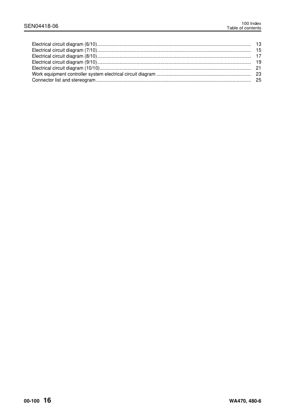
Komatsu WA470-6, WA480-6 90001 & Up SEN04409-06 (Preview)
COVER
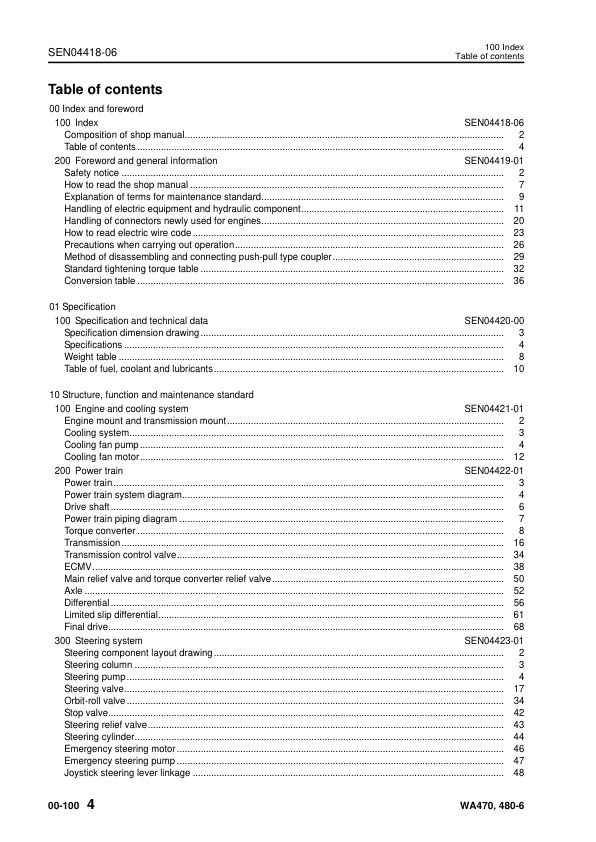
00 Index and foreword
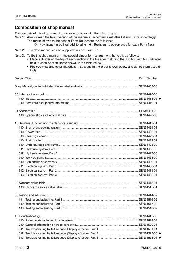
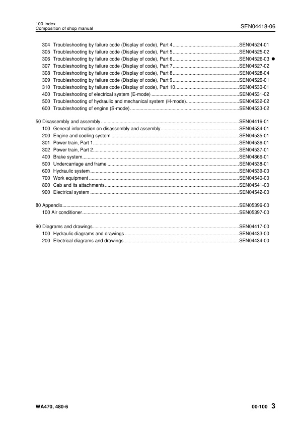
– 100 Index
— Composition of shop manual
— Table of contents
– 200 Foreword and general information
— Safety notice
— How to read the shop manual
— Explanation of terms for maintenance standard
— Handling of electric equipment and hydraulic component
— Handling of connectors newly used for engines
— How to read electric wire code
— Precautions when carrying out operation
— Method of disassembling and connecting push-pull type coupler
— Standard tightening torque table
— Conversion table
01 Specification
– 100 Specification and technical data
— Specification dimension drawing
— Specifications
— Weight table
— Table of fuel, coolant and lubricants
10 Structure, function and maintenance standard
– 100 Engine and cooling system
— Engine mount and transmission mount
— Cooling system
— Cooling fan pump
— Cooling fan motor
– 200 Power train
— Power train
— Power train system diagram
— Drive shaft
— Power train piping diagram
— Torque converter
— Transmission
— Transmission control valve
— ECMV
— Main relief valve and torque converter relief valve
— Axle
— Differential
— Limited slip differential
— Final drive
– 300 Steering system
— Steering component layout drawing
— Steering column
— Steering pump
— Steering valve
— Orbit-roll valve
— Stop valve
— Steering relief valve
— Steering cylinder
— Emergency steering motor
— Emergency steering pump
— Joystick steering lever linkage
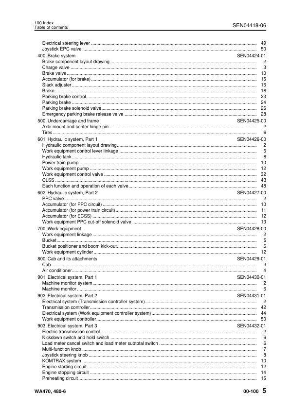
— Electrical steering lever
— Joystick EPC valve
– 400 Brake system
— Brake component layout drawing
— Charge valve
— Brake valve
— Accumulator (for brake)
— Slack adjuster
— Brake
— Parking brake control
— Parking brake
— Parking brake solenoid valve
— Emergency parking brake release valve
– 500 Undercarriage and frame
— Axle mount and center hinge pin
— Tires
– 601 Hydraulic system, Part 1
— Hydraulic component layout drawing
— Work equipment control lever linkage
— Hydraulic tank
— Power train pump
— Work equipment pump
— Work equipment control valve
— CLSS
— Each function and operation of each valve
– 602 Hydraulic system, Part 2
— PPC valve
— Accumulator (for PPC circuit)
— Accumulator (for power train circuit)
— Accumulator (for ECSS)
— Work equipment PPC cut-off solenoid valve
– 700 Work equipment
— Work equipment linkage
— Bucket
— Bucket positioner and boom kick-out
— Work equipment cylinder
– 800 Cab and its attachments
— Cab
— Air conditioner
– 901 Electrical system, Part 1
— Machine monitor system
— Machine monitor
– 902 Electrical system, Part 2
— Electrical system (Transmission controller system)
— Transmission controller
— Electrical system (Work equipment controller system)
— Work equipment controller
– 903 Electrical system, Part 3
— Electric transmission control
— Kickdown switch and hold switch
— Load meter cancel switch and load meter subtotal switch
— Multi-function knob
— Joystick steering knob
— KOMTRAX system
— Engine starting circuit
— Engine stopping circuit
— Preheating circuit
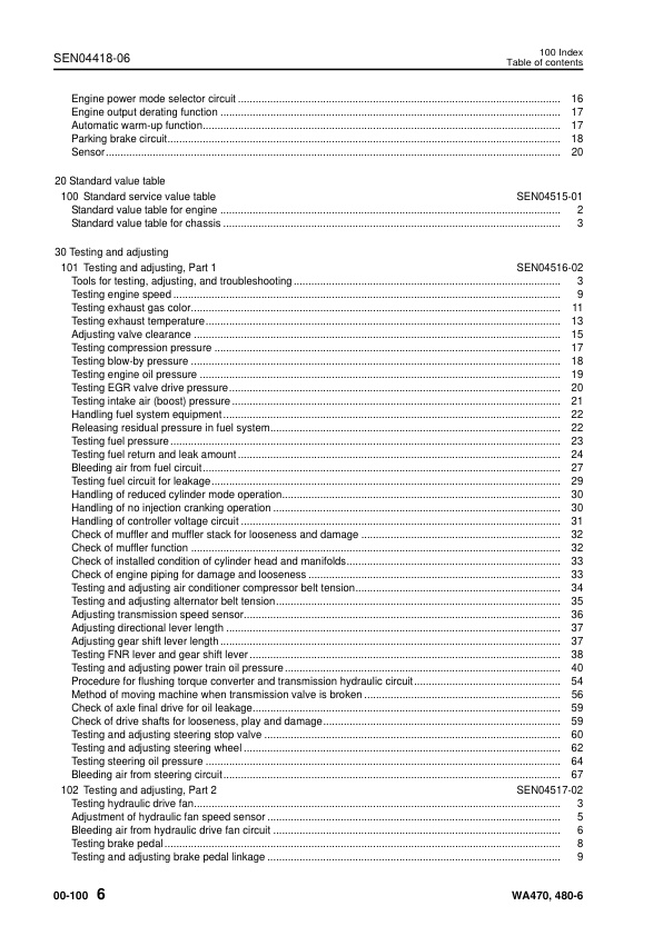
— Engine power mode selector circuit
— Engine output derating function
— Automatic warm-up function
— Parking brake circuit
— Sensor
20 Standard value table
– 100 Standard service value table
— Standard value table for engine
— Standard value table for chassis
30 Testing and adjusting
– 101 Testing and adjusting, Part 1
— Tools for testing, adjusting, and troubleshooting
— Testing engine speed
— Testing exhaust gas color
— Testing exhaust temperature
— Adjusting valve clearance
— Testing compression pressure
— Testing blow-by pressure
— Testing engine oil pressure
— Testing EGR valve drive pressure
— Testing intake air (boost) pressure
— Handling fuel system equipment
— Releasing residual pressure in fuel system
— Testing fuel pressure
— Testing fuel return and leak amount
— Bleeding air from fuel circuit
— Testing fuel circuit for leakage
— Handling of reduced cylinder mode operation
— Handling of no injection cranking operation
— Handling of controller voltage circuit
— Check of muffler and muffler stack for looseness and damage
— Check of muffler function
— Check of installed condition of cylinder head and manifolds
— Check of engine piping for damage and looseness
— Testing and adjusting air conditioner compressor belt tension
— Testing and adjusting alternator belt tension
— Adjusting transmission speed sensor
— Adjusting directional lever length
— Adjusting gear shift lever length
— Testing FNR lever and gear shift lever
— Testing and adjusting power train oil pressure
— Procedure for flushing torque converter and transmission hydraulic circuit
— Method of moving machine when transmission valve is broken
— Check of axle final drive for oil leakage
— Check of drive shafts for looseness, play and damage
— Testing and adjusting steering stop valve
— Testing and adjusting steering wheel
— Testing steering oil pressure
— Bleeding air from steering circuit
– 102 Testing and adjusting, Part 2
— Testing hydraulic drive fan
— Adjustment of hydraulic fan speed sensor
— Bleeding air from hydraulic drive fan circuit
— Testing brake pedal
— Testing and adjusting brake pedal linkage
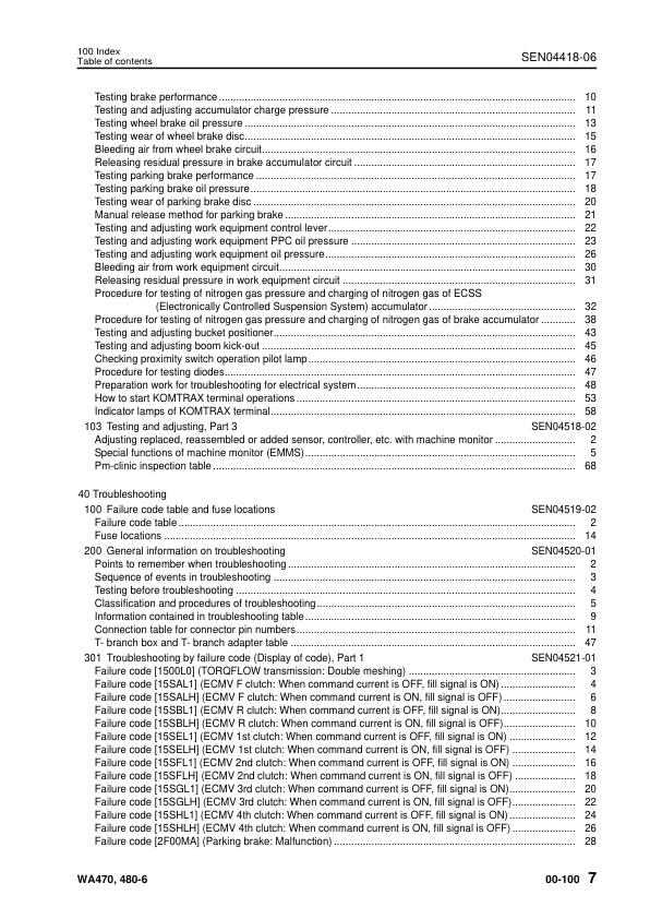
— Testing brake performance
— Testing and adjusting accumulator charge pressure
— Testing wheel brake oil pressure
— Testing wear of wheel brake disc
— Bleeding air from wheel brake circuit
— Releasing residual pressure in brake accumulator circuit
— Testing parking brake performance
— Testing parking brake oil pressure
— Testing wear of parking brake disc
— Manual release method for parking brake
— Testing and adjusting work equipment control lever
— Testing and adjusting work equipment PPC oil pressure
— Testing and adjusting work equipment oil pressure
— Bleeding air from work equipment circuit
— Releasing residual pressure in work equipment circuit
— Procedure for testing of nitrogen gas pressure and charging of nitrogen gas of ECSS (Electronically Controlled Suspension System) accumulator
— Procedure for testing of nitrogen gas pressure and charging of nitrogen gas of brake accumulator
— Testing and adjusting bucket positioner
— Testing and adjusting boom kick-out
— Checking proximity switch operation pilot lamp
— Procedure for testing diodes
— Preparation work for troubleshooting for electrical system
— How to start KOMTRAX terminal operations
— Indicator lamps of KOMTRAX terminal
– 103 Testing and adjusting, Part 3
— Adjusting replaced, reassembled or added sensor, controller, etc. with machine monitor
— Special functions of machine monitor (EMMS)
— Pm-clinic inspection table
40 Troubleshooting
– 100 Failure code table and fuse locations
— Failure code table
— Fuse locations
– 200 General information on troubleshooting
— Points to remember when troubleshooting
— Sequence of events in troubleshooting
— Testing before troubleshooting
— Classification and procedures of troubleshooting
— Information contained in troubleshooting table
— Connection table for connector pin numbers
— T- branch box and T- branch adapter table
– 301 Troubleshooting by failure code (Display of code), Part 1
— Failure code [1500L0] (TORQFLOW transmission: Double meshing)
— Failure code [15SAL1] (ECMV F clutch: When command current is OFF, fill signal is ON)
— Failure code [15SALH] (ECMV F clutch: When command current is ON, fill signal is OFF)
— Failure code [15SBL1] (ECMV R clutch: When command current is OFF, fill signal is ON)
— Failure code [15SBLH] (ECMV R clutch: When command current is ON, fill signal is OFF)
— Failure code [15SEL1] (ECMV 1st clutch: When command current is OFF, fill signal is ON)
— Failure code [15SELH] (ECMV 1st clutch: When command current is ON, fill signal is OFF)
— Failure code [15SFL1] (ECMV 2nd clutch: When command current is OFF, fill signal is ON)
— Failure code [15SFLH] (ECMV 2nd clutch: When command current is ON, fill signal is OFF)
— Failure code [15SGL1] (ECMV 3rd clutch: When command current is OFF, fill signal is ON)
— Failure code [15SGLH] (ECMV 3rd clutch: When command current is ON, fill signal is OFF)
— Failure code [15SHL1] (ECMV 4th clutch: When command current is OFF, fill signal is ON)
— Failure code [15SHLH] (ECMV 4th clutch: When command current is ON, fill signal is OFF)
— Failure code [2F00MA] (Parking brake: Malfunction)
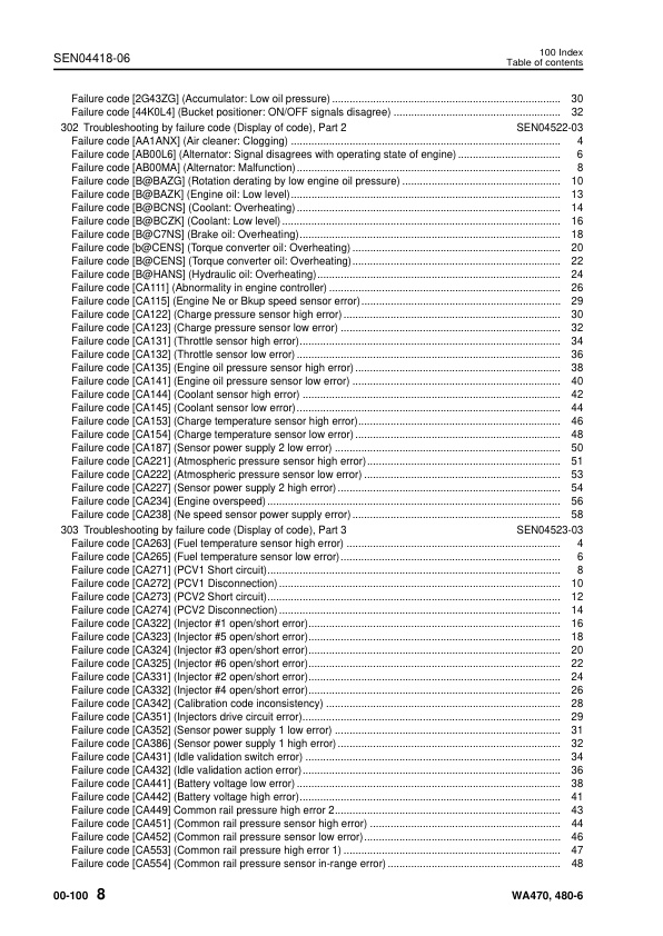
— Failure code [2G43ZG] (Accumulator: Low oil pressure)
— Failure code [44K0L4] (Bucket positioner: ON/OFF signals disagree)
– 302 Troubleshooting by failure code (Display of code), Part 2
— Failure code [AA1ANX] (Air cleaner: Clogging)
— Failure code [AB00L6] (Alternator: Signal disagrees with operating state of engine)
— Failure code [AB00MA] (Alternator: Malfunction)
— Failure code [B@BAZG] (Rotation derating by low engine oil pressure)
— Failure code [B@BAZK] (Engine oil: Low level)
— Failure code [B@BCNS] (Coolant: Overheating)
— Failure code [B@BCZK] (Coolant: Low level)
— Failure code [B@C7NS] (Brake oil: Overheating)
— Failure code [b@CENS] (Torque converter oil: Overheating)
— Failure code [B@CENS] (Torque converter oil: Overheating)
— Failure code [B@HANS] (Hydraulic oil: Overheating)
— Failure code [CA111] (Abnormality in engine controller)
— Failure code [CA115] (Engine Ne or Bkup speed sensor error)
— Failure code [CA122] (Charge pressure sensor high error)
— Failure code [CA123] (Charge pressure sensor low error)
— Failure code [CA131] (Throttle sensor high error)
— Failure code [CA132] (Throttle sensor low error)
— Failure code [CA135] (Engine oil pressure sensor high error)
— Failure code [CA141] (Engine oil pressure sensor low error)
— Failure code [CA144] (Coolant sensor high error)
— Failure code [CA145] (Coolant sensor low error)
— Failure code [CA153] (Charge temperature sensor high error)
— Failure code [CA154] (Charge temperature sensor low error)
— Failure code [CA187] (Sensor power supply 2 low error)
— Failure code [CA221] (Atmospheric pressure sensor high error)
— Failure code [CA222] (Atmospheric pressure sensor low error)
— Failure code [CA227] (Sensor power supply 2 high error)
— Failure code [CA234] (Engine overspeed)
— Failure code [CA238] (Ne speed sensor power supply error)
– 303 Troubleshooting by failure code (Display of code), Part 3
— Failure code [CA263] (Fuel temperature sensor high error)
— Failure code [CA265] (Fuel temperature sensor low error)
— Failure code [CA271] (PCV1 Short circuit)
— Failure code [CA272] (PCV1 Disconnection)
— Failure code [CA273] (PCV2 Short circuit)
— Failure code [CA274] (PCV2 Disconnection)
— Failure code [CA322] (Injector #1 open/short error)
— Failure code [CA323] (Injector #5 open/short error)
— Failure code [CA324] (Injector #3 open/short error)
— Failure code [CA325] (Injector #6 open/short error)
— Failure code [CA331] (Injector #2 open/short error)
— Failure code [CA332] (Injector #4 open/short error)
— Failure code [CA342] (Calibration code inconsistency)
— Failure code [CA351] (Injectors drive circuit error)
— Failure code [CA352] (Sensor power supply 1 low error)
— Failure code [CA386] (Sensor power supply 1 high error)
— Failure code [CA431] (Idle validation switch error)
— Failure code [CA432] (Idle validation action error)
— Failure code [CA441] (Battery voltage low error)
— Failure code [CA442] (Battery voltage high error)
— Failure code [CA449] Common rail pressure high error 2
— Failure code [CA451] (Common rail pressure sensor high error)
— Failure code [CA452] (Common rail pressure sensor low error)
— Failure code [CA553] (Common rail pressure high error 1)
— Failure code [CA554] (Common rail pressure sensor in-range error)
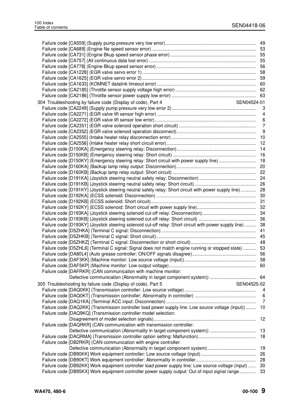
— Failure code [CA559] (Supply pump pressure very low error)
— Failure code [CA689] (Engine Ne speed sensor error)
— Failure code [CA731] (Engine Bkup speed sensor phase error)
— Failure code [CA757] (All continuous data lost error)
— Failure code [CA778] (Engine Bkup speed sensor error)
— Failure code [CA1228] (EGR valve servo error 1)
— Failure code [CA1625] (EGR valve servo error 2)
— Failure code [CA1633] (KOMNET datalink timeout error)
— Failure code [CA2185] (Throttle sensor supply voltage high error)
— Failure code [CA2186] (Throttle sensor power supply low error)
– 304 Troubleshooting by failure code (Display of code), Part 4
— Failure code [CA2249] (Supply pump pressure very low error 2)
— Failure code [CA2271] (EGR valve lift sensor high error)
— Failure code [CA2272] (EGR valve lift sensor low error)
— Failure code [CA2351] (EGR valve solenoid operation short circuit)
— Failure code [CA2352] (EGR valve solenoid operation disconnect)
— Failure code [CA2555] (Intake heater relay disconnection error)
— Failure code [CA2556] (Intake heater relay short circuit error)
— Failure code [D150KA] (Emergency steering relay: Disconnection)
— Failure code [D150KB] (Emergency steering relay: Short circuit)
— Failure code [D150KY] (Emergency steering relay: Short circuit with power supply line)
— Failure code [D160KA] (Backup lamp relay output: Disconnection)
— Failure code [D160KB] (Backup lamp relay output: Short circuit)
— Failure code [D191KA] (Joystick steering neutral safety relay: Disconnection)
— Failure code [D191KB] (Joystick steering neutral safety relay: Short circuit)
— Failure code [D191KY] (Joystick steering neutral safety relay: Short circuit with power supply line)
— Failure code [D192KA] (ECSS solenoid: Disconnection)
— Failure code [D192KB] (ECSS solenoid: Short circuit)
— Failure code [D192KY] (ECSS solenoid: Short circuit with power supply line)
— Failure code [D193KA] (Joystick steering solenoid cut-off relay: Disconnection)
— Failure code [D193KB] (Joystick steering solenoid cut-off relay: Short circuit)
— Failure code [D193KY] (Joystick steering solenoid cut-off relay: Short circuit with power supply line)
— Failure code [D5ZHKA] (Terminal C signal: Disconnection)
— Failure code [D5ZHKB] (Terminal C signal: Short circuit)
— Failure code [D5ZHKZ] (Terminal C signal: Disconnection or short circuit)
— Failure code [D5ZHL6] (Terminal C signal: Signal does not match engine running or stopped state)
— Failure code [DA80L4] (Auto grease controller: ON/OFF signals disagree)
— Failure code [DAF3KK] (Machine monitor: Low source voltage (input))
— Failure code [DAF5KP] (Machine monitor: Low output voltage)
— Failure code [DAFRKR] (CAN communication with machine monitor: Defective communication (Abnormality in target component system))
– 305 Troubleshooting by failure code (Display of code), Part 5
— Failure code [DAQ0KK] (Transmission controller: Low source voltage)
— Failure code [DAQ0KT] (Transmission controller: Abnormality in controller)
— Failure code [DAQ1KA] (Terminal ACC input: Disconnection)
— Failure code [DAQ2KK] (Transmission controller load power supply line: Low source voltage (input))
— Failure code [DAQ9KQ] (Transmission controller model selection: Disagreement of model selection signals)
— Failure code [DAQRKR] (CAN communication with transmission controller: Defective communication (Abnormality in target component system))
— Failure code [DAQRMA] (Transmission controller option setting: Malfunction)
— Failure code [DB2RKR] (CAN communication with engine controller: Defective communication (Abnormality in target component system)
— Failure code [DB90KK] Work equipment controller: Low source voltage (input)
— Failure code [DB90KT] Work equipment controller: Abnormality in controller
— Failure code [DB92KK] Work equipment controller load power supply line: Low source voltage (input)
— Failure code [DB95KX] Work equipment controller power supply output: Out of input signal range
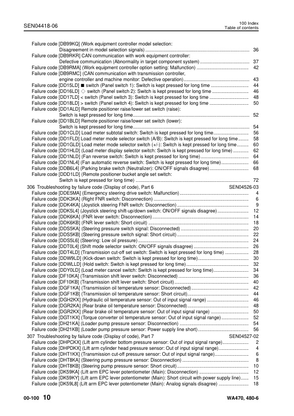
— Failure code [DB99KQ] (Work equipment controller model selection: Disagreement in model selection signals)
— Failure code [DB9RKR] CAN communication with work equipment controller: Defective communication (Abnormality in target component system)
— Failure code [DB9RMA] (Work equipment controller option setting: Malfunction)
— Failure code [DB9RMC] (CAN communication with transmission controller, engine controller and machine monitor: Defective operation)
— Failure code [DD15LD] ■ switch (Panel switch 1): Switch is kept pressed for long time
— Failure code [DD16LD] ◇ switch (Panel switch 2): Switch is kept pressed for long time
— Failure code [DD17LD] < switch (Panel switch 3): Switch is kept pressed for long time
-- Failure code [DD18LD] > switch (Panel switch 4): Switch is kept pressed for long time
— Failure code [DD1ALD] Remote positioner raise/lower set switch (raise): Switch is kept pressed for long time
— Failure code [DD1BLD] Remote positioner raise/lower set switch (lower): Switch is kept pressed for long time
— Failure code [DD1CLD] Load meter subtotal switch: Switch is kept pressed for long time
— Failure code [DD1FLD] Load meter mode selector switch (A/B): Switch is kept pressed for long time
— Failure code [DD1GLD] Load meter mode selector switch (+/–): Switch is kept pressed for long time
— Failure code [DD1HLD] (Load meter display selector switch: Switch is kept pressed for long time)
— Failure code [DD1NLD] (Fan reverse switch: Switch is kept pressed for long time)
— Failure code [DD1NL4] (Fan automatic reverse switch: Switch is kept pressed for long time)
— Failure code [DDB6L4] (Parking brake switch (Neutralizer): ON/OFF signals disagree)
— Failure code [DDD1LD] (Remote positioner bucket angle set switch: Switch is kept pressed for long time)
– 306 Troubleshooting by failure code (Display of code), Part 6
— Failure code [DDE5MA] (Emergency steering drive switch: Malfunction)
— Failure code [DDK3KA] (Right FNR switch: Disconnection)
— Failure code [DDK4KA] (Joystick steering FNR switch: Disconnection)
— Failure code [DDK5L4] (Joystick steering shift-up/down switch: ON/OFF signals disagree)
— Failure code [DDK6KA] (FNR lever switch: Disconnection)
— Failure code [DDK6KB] (FNR lever switch: Short circuit)
— Failure code [DDS5KA] (Steering pressure switch signal: Disconnected)
— Failure code [DDS5KB] (Steering pressure switch signal: Short circuit)
— Failure code [DDS5L6] (Steering: Low oil pressure)
— Failure code [DDT0L4] (Shift mode selector switch: ON/OFF signals disagree)
— Failure code [DDT4LD] (Transmission cut-off set switch: Switch is kept pressed for long time)
— Failure code [DDW9LD] (Kick-down switch: Switch is kept pressed for long time)
— Failure code [DDWLLD] (Hold switch: Switch is kept pressed for long time)
— Failure code [DDY0LD] (Load meter cancel switch: Switch is kept pressed for long time)
— Failure code [DF10KA] (Transmission shift lever switch: Disconnected)
— Failure code [DF10KB] (Transmission shift lever switch: Short circuit)
— Failure code [DGF1KA] (Transmission oil temperature sensor: Disconnected)
— Failure code [DGF1KB] (Transmission oil temperature sensor: Short circuit)
— Failure code [DGH2KX] (Hydraulic oil temperature sensor: Out of input signal range)
— Failure code [DGR2KA] (Rear brake oil temperature sensor: Disconnected)
— Failure code [DGR2KX] (Rear brake oil temperature sensor: Out of input signal range)
— Failure code [DGT1KX] (Torque converter oil temperature sensor: Out of input signal range)
— Failure code [DH21KA] (Loader pump pressure sensor: Disconnection)
— Failure code [DH21KB] (Loader pump pressure sensor: Power supply line short)
– 307 Troubleshooting by failure code (Display of code), Part 7
— Failure code [DHPCKX] (Lift arm cylinder bottom pressure sensor: Out of input signal range)
— Failure code [DHPDKX] (Lift arm cylinder head pressure sensor: Out of input signal range)
— Failure code [DHT1KX] (Transmission cut-off pressure sensor: Out of input signal range)
— Failure code [DHT8KA] (Steering pump pressure sensor: Disconnection)
— Failure code [DHT8KB] (Steering pump pressure sensor: Short circuit)
— Failure code [DK59KA] (Lift arm EPC lever potentiometer (Main): Disconnection)
— Failure code [DK59KY] (Lift arm EPC lever potentiometer (Main): Short circuit with power supply line)
— Failure code [DK59L8] (Lift arm EPC lever potentiometer (Main): Analog signals disagree)
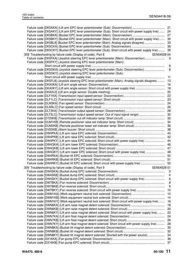
— Failure code [DK5AKA] (Lift arm EPC lever potentiometer (Sub): Disconnection)
— Failure code [DK5AKY] (Lift arm EPC lever potentiometer (Sub): Short circuit with power supply line)
— Failure code [DK5BKA] (Bucket EPC lever potentiometer (Main): Disconnection)
— Failure code [DK5BKY] (Bucket EPC lever potentiometer (Main): Short circuit with power supply line)
— Failure code [DK5BL8] (Bucket EPC lever potentiometer (Main): Analog signals disagree)
— Failure code [DK5CKA] (Bucket EPC lever potentiometer (Sub): Disconnection)
— Failure code [DK5CKY] (Bucket EPC lever potentiometer (Sub): Short circuit with power supply line)
– 308 Troubleshooting by failure code (Display of code), Part 8
— Failure code [DK5FKA] (Joystick steering EPC lever potentiometer (Main): Disconnection)
— Failure code [DK5FKY] (Joystick steering EPC lever potentiometer (Main): Short circuit with power supply line)
— Failure code [DK5GKA] (Joystick steering EPC lever potentiometer (Sub): Disconnection)
— Failure code [DK5GKY] (Joystick steering EPC lever potentiometer (Sub): Short circuit with power supply line)
— Failure code [DK5FL8] (Joystick steering EPC lever potentiometer (Main): Analog signals disagree)
— Failure code [DKA0KA] (Lift arm angle sensor: Disconnection)
— Failure code [DKA0KY] (Lift arm angle sensor: Short circuit with power supply line)
— Failure code [DKA0L0] (Lift arm angle sensor: Double meshing)
— Failure code [DLF1KA] (Transmission input speed sensor: Disconnection)
— Failure code [DLF1LC] (Transmission input speed sensor: Short circuit)
— Failure code [DLM3KA] (Fan speed sensor: Disconnection)
— Failure code [DLM3LC] (Fan speed sensor: Short circuit)
— Failure code [DLT3KA] (Transmission output speed sensor: Disconnection)
— Failure code [DLT3LC] (Transmission output speed sensor: Out of input signal range)
— Failure code [DT20KB] (Transmission cut-off indicator lamp: Short circuit)
— Failure code [DUM1KB] (Remote positioner raise set indicator lamp: Short circuit)
— Failure code [DUM2KB] (Remote positioner lower set indicator lamp: Short circuit)
— Failure code [DV00KB] (Alarm buzzer: Short circuit)
— Failure code [DW4PKA] (Lift arm raise EPC solenoid: Disconnection)
— Failure code [DW4PKB] (Lift arm raise EPC solenoid: Short circuit)
— Failure code [DW4PKY] (Lift arm raise EPC solenoid: Short circuit with power supply line)
— Failure code [DW4QKA] (Lift arm lower EPC solenoid: Disconnection)
— Failure code [DW4QKB] (Lift arm lower EPC solenoid: Short circuit)
— Failure code [DW4QKY] (Lift arm lower EPC solenoid: Short circuit with power supply line)
— Failure code [DW4RKA] (Bucket tilt EPC solenoid: Disconnection)
— Failure code [DW4RKB] (Bucket tilt EPC solenoid: Short circuit)
— Failure code [DW4RKY] (Bucket tilt EPC solenoid: Short circuit with power supply line)
– 309 Troubleshooting by failure code (Display of code), Part 9
— Failure code [DW4SKA] (Bucket dump EPC solenoid: Disconnection)
— Failure code [DW4SKB] (Bucket dump EPC solenoid: Short circuit)
— Failure code [DW4SKY] (Bucket dump EPC solenoid: Short circuit with power supply line)
— Failure code [DW7BKA] (Fan reverse solenoid: Disconnection)
— Failure code [DW7BKB] (Fan reverse solenoid: Short circuit)
— Failure code [DW7BKY] (Fan reverse solenoid: Short circuit with power supply line)
— Failure code [DWM1KA] (Work equipment neutral lock solenoid: Disconnection)
— Failure code [DWM1KB] (Work equipment neutral lock solenoid: Short circuit)
— Failure code [DWM1KY] (Work equipment neutral lock solenoid: Short circuit with power supply line)
— Failure code [DWN6KA] (Lift arm raise magnet detent solenoid: Disconnection)
— Failure code [DWN6KB] (Lift arm raise magnet detent solenoid: Short circuit)
— Failure code [DWN6KY] (Lift arm raise magnet detent solenoid: Short circuit with power supply line)
— Failure code [DWN7KA] (Lift arm float magnet detent solenoid: Disconnection)
— Failure code [DWN7KB] (Lift arm float magnet detent solenoid: Short circuit)
— Failure code [DWN7KY] (Lift arm float magnet detent solenoid: Short circuit with power supply line)
— Failure code [DWN8KA] (Bucket tilt magnet detent solenoid: Disconnection)
— Failure code [DWN8KB] (Bucket tilt magnet detent solenoid: Short circuit)
— Failure code [DWN8KY] (Bucket tilt magnet detent solenoid: Shorted with the power source)
— Failure code [DX16KA] (Fan pump EPC solenoid: Disconnection)
— Failure code [DX16KB] (Fan pump EPC solenoid: Short circuit)
— Failure code [DX16KY] (Fan pump EPC solenoid: Short circuit with power supply line)
— Failure code [DXA1KA] (Loader pump PC-EPC solenoid: Disconnection)
— Failure code [DXA1KB] (Loader pump PC-EPC solenoid: Short circuit)
— Failure code [DXANKA] (Steering pump PC-EPC solenoid: Disconnection)
— Failure code [DXANKB] (Steering pump PC-EPC solenoid: Short circuit)
— Failure code [DXH1KA] (Lockup ECMV solenoid: Disconnection)
— Failure code [DXH1KB] (Lockup ECMV solenoid: Short circuit)
— Failure code [DXH1KY] (Lockup ECMV solenoid: Short circuit with power supply line)
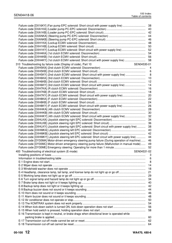
— Failure code [DXH4KA] (1st clutch ECMV solenoid: Disconnection)
— Failure code [DXH4KB] (1st clutch ECMV solenoid: Short circuit)
— Failure code [DXH4KY] (1st clutch ECMV solenoid: Short circuit with power supply line)
– 310 Troubleshooting by failure code (Display of code), Part 10
— Failure code [DXH5KA] (2nd clutch ECMV solenoid: Disconnection)
— Failure code [DXH5KB] (2nd clutch ECMV solenoid: Short circuit)
— Failure code [DXH5KY] (2nd clutch ECMV solenoid: Short circuit with power supply line)
— Failure code [DXH6KA] (3rd clutch ECMV solenoid: Disconnection)
— Failure code [DXH6KB] (3rd clutch ECMV solenoid: Short circuit)
— Failure code [DXH6KY] (3rd clutch ECMV solenoid: Short circuit with power supply line)
— Failure code [DXH7KA] (R clutch ECMV solenoid: Disconnection)
— Failure code [DXH7KB] (R clutch ECMV solenoid: Short circuit)
— Failure code [DXH7KY] (R clutch ECMV solenoid: Short circuit with power supply line)
— Failure code [DXH8KA] (F clutch ECMV solenoid: Disconnection)
— Failure code [DXH8KB] (F clutch ECMV solenoid: Short circuit)
— Failure code [DXH8KY] (F clutch ECMV solenoid: Short circuit with power supply line)
— Failure code [DXHHKA] (4th clutch ECMV solenoid: Disconnection)
— Failure code [DXHHKB] (4th clutch ECMV solenoid: Short circuit)
— Failure code [DXHHKY] (4th clutch ECMV solenoid: Short circuit with power supply line)
— Failure code [DXHLKA] (Joystick steering right EPC solenoid: Disconnection)
— Failure code [DXHLKB] (Joystick steering right EPC solenoid: Short circuit)
— Failure code [DXHLKY] (Joystick steering right EPC solenoid: Short circuit with power supply line)
— Failure code [DXHMKA] (Joystick steering left EPC solenoid: Disconnection)
— Failure code [DXHMKB] (Joystick steering left EPC solenoid: Short circuit)
— Failure code [DXHMKY] (Joystick steering left EPC solenoid: Short circuit with power supply line)
— Failure code [DY30MA] Motor-driven emergency steering pump failure (During operation of machine)
— Failure code [DY30MC] Motor-driven emergency steering pump failure (Malfunction in manual mode)
— Failure code [DY30ME] Emergency steering: Operating for more than 1 minute
– 400 Troubleshooting of electrical system (E-mode)
— Installing positions of fuses
— Information in troubleshooting table
— E-1 Engine does not start
— E-2 Wiper does not operate
— E-3 Windshield washer does not operate
— E-4 Headlamp, clearance lamp, tail lamp, and license lamp do not light up or go off
— E-5 Working lamp does not light up or go off
— E-6 Turn signal lamp and hazard lamp do not light up or go off
— E-7 Brake lamp does not light or it keeps lighting up
— E-8 Backup lamp does not light or it keeps lighting up
— E-9 Backup buzzer does not sound or it keeps sounding
— E-10 Horn does not sound or it keeps sounding
— E-11 Alarm buzzer does not sound or it keeps sounding
— E-12 Air conditioner does not operate or stop
— E-13 The KOMTRAX system does not work properly
— E-14 When kick-down switch is turned ON, kick-down operation does not start
— E-15 When hold switch is pressed, holding operation does not start
— E-16 Transmission is kept in neutral, or brake drags when directional lever is operated while parking brake is applied
— E-17 Transmission cut-off mode cannot be set or reset
— E-18 Transmission cut-off set cannot be reset
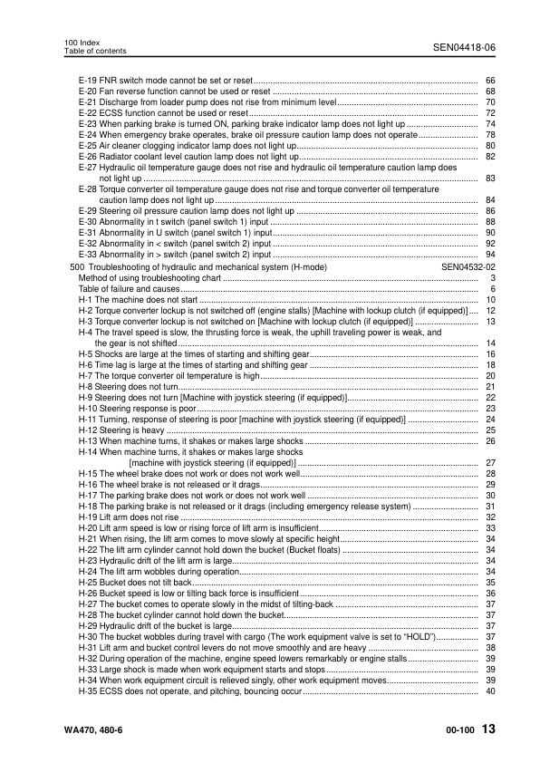
— E-19 FNR switch mode cannot be set or reset
— E-20 Fan reverse function cannot be used or reset
— E-21 Discharge from loader pump does not rise from minimum level
— E-22 ECSS function cannot be used or reset
— E-23 When parking brake is turned ON, parking brake indicator lamp does not light up
— E-24 When emergency brake operates, brake oil pressure caution lamp does not operate
— E-25 Air cleaner clogging indicator lamp does not light up
— E-26 Radiator coolant level caution lamp does not light up
— E-27 Hydraulic oil temperature gauge does not rise and hydraulic oil temperature caution lamp does not light up
— E-28 Torque converter oil temperature gauge does not rise and torque converter oil temperature caution lamp does not light up
— E-29 Steering oil pressure caution lamp does not light up
— E-30 Abnormality in ■ switch (panel switch 1) input
— E-31 Abnormality in ◇ switch (panel switch 1) input
— E-32 Abnormality in < switch (panel switch 2) input
-- E-33 Abnormality in > switch (panel switch 2) input
– 500 Troubleshooting of hydraulic and mechanical system (H-mode)
— Method of using troubleshooting chart
— Table of failure and causes
— H-1 The machine does not start
— H-2 Torque converter lockup is not switched off (engine stalls) [Machine with lockup clutch (if equipped)]
— H-3 Torque converter lockup is not switched on [Machine with lockup clutch (if equipped)]
— H-4 The travel speed is slow, the thrusting force is weak, the uphill traveling power is weak, and the gear is not shifted
— H-5 Shocks are large at the times of starting and shifting gear
— H-6 Time lag is large at the times of starting and shifting gear
— H-7 The torque converter oil temperature is high
— H-8 Steering does not turn
— H-9 Steering does not turn [Machine with joystick steering (if equipped)]
— H-10 Steering response is poor
— H-11 Turning, response of steering is poor [machine with joystick steering (if equipped)]
— H-12 Steering is heavy
— H-13 When machine turns, it shakes or makes large shocks
— H-14 When machine turns, it shakes or makes large shocks [machine with joystick steering (if equipped)]
— H-15 The wheel brake does not work or does not work well
— H-16 The wheel brake is not released or it drags
— H-17 The parking brake does not work or does not work well
— H-18 The parking brake is not released or it drags (including emergency release system)
— H-19 Lift arm does not rise
— H-20 Lift arm speed is low or rising force of lift arm is insufficient
— H-21 When rising, the lift arm comes to move slowly at specific height
— H-22 The lift arm cylinder cannot hold down the bucket (Bucket floats)
— H-23 Hydraulic drifts of the lift arm is large
— H-24 The lift arm wobbles during operation
— H-25 Bucket does not tilt back
— H-26 Bucket speed is low or tilting back force is insufficient
— H-27 The bucket comes to operate slowly in the midst of tilting-back
— H-28 The bucket cylinder cannot hold down the bucket
— H-29 Hydraulic drifts of the bucket is large
— H-30 The bucket wobbles during travel with cargo (The work equipment valve is set to “HOLD”)
— H-31 Lift arm and bucket control levers do not move smoothly and are heavy
— H-32 During operation of the machine, engine speed lowers remarkably or engine stalls
— H-33 Large shock is made when work equipment starts and stops
— H-34 When work equipment circuit is relieved singly, other work equipment moves
— H-35 ECSS does not operate, and pitching, bouncing occur
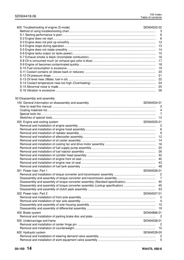
– 600 Troubleshooting of engine (S-mode)
— Method of using troubleshooting chart
— S-1 Starting performance is poor.
— S-2 Engine does not start
— S-3 Engine does not pick up smoothly
— S-4 Engine stops during operation
— S-5 Engine does not rotate smoothly
— S-6 Engine lacks output (or lacks power)
— S-7 Exhaust smoke is black (Incomplete combustion)
— S-8 Oil is consumed much (or exhaust gas color is blue)
— S-9 Engine oil becomes contaminated quickly
— S-10 Fuel consumption is excessive
— S-11 Coolant contains oil (blows back or reduces)
— S-12 Oil pressure drops
— S-13 Oil level rises (Water, fuel in oil)
— S-14 Coolant temperature rises too high (Overheating)
— S-15 Abnormal noise is made
— S-16 Vibration is excessive
50 Disassembly and assembly
– 100 General information on disassembly and assembly
— How to read this manual
— Coating materials list
— Special tools list
— Sketches of special tools
– 200 Engine and cooling system
— Removal and installation of engine assembly
— Removal and installation of engine hood assembly
— Removal and installation of radiator assembly
— Removal and installation of aftercooler assembly
— Removal and installation of oil cooler assembly
— Removal and installation of cooling fan and drive motor assembly
— Removal and installation of fuel supply pump assembly
— Removal and installation of fuel injector assembly
— Removal and installation of cylinder head assembly
— Removal and installation of engine front oil seal
— Removal and Installation of engine rear oil seal
— Removal and installation of fuel tank assembly
– 301 Power train, Part 1
— Removal and installation of torque converter and transmission assembly
— Disassembly and assembly of torque converter and transmission assembly
— Disassembly and assembly of torque converter assembly (Standard specification)
— Disassembly and assembly of torque converter assembly (Lockup specification)
— Disassembly and assembly of clutch pack assembly
– 302 Power train, Part 2
— Removal and installation of front axle assembly
— Removal and installation of rear axle assembly
— Disassembly and assembly of axle housing assembly
— Disassembly and assembly of differential assembly
– 400 Brake system
— Removal and installation of parking brake disc and plate
– 500 Undercarriage and frame
— Removal and installation of center hinge pin
— Removal and installation of counterweight
– 600 Hydraulic system
— Removal and installation of steering demand valve assembly
— Removal and installation of work equipment valve assembly
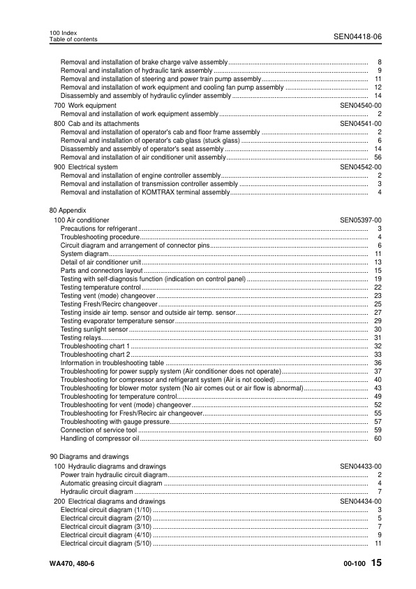
— Removal and installation of brake charge valve assembly
— Removal and installation of hydraulic tank assembly
— Removal and installation of steering and power train pump assembly
— Removal and installation of work equipment and cooling fan pump assembly
— Disassembly and assembly of hydraulic cylinder assembly
– 700 Work equipment
— Removal and installation of work equipment assembly
– 800 Cab and its attachments
— Removal and installation of operator’s cab and floor frame assembly
— Removal and installation of operator’s cab glass (stuck glass)
— Disassembly and assembly of operator’s seat assembly
— Removal and installation of air conditioner unit assembly
– 900 Electrical system
— Removal and installation of engine controller assembly
— Removal and installation of transmission controller assembly
— Removal and installation of KOMTRAX terminal assembly
80 Appendix
– 100 Air conditioner
— Precautions for refrigerant
— Troubleshooting procedure
— Circuit diagram and arrangement of connector pins
— System diagram
— Detail of air conditioner unit
— Parts and connectors layout
— Testing with self-diagnosis function (indication on control panel)
— Testing temperature control
— Testing vent (mode) changeover
— Testing Fresh/Recirc changeover
— Testing inside air temp. sensor and outside air temp. sensor
— Testing evaporator temperature sensor
— Testing sunlight sensor
— Testing relays
— Troubleshooting chart 1
— Troubleshooting chart 2
— Information in troubleshooting table
— Troubleshooting for power supply system (Air conditioner does not operate)
— Troubleshooting for compressor and refrigerant system (Air is not cooled)
— Troubleshooting for blower motor system (No air comes out or air flow is abnormal)
— Troubleshooting for temperature control
— Troubleshooting for vent (mode) changeover
— Troubleshooting for Fresh/Recirc air changeover
— Troubleshooting with gauge pressure
— Connection of service tool
— Handling of compressor oil
90 Diagrams and drawings
– 100 Hydraulic diagrams and drawings
— Power train hydraulic circuit diagram
— Automatic greasing circuit diagram
— Hydraulic circuit diagram
– 200 Electrical diagrams and drawings
— Electrical circuit diagram (1/10)
— Electrical circuit diagram (2/10)
— Electrical circuit diagram (3/10)
— Electrical circuit diagram (4/10)
— Electrical circuit diagram (5/10)
— Electrical circuit diagram (6/10)
— Electrical circuit diagram (7/10)
— Electrical circuit diagram (8/10)
— Electrical circuit diagram (9/10)
— Electrical circuit diagram (10/10)
— Work equipment controller system electrical circuit diagram
— Connector list and stereogram
Reviews
There are no reviews yet.