Komatsu WA800-3E0 70001 & Up, WA900-3E0 60001 & Up SEN02034-09 (Preview)
COVER
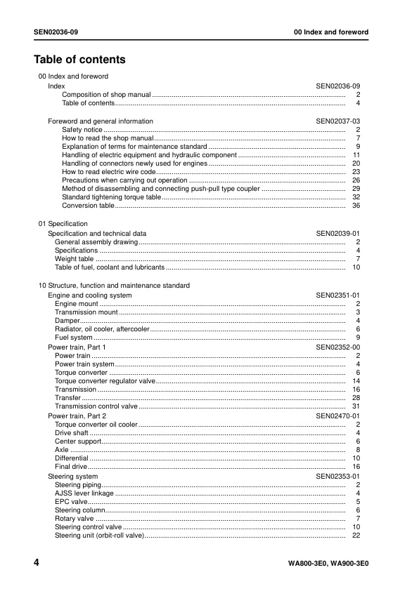
00 Index and foreword
– Index
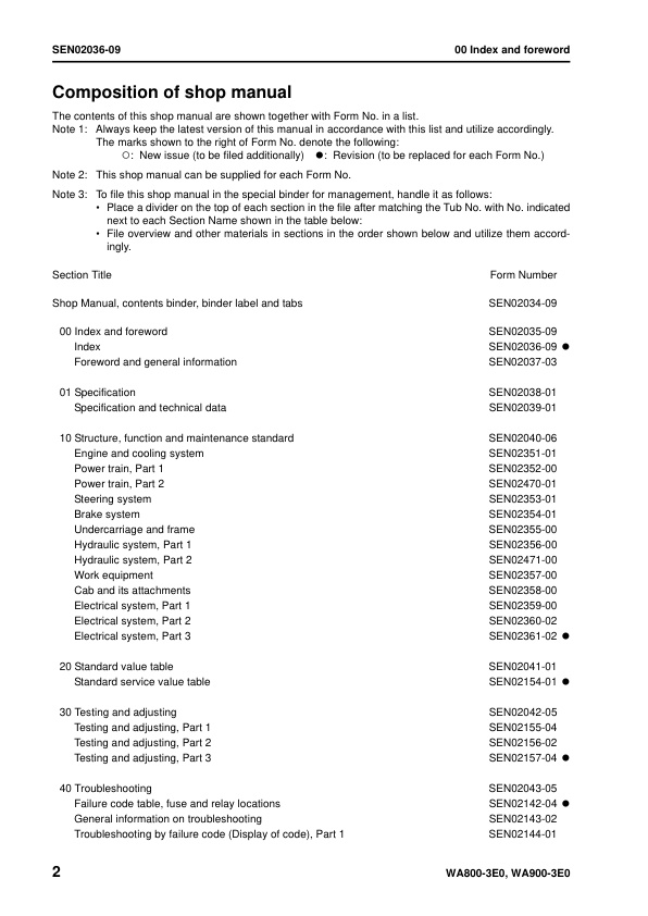
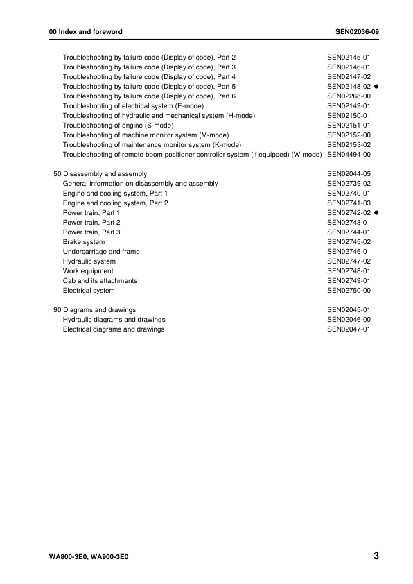
— Composition of shop manual
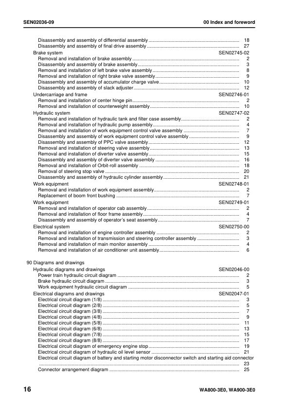
— Table of contents
– Foreword and general information
— Safety notice
— How to read the shop manual
— Explanation of terms for maintenance standard
— Handling of electric equipment and hydraulic component
— Handling of connectors newly used for engines
— How to read electric wire code
— Precautions when carrying out operation
— Method of disassembling and connecting push-pull type coupler
— Standard tightening torque table
— Conversion table
01 Specification
– Specification and technical data
— General assembly drawing
— Specifications
— Weight table
— Table of fuel, coolant and lubricants
10 Structure, function and maintenance standard
– Engine and cooling system
— Engine mount
— Transmission mount
— Damper
— Radiator, oil cooler, aftercooler
— Fuel system
– Power train, Part 1
— Power train
— Power train system
— Torque converter
— Torque converter regulator valve
— Transmission
— Transfer
— Transmission control valve
– Power train, Part 2
— Torque converter oil cooler
— Drive shaft
— Center support
— Axle
— Differential
— Final drive
– Steering system
— Steering piping
— AJSS lever linkage
— EPC valve
— Steering column
— Rotary valve
— Steering control valve
— Steering unit (orbit-roll valve)
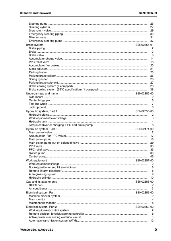
— Steering pump
— Steering cylinder
— Slow return valve
— Emergency steering piping
— Diverter valve
— Emergency steering pump
– Brake system
— Brake piping
— Brake
— Brake valve
— Accumulator charge valve
— PPC relief valve
— Accumulator (for brake)
— Slack adjuster
— Parking brake
— Parking brake caliper
— Spring cylinder
— Parking brake solenoid
— Brake cooling system (if equipped)
— Brake cooling system (55°C specification) (If equipped)
– Undercarriage and frame
— Axle mount
— Center hinge pin
— Tire and wheel
— Jack up point
– Hydraulic system, Part 1
— Hydraulic piping
— Work equipment lever linkage
— Hydraulic tank
— Torque conbverter charging, PPC and brake pump
– Hydraulic system, Part 2
— Main control valve
— Accumulator (For PPC valve)
— Main piston pump
— Main piston pump cut-off solenoid valve
— PPC valve
— PPC relief valve
— Switch pump
— Control pump
– Work equipment
— Work equipment linkage
— Bucket positioner and lift arm kick-out
— Remote lift arm positioner
— Auto greasing system
— Hydraulic cylinder
– Cab and its attachments
— ROPS cab
— Air conditioner
– Electrical system, Part 1
— Machine monitor system
— Main monitor
— Maintenance monitor
– Electrical system, Part 2
— Work equipment control system
— Remote position, joystick steering controller
— Active power maximizing electrical circuit
— Automatic transmission system (ATM)
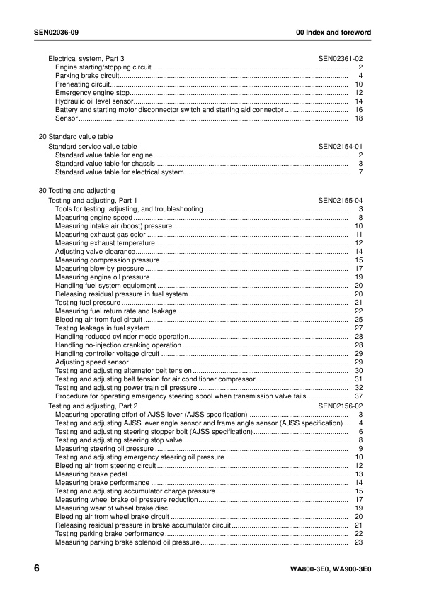
– Electrical system, Part 3
— Engine starting/stopping circuit
— Parking brake circuit
— Preheating circuit
— Emergency engine stop
— Hydraulic oil level sensor
— Battery and starting motor disconnector switch and starting aid connector
— Sensor
20 Standard value table
– Standard service value table
— Standard value table for engine
— Standard value table for chassis
— Standard value table for electrical system
30 Testing and adjusting
– Testing and adjusting, Part 1
— Tools for testing, adjusting, and troubleshooting
— Measuring engine speed
— Measuring intake air (boost) pressure
— Measuring exhaust gas color
— Measuring exhaust temperature
— Adjusting valve clearance
— Measuring compression pressure
— Measuring blow-by pressure
— Measuring engine oil pressure
— Handling fuel system equipment
— Releasing residual pressure in fuel system
— Testing fuel pressure
— Measuring fuel return rate and leakage
— Bleeding air from fuel circuit
— Testing leakage in fuel system
— Handling reduced cylinder mode operation
— Handling no-injection cranking operation
— Handling controller voltage circuit
— Adjusting speed sensor
— Testing and adjusting alternator belt tension
— Testing and adjusting belt tension for air conditioner compressor
— Testing and adjusting power train oil pressure
— Procedure for operating emergency steering spool when transmission valve fails
– Testing and adjusting, Part 2
— Measuring operating effort of AJSS lever (AJSS specification)
— Testing and adjusting AJSS lever angle sensor and frame angle sensor (AJSS specification)
— Testing and adjusting steering stopper bolt (AJSS specification)
— Testing and adjusting steering stop valve
— Measuring steering oil pressure
— Testing and adjusting emergency steering oil pressure
— Bleeding air from steering circuit
— Measuring brake pedal
— Measuring brake performance
— Testing and adjusting accumulator charge pressure
— Measuring wheel brake oil pressure reduction
— Measuring wear of wheel brake disc
— Bleeding air from wheel brake circuit
— Releasing residual pressure in brake accumulator circuit
— Testing parking brake performance
— Measuring parking brake solenoid oil pressure
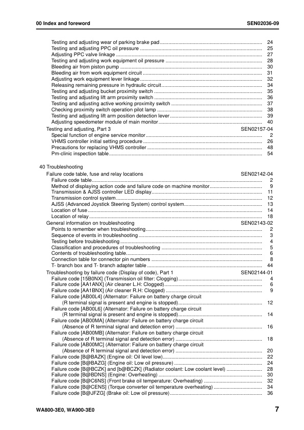
— Testing and adjusting wear of parking brake pad
— Testing and adjusting PPC oil pressure
— Adjusting PPC valve linkage
— Testing and adjusting work equipment oil pressure
— Bleeding air from piston pump
— Bleeding air from work equipment circuit
— Adjusting work equipment lever linkage
— Releasing remaining pressure in hydraulic circuit
— Testing and adjusting bucket proximity switch
— Testing and adjusting lift arm proximity switch
— Testing and adjusting active working proximity switch
— Checking proximity switch operation pilot lamp
— Testing and adjusting lift arm position detection lever
— Adjusting speedometer module of main monitor
– Testing and adjusting, Part 3
— Special function of engine service monitor
— VHMS controller initial setting procedure
— Precautions for replacing VHMS controller
— Pm-clinic inspection table
40 Troubleshooting
– Failure code table and fuse locations
— Failure code table
— Method of displaying action code and failure code on machine monitor
— Transmission & AJSS controller LED display
— Transmission control system
— AJSS (Advanced Joystick Steering System) control system
— Location of fuse
— Location of relay
– General information on troubleshooting
— Points to remember when troubleshooting
— Sequence of events in troubleshooting
— Testing before troubleshooting
— Classification and procedures of troubleshooting
— Contents of troubleshooting table
— Connection table for connector pin numbers
— T- branch box and T- branch adapter table
– Troubleshooting by failure code (Display of code), Part 1
— Failure code [15B0NX] (Transmission oil filter: Clogging)
— Failure code [AA1ANX] (Air cleaner L.H: Clogged)
— Failure code [AA1BNX] (Air cleaner R.H: Clogged)
— Failure code [AB00L4] (Alternator: Failure on battery charge circuit (Rterminal signal is present and engine is stopped)
— Failure code [AB00L6] (Alternator: Failure on battery charge circuit (Rterminal signal is present and engine is stopped)
— Failure code [AB00MA] (Alternator: Failure on battery charge circuit (Absence of R terminal signal and detection error)
— Failure code [AB00MB] (Alternator: Failure on battery charge circuit (Absence of R terminal signal and detection error)
— Failure code [AB00MC] (Alternator: Failure on battery charge circuit (Absence of R terminal signal and detection error)
— Failure code [B@BAZK] (Engine oil: Oil level low)
— Failure code [B@BAZG] (Engine oil: Low oil pressure)
— Failure code [B@BCZK] and [b@BCZK] (Radiator coolant: Low coolant level)
— Failure code [B@BDNS] (Engine: Overheating)
— Failure code [B@C6NS] (Front brake oil temperature: Overheating)
— Failure code [B@CENS] (Torque converter oil temperature overheating)
— Failure code [B@JFZG] (Brake oil: Low oil pressure)
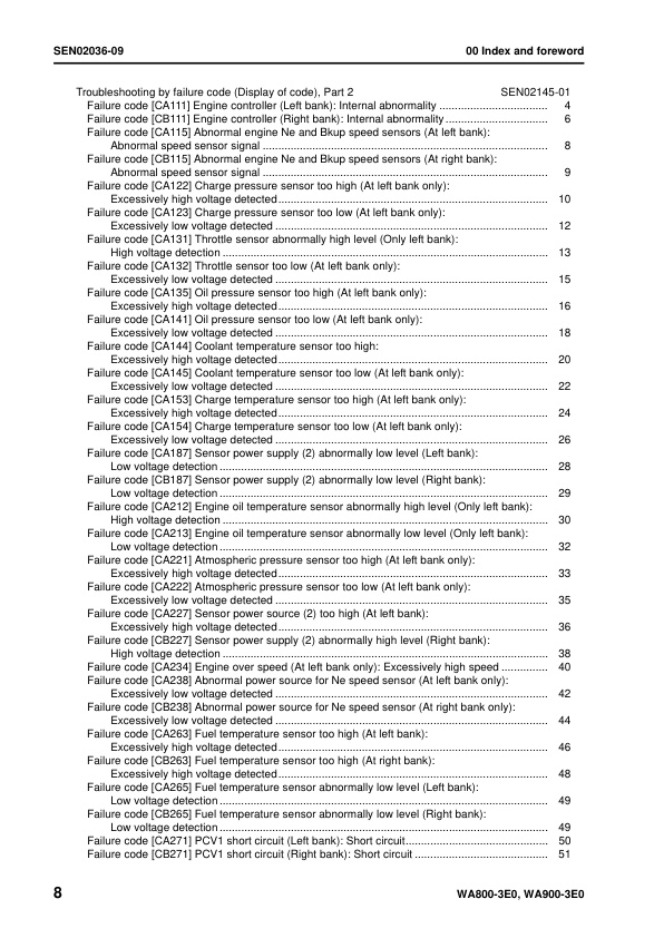
– Troubleshooting by failure code (Display of code), Part 2
— Failure code [CA111] Engine controller (Left bank): Internal abnormality
— Failure code [CB111] Engine controller (Right bank): Internal abnormality
— Failure code [CA115] Abnormal engine Ne and Bkup speed sensors (At left bank): Abnormal speed sensor signal
— Failure code [CB115] Abnormal engine Ne and Bkup speed sensors (At right bank): Abnormal speed sensor signal
— Failure code [CA122] Charge pressure sensor too high (At left bank only): Excessively high voltage detected
— Failure code [CA123] Charge pressure sensor too low (At left bank only): Excessively low voltage detected
— Failure code [CA131] Throttle sensor abnormally high level (Only left bank): High voltage detection
— Failure code [CA132] Throttle sensor too low (At left bank only): Excessively low voltage detected
— Failure code [CA135] Oil pressure sensor too high (At left bank only): Excessively high voltage detected
— Failure code [CA141] Oil pressure sensor too low (At left bank only): Excessively low voltage detected
— Failure code [CA144] Coolant temperature sensor too high: Excessively high voltage detected
— Failure code [CA145] Coolant temperature sensor too low (At left bank only): Excessively low voltage detected
— Failure code [CA153] Charge temperature sensor too high (At left bank only): Excessively high voltage detected
— Failure code [CA154] Charge temperature sensor too low (At left bank only): Excessively low voltage detected
— Failure code [CA187] Sensor power supply (2) abnormally low level (Left bank): Low voltage detection
— Failure code [CB187] Sensor power supply (2) abnormally low level (Right bank): Low voltage detection
— Failure code [CA212] Engine oil temperature sensor abnormally high level (Only left bank): High voltage detection
— Failure code [CA213] Engine oil temperature sensor abnormally low level (Only left bank): Low voltage detection
— Failure code [CA221] Atmospheric pressure sensor too high (At left bank only): Excessively high voltage detected
— Failure code [CA222] Atmospheric pressure sensor too low (At left bank only): Excessively low voltage detected
— Failure code [CA227] Sensor power source (2) too high (At left bank): Excessively high voltage detected
— Failure code [CB227] Sensor power supply (2) abnormally high level (Right bank): High voltage detection
— Failure code [CA234] Engine over speed (At left bank only): Excessively high speed
— Failure code [CA238] Abnormal power source for Ne speed sensor (At left bank only): Excessively low voltage detected
— Failure code [CB238] Abnormal power source for Ne speed sensor (At right bank only): Excessively low voltage detected
— Failure code [CA263] Fuel temperature sensor too high (At left bank): Excessively high voltage detected
— Failure code [CB263] Fuel temperature sensor too high (At right bank): Excessively high voltage detected
— Failure code [CA265] Fuel temperature sensor abnormally low level (Left bank): Low voltage detection
— Failure code [CB265] Fuel temperature sensor abnormally low level (Right bank): Low voltage detection
— Failure code [CA271] PCV1 short circuit (Left bank): Short circuit
— Failure code [CB271] PCV1 short circuit (Right bank): Short circuit
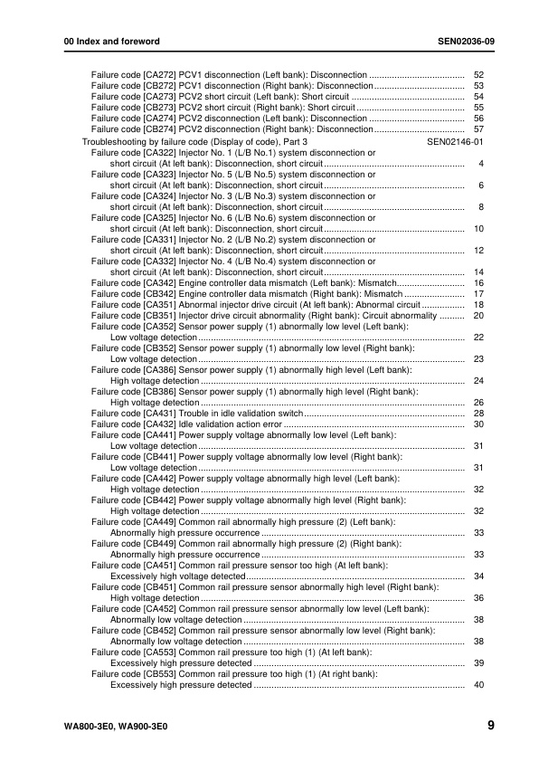
— Failure code [CA272] PCV1 disconnection (Left bank): Disconnection
— Failure code [CB272] PCV1 disconnection (Right bank): Disconnection
— Failure code [CA273] PCV2 short circuit (Left bank): Short circuit
— Failure code [CB273] PCV2 short circuit (Right bank): Short circuit
— Failure code [CA274] PCV2 disconnection (Left bank): Disconnection
— Failure code [CB274] PCV2 disconnection (Right bank): Disconnection
– Troubleshooting by failure code (Display of code), Part 3
— Failure code [CA322] Injector No. 1 (L/B No.1) system disconnection or short circuit (At left bank): Disconnection, short circuit
— Failure code [CA323] Injector No. 5 (L/B No.5) system disconnection or short circuit (At left bank): Disconnection, short circuit
— Failure code [CA324] Injector No. 3 (L/B No.3) system disconnection or short circuit (At left bank): Disconnection, short circuit
— Failure code [CA325] Injector No. 6 (L/B No.6) system disconnection or short circuit (At left bank): Disconnection, short circuit
— Failure code [CA331] Injector No. 2 (L/B No.2) system disconnection or short circuit (At left bank): Disconnection, short circuit
— Failure code [CA332] Injector No. 4 (L/B No.4) system disconnection or short circuit (At left bank): Disconnection, short circuit
— Failure code [CA342] Engine controller data mismatch (Left bank): Mismatch
— Failure code [CB342] Engine controller data mismatch (Right bank): Mismatch
— Failure code [CA351] Abnormal injector drive circuit (At left bank): Abnormal circuit
— Failure code [CB351] Injector drive circuit abnormality (Right bank): Circuit abnormality
— Failure code [CA352] Sensor power supply (1) abnormally low level (Left bank): Low voltage detection
— Failure code [CB352] Sensor power supply (1) abnormally low level (Right bank): Low voltage detection
— Failure code [CA386] Sensor power supply (1) abnormally high level (Left bank): High voltage detection
— Failure code [CB386] Sensor power supply (1) abnormally high level (Right bank): High voltage detection
— Failure code [CA431] Trouble in idle validation switch
— Failure code [CA432] Idle validation action error
— Failure code [CA441] Power supply voltage abnormally low level (Left bank): Low voltage detection
— Failure code [CB441] Power supply voltage abnormally low level (Right bank): Low voltage detection
— Failure code [CA442] Power supply voltage abnormally high level (Left bank): High voltage detection
— Failure code [CB442] Power supply voltage abnormally high level (Right bank): High voltage detection
— Failure code [CA449] Common rail abnormally high pressure (2) (Left bank): Abnormally high pressure occurrence
— Failure code [CB449] Common rail abnormally high pressure (2) (Right bank): Abnormally high pressure occurrence
— Failure code [CA451] Common rail pressure sensor too high (At left bank): Excessively high voltage detected
— Failure code [CB451] Common rail pressure sensor abnormally high level (Right bank): High voltage detection
— Failure code [CA452] Common rail pressure sensor abnormally low level (Left bank): Abnormally low voltage detection
— Failure code [CB452] Common rail pressure sensor abnormally low level (Right bank): Abnormally low voltage detection
— Failure code [CA553] Common rail pressure too high (1) (At left bank): Excessively high pressure detected
— Failure code [CB553] Common rail pressure too high (1) (At right bank): Excessively high pressure detected
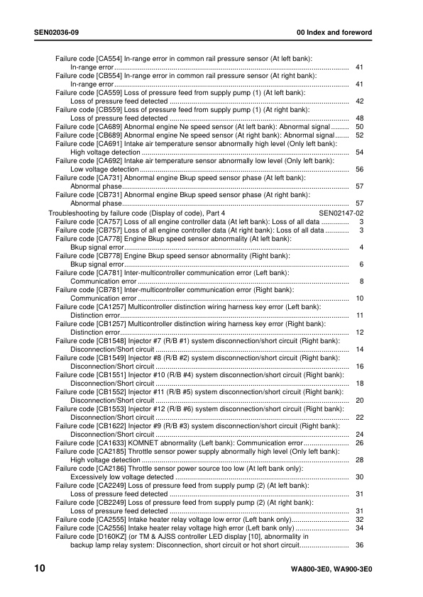
— Failure code [CA554] In-range error in common rail pressure sensor (At left bank): In-range error
— Failure code [CB554] In-range error in common rail pressure sensor (At right bank): In-range error
— Failure code [CA559] Loss of pressure feed from supply pump (1) (At left bank): Loss of pressure feed detected
— Failure code [CB559] Loss of pressure feed from supply pump (1) (At right bank): Loss of pressure feed detected
— Failure code [CA689] Abnormal engine Ne speed sensor (At left bank): Abnormal signal
— Failure code [CB689] Abnormal engine Ne speed sensor (At right bank): Abnormal signal
— Failure code [CA691] Intake air temperature sensor abnormally high level (Only left bank): High voltage detection
— Failure code [CA692] Intake air temperature sensor abnormally low level Failure code [CA692] Intake air temperature sensor abnormally low level
— Failure code [CA731] Abnormal engine Bkup speed sensor phase (At left bank): Abnormal phase
— Failure code [CB731] Abnormal engine Bkup speed sensor phase (At right bank): Abnormal phase
– Troubleshooting by failure code (Display of code), Part 4
— Failure code [CA757] Loss of all engine controller data (At left bank): Loss of all data
— Failure code [CB757] Loss of all engine controller data (At right bank): Loss of all data
— Failure code [CA778] Engine Bkup speed sensor abnormality (At left bank): Bkup signal error
— Failure code [CB778] Engine Bkup speed sensor abnormality (Right bank): Bkup signal error
— Failure code [CA781] Inter-multicontroller communication error (Left bank): Communication error
— Failure code [CB781] Inter-multicontroller communication error (Right bank): Communication error
— Failure code [CA1257] Multicontroller distinction wiring harness key error (Left bank): Distinction error
— Failure code [CB1257] Multicontroller distinction wiring harness key error (Right bank): Distinction error
— Failure code [CB1548] Injector #7 (R/B #1) system disconnection/short circuit (Right bank): Disconnection/Short circuit
— Failure code [CB1549] Injector #8 (R/B #2) system disconnection/short circuit (Right bank): Disconnection/Short circuit
— Failure code [CB1551] Injector #10 (R/B #4) system disconnection/short circuit (Right bank): Disconnection/Short circuit
— Failure code [CB1552] Injector #11 (R/B #5) system disconnection/short circuit (Right bank): Disconnection/Short circuit
— Failure code [CB1553] Injector #12 (R/B #6) system disconnection/short circuit (Right bank): Disconnection/Short circuit
— Failure code [CB1622] Injector #9 (R/B #3) system disconnection/short circuit (Right bank): Disconnection/Short circuit
— Failure code [CA1633] KOMNET abnormality (Left bank): Communication error
— Failure code [CA2185] Throttle sensor power supply abnormally high level (Only left bank): High voltage detection
— Failure code [CA2186] Throttle sensor power source too low (At left bank only): Excessively low voltage detected
— Failure code [CA2249] Loss of pressure feed from supply pump (2) (At left bank): Loss of pressure feed detected
— Failure code [CB2249] Loss of pressure feed from supply pump (2) (At right bank): Loss of pressure feed detected
— Failure code [CA2555] Intake heater relay voltage low error (Left bank only)
— Failure code [CA2556] Intake heater relay voltage high error (Left bank only)
— Failure code [D160KZ] (or TM & AJSS controller LED display [10], abnormality in backup lamp relay system: Disconnection, short circuit or hot short circuit
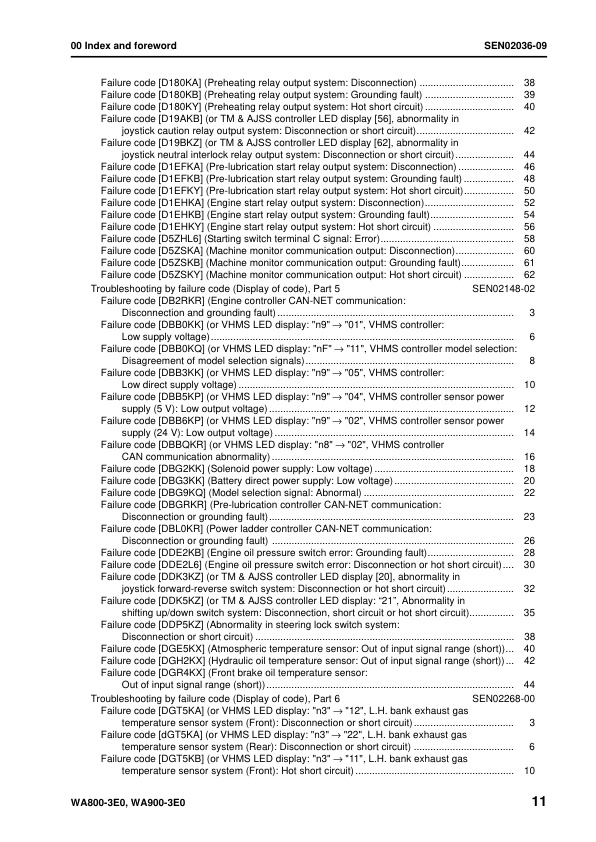
— Failure code [D180KA] (Preheating relay output system: Disconnection)
— Failure code [D180KB] (Preheating relay output system: Grounding fault)
— Failure code [D180KY] (Preheating relay output system: Hot short circuit)
— Failure code [D19AKB] (or TM & AJSS controller LED display [56], abnormality in joystick caution relay output system: Disconnection or short circuit)
— Failure code [D19BKZ] (or TM & AJSS controller LED display [62], abnormality in joystick neutral interlock relay output system: Disconnection or short circuit)
— Failure code [D1EFKA] (Pre-lubrication start relay output system: Disconnection)
— Failure code [D1EFKB] (Pre-lubrication start relay output system: Grounding fault)
— Failure code [D1EFKY] (Pre-lubrication start relay output system: Hot short circuit)
— Failure code [D1EHKA] (Engine start relay output system: Disconnection)
— Failure code [D1EHKB] (Engine start relay output system: Grounding fault)
— Failure code [D1EHKY] (Engine start relay output system: Hot short circuit)
— Failure code [D5ZHL6] (Starting switch terminal C signal: Error)
— Failure code [D5ZSKA] (Machine monitor communication output: Disconnection)
— Failure code [D5ZSKB] (Machine monitor communication output: Grounding fault)
— Failure code [D5ZSKY] (Machine monitor communication output: Hot short circuit)
– Troubleshooting by failure code (Display of code), Part 5
— Failure code [DB2RKR] (Engine controller CAN-NET communication: Disconnection and grounding fault)
— Failure code [DBB0KK] (or VHMS LED display: “n9” → “01”, VHMS controller: Low supply voltage)
— Failure code [DBB0KQ] (or VHMS LED display: “nF” → “11”, VHMS controller model selection: Disagreement of model selection signals)
— Failure code [DBB3KK] (or VHMS LED display: “n9” → “05”, VHMS controller: Low direct supply voltage)
— Failure code [DBB5KP] (or VHMS LED display: “n9” → “04”, VHMS controller sensor power supply (5 V): Low output voltage)
— Failure code [DBB6KP] (or VHMS LED display: “n9” → “02”, VHMS controller sensor power supply (24 V): Low output voltage)
— Failure code [DBBQKR] (or VHMS LED display: “n8” → “02”, VHMS controller CAN communication abnormality)
— Failure code [DBG2KK] (Solenoid power supply: Low voltage)
— Failure code [DBG3KK] (Battery direct power supply: Low voltage)
— Failure code [DBG9KQ] (Model selection signal: Abnormal)
— Failure code [DBGRKR] (Pre-lubrication controller CAN-NET communication: Disconnection or grounding fault)
— Failure code [DBL0KR] (Power ladder controller CAN-NET communication: Disconnection or grounding fault)
— Failure code [DDE2KB] (Engine oil pressure switch error: Grounding fault)
— Failure code [DDE2L6] (Engine oil pressure switch error: Disconnection or hot short circuit)
— Failure code [DDK3KZ] (or TM & AJSS controller LED display [20], abnormality in joystick forward-reverse switch system: Disconnection or hot short circuit)
— Failure code [DDK5KZ] (or TM & AJSS controller LED display: “21”, Abnormality in shifting up/down switch system: Disconnection, short circuit or hot short circuit)
— Failure code [DDP5KZ] (Abnormality in steering lock switch system: Disconnection or short circuit)
— Failure code [DGE5KX] (Atmospheric temperature sensor: Out of input signal range (short))
— Failure code [DGH2KX] (Hydraulic oil temperature sensor: Out of input signal range (short))
— Failure code [DGR4KX] (Front brake oil temperature sensor: Out of input signal range (short))
– Troubleshooting by failure code (Display of code), Part 6
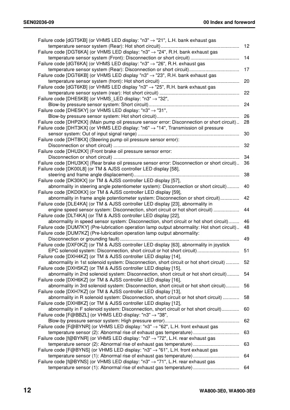
— Failure code [DGT5KA] (or VHMS LED display: “n3” → “12”, L.H. bank exhaust gas temperature sensor system (Front): Disconnection or short circuit)
— Failure code [dGT5KA] (or VHMS LED display: “n3” → “22”, L.H. bank exhaust gas temperature sensor system (Rear): Disconnection or short circuit)
— Failure code [DGT5KB] (or VHMS LED display: “n3” → “11”, L.H. bank exhaust gas temperature sensor system (Front): Hot short circuit)
— Failure code [dGT5KB] (or VHMS LED display: “n3” → “21”, L.H. bank exhaust gas temperature sensor system (Rear): Hot short circuit)
— Failure code [DGT6KA] (or VHMS LED display: “n3” → “24”, R.H. bank exhaust gas temperature sensor system (Front): Disconnection or short circuit)
— Failure code [dGT6KA] (or VHMS LED display: “n3” → “26”, R.H. exhaust gas temperature sensor system (Rear): Disconnection or short circuit)
— Failure code [DGT6KB] (or VHMS LED display “n3” → “23”, R.H. bank exhaust gas temperature sensor system (front): Hot short circuit)
— Failure code [dGT6KB] (or VHMS LED display “n3” → “25”, R.H. bank exhaust gas temperature sensor system (rear): Hot short circuit)
— Failure code [DHE5KB] (or VHMS_LED display: “n3” → “32”, Blow-by pressure sensor system: Short circuit)
— Failure code [DHE5KY] (or VHMS LED display: “n3” → “31”, Blow-by pressure sensor system: Hot short circuit)
— Failure code [DHP2KX] (Main pump oil pressure sensor error: Disconnection or short circuit)
— Failure code [DHT3KX] (or VHMS LED display: “n6” → “14”, Transmission oil pressure sensor system: Out of input signal range)
— Failure code [DHT8KX] (Steering pump oil pressure sensor error): Disconnection or short circuit)
— Failure code [DHU2KX] (Front brake oil pressure sensor error: Disconnection or short circuit)
— Failure code [DHU3KX] (Rear brake oil pressure sensor error: Disconnection or short circuit)
— Failure code [DK00L8] (or TM & AJSS controller LED display [58], steering and frame angle displacement)
— Failure code [DK30KX] (or TM & AJSS controller LED display [57], abnormality in steering angle potentiometer system): Disconnection or short circuit)
— Failure code [DKD0KX] (or TM & AJSS controller LED display [59], abnormality in frame angle potentiometer system: Disconnection or short circuit)
— Failure code [DLE4KA] (or TM & AJSS controller LED display [23], abnormality in engine speed sensor system: Disconnection, short circuit or hot short circuit)
— Failure code [DLT4KA] (or TM & AJSS controller LED display [22], abnormality in speed sensor system: Disconnection, short circuit or hot short circuit)
— Failure code [DUM7KY] (Pre-lubrication operation lamp output abnormality: Hot short circuit)
— Failure code [DUM7KZ] (Pre-lubrication operation lamp output abnormality: Disconnection or grounding fault)
— Failure code [DXF0KZ] (or TM & AJSS controller LED display [63], abnormality in joystick EPC solenoid system: Disconnection, short circuit or hot short circuit)
— Failure code [DXH4KZ] (or TM & AJSS controller LED display [14], abnormality in 1st solenoid system: Disconnection, short circuit or hot short circuit)
— Failure code [DXH5KZ] (or TM & AJSS controller LED display [15], abnormality in 2nd solenoid system: Disconnection, short circuit or hot short circuit)
— Failure code [DXH6KZ] (or TM & AJSS controller LED display [16], abnormality in 3rd solenoid system: Disconnection, short circuit or hot short circuit)
— Failure code [DXH7KZ] (or TM & AJSS controller LED display [13], abnormality in R solenoid system: Disconnection, short circuit or hot short circuit)
— Failure code [DXH8KZ] (or TM & AJSS controller LED display [12], abnormality in F solenoid system: Disconnection, short circuit or hot short circuit)
— Failure code [F@BBZL] (or VHMS LED display: “n3” → “38”, Blow-by pressure sensor system: High pressure error)
— Failure code [F@BYNR] (or VHMS LED display: “n3” → “62”, L.H. front exhaust gas temperature sensor (2): Abnormal rise of exhaust gas temperature)
— Failure code [f@BYNR] (or VHMS LED display: “n3” → “72”, L.H. rear exhaust gas temperature sensor (2): Abnormal rise of exhaust gas temperature)
— Failure code [F@BYNS] (or VHMS LED display: “n3” → “61”, L.H. front exhaust gas temperature sensor (1): Abnormal rise of exhaust gas temperature)
— Failure code [f@BYNS] (or VHMS LED display: “n3” → “71”, L.H. rear exhaust gas temperature sensor (1): Abnormal rise of exhaust gas temperature)
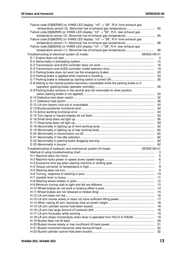
— Failure code [F@BZNR] (or VHMS LED display: “n3” → “82”, R.H. front exhaust gas temperature sensor (2): Abnormal rise of exhaust gas temperature)
— Failure code [f@BZNR] (or VHMS LED display: “n3” → “92”, R.H. rear exhaust gas temperature sensor (2): Abnormal rise of exhaust gas temperature)
— Failure code [F@BZNS] (or VHMS LED display: “n3” → “38”, R.H. front exhaust gas temperature sensor (1): Abnormal rise of exhaust gas temperature)
— Failure code [f@BZNS] (or VHMS LED display: “n3” → “39”, R.H. rear exhaust gas temperature sensor (1): Abnormal rise of exhaust gas temperature)
– Troubleshooting of electrical system (E-mode)
— E-1 Engine does not start
— E-2 Abnormality in preheating system
— E-3 Transmission and AJSS controller does not work
— E-4 Transmission and AJSS controller model selection error
— E-5 Parking brake does not work (as the emergency brake)
— E-6 Parking brake is applied while machine is traveling
— E-7 Parking brake is released as starting switch is turned ON
— E-8 Setting to the neutral position becomes unavailable while the parking brake is in operation (parking brake operates normally)
— E-9 Parking brake remains in the neutral and not removable to other position (when parking brake is not applied)
— E-10 Defective kick-down switch
— E-11 Defective hold switch
— E-12 Lift arm (boom) kick-out is unavailable
— E-13 Bucket positioner functional error
— E-14 Active working functional error
— E-15 Turn signal or hazard display do not flash
— E-16 Small lamp does not light up
— E-17 Head lamp does not light up
— E-18 Abnormality in lighting up of front working lamp
— E-19 Abnormality in lighting up of rear working lamp
— E-20 Abnormality in transmission cut-off
— E-21 Abnormality in low idle selection
— E-22 Abnormality in parking brake dragging warning
— E-23 Abnormality in buzzer
– Troubleshooting of hydraulic and mechanical system (H-mode)
— Method of using troubleshooting chart
— H-1 Machine does not move
— H-2 Machine lacks power or speed (every speed range)
— H-3 Excessive time lag when starting machine or shifting gear
— H-4 Torque converter oil temperature is high
— H-5 Steering does not turn
— H-6 Turning, response of steering is poor
— H-7 Joystick lever is heavy
— H-8 Steering wheel shakes or jerks
— H-9 Minimum turning radii to right and left are different
— H-10 Wheel brakes do not work or braking effect is poor
— H-11 Wheel brakes are not released or brakes drag
— H-12 Lift arm does not rise
— H-13 Lift arm moves slowly or does not have sufficient lifting power
— H-14 When raising lift arm, becomes slow at certain height
— H-15 Lift arm cylinder cannot hold down bucket
— H-16 Lift arm has large amount of hydraulic drift
— H-17 Lift arm fluctuates while working
— H-18 Lift arm drops momentarily when lever is operated from HOLD to RAISE
— H-19 Bucket does not tilt back
— H-20 Bucket moves slowly or has insufficient tilt back power
— H-21 Bucket movement becomes slow during tilt back
— H-22 Bucket cylinder cannot hold down bucket
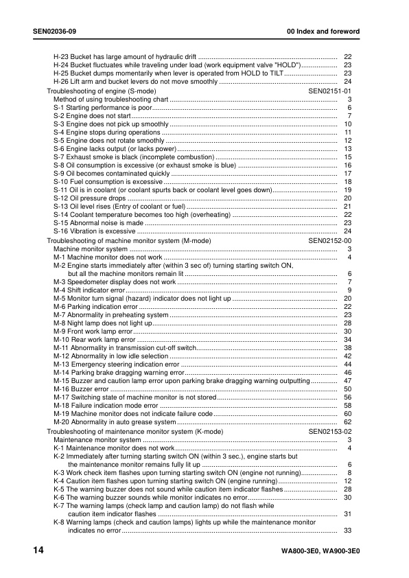
— H-23 Bucket has large amount of hydraulic drift
— H-24 Bucket fluctuates while traveling under load (work equipment valve “HOLD”)
— H-25 Bucket dumps momentarily when lever is operated from HOLD to TILT
— H-26 Lift arm and bucket levers do not move smoothly
– Troubleshooting of engine (S-mode)
— Method of using troubleshooting chart
— S-1 Starting performance is poor
— S-2 Engine does not start
— S-3 Engine does not pick up smoothly
— S-4 Engine stops during operations
— S-5 Engine does not rotate smoothly
— S-6 Engine lacks output (or lacks power)
— S-7 Exhaust smoke is black (incomplete combustion)
— S-8 Oil consumption is excessive (or exhaust smoke is blue)
— S-9 Oil becomes contaminated quickly
— S-10 Fuel consumption is excessive
— S-11 Oil is in coolant (or coolant spurts back or coolant level goes down)
— S-12 Oil pressure drops
— S-13 Oil level rises (Entry of coolant or fuel)
— S-14 Coolant temperature becomes too high (overheating)
— S-15 Abnormal noise is made
— S-16 Vibration is excessive
– Troubleshooting of machine monitor system (M-mode)
— Machine monitor system
— M-1 Machine monitor does not work
— M-2 Engine starts immediately after (within 3 sec of) turning starting switch ON, but all the machine monitors remain lit
— M-3 Speedometer display does not work
— M-4 Shift indicator error
— M-5 Monitor turn signal (hazard) indicator does not light up
— M-6 Parking indication error
— M-7 Abnormality in preheating system
— M-8 Night lamp does not light up
— M-9 Front work lamp error
— M-10 Rear work lamp error
— M-11 Abnormality in transmission cut-off switch
— M-12 Abnormality in low idle selection
— M-13 Emergency steering indication error
— M-14 Parking brake dragging warning error
— M-15 Buzzer and caution lamp error upon parking brake dragging warning outputting
— M-16 Buzzer error
— M-17 Switching state of machine monitor is not stored
— M-18 Failure indication mode error
— M-19 Machine monitor does not indicate failure code
— M-20 Abnormality in auto grease system
– Troubleshooting of maintenance monitor system (K-mode)
— Maintenance monitor system
— K-1 Maintenance monitor does not work
— K-2 Immediately after turning starting switch ON (within 3 sec.), engine starts but the maintenance monitor remains fully lit up
— K-3 Work check item flashes upon turning starting switch ON (engine not running)
— K-4 Caution item flashes upon turning starting switch ON (engine running)
— K-5 The warning buzzer does not sound while caution item indicator flashes
— K-6 The warning buzzer sounds while monitor indicates no error
— K-7 The warning lamps (check lamp and caution lamp) do not flash while caution item indicator flashes
— K-8 Warning lamps (check and caution lamps) lights up while the maintenance monitor indicates no error
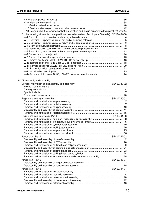
— K-9 Night lamp does not light up
— K-10 Night lamp remains lit up
— K-11 Service meter does not work
— K-12 Service meter keeps on working (when engine stops)
— K-13 Gauge items (fuel, engine coolant temperature and torque converter oil temperature) error
– Troubleshooting of remote boom positioner controller system (if equipped) (W-mode)
— W-1 Short circuit, disconnection in dumping solenoid system
— W-2 Short circuit in power source at hot end of dumping solenoid
— W-3 Short circuit in power source at return end of dumping solenoid
— W-4 Boom kick-out function trouble
— W-5 Disconnection in boom RAISE, LOWER detection pressure switch
— W-6 Short circuit, disconnection in boom angle potentiometer system
— W-7 Sensor cannot be adjusted
— W-8 Abnormality in engine speed signal system
— W-9 Remote positioner RAISE, LOWER LEDs do not light up
— W-10 Remote positioner RAISE set LED does not flash
— W-11 Remote positioner LOWER set LED does not flash
— W-12 Buzzer for switch operation does not sound
— W-13 Shock when stopping boom
— W-14 Short circuit in boom RAISE, LOWER pressure detection switch
50 Disassembly and assembly
– General information on disassembly and assembly
— How to read this manual
— Coating materials list
— Special tools list
— Sketches of special tools
– Engine and cooling system, Part 1
— Removal and installation of engine assembly
— Removal and installation of radiator assembly
— Removal and installation of damper assembly
— Disassembly and assembly of damper assembly
— Removal and installation of fuel tank assembly
– Engine and cooling system, Part 2
— Removal and installation of right bank fuel supply pump assembly
— Removal and installation of left bank fuel supply pump assembly
— Removal and installation of cylinder head assembly
— Removal and installation of fuel injector assembly
— Removal and installation of engine front oil seal
— Removal and installation of engine rear oil seal
– Power train, Part 1
— Disassembly and assembly of transfer assembly
— Disassembly and assembly of PTO assembly
— Removal and installation of parking brake calipers assembly
— Disassembly and assembly of parking brake calipers assembly
— Removal and installation of parking brake pad
— Removal and installation of parking brake spring cylinder
— Removal and installation of torque converter and transmission assembly
– Power train, Part 2
— Disassembly and assembly of torque converter assembly
— Disassembly and assembly of transmission assembly
– Power train, Part 3
— Removal and installation of front axle assembly
— Removal and installation of rear axle assembly
— Removal and installation of center support assembly
— Disassembly and assembly of center support assembly
— Removal and installation of differential assembly
— Disassembly and assembly of differential assembly
— Disassembly and assembly of final drive assembly
– Brake system
— Removal and installation of brake assembly
— Disassembly and assembly of brake assembly
— Removal and installation of left brake valve assembly
— Removal and installation of right brake valve assembly
— Disassembly and assembly of accumulator charge valve
— Disassembly and assembly of slack adjuster
– Undercarriage and frame
— Removal and installation of center hinge pin
— Removal and installation of counterweight assembly
– Hydraulic system
— Removal and installation of hydraulic tank and filter case assembly
— Removal and installation of hydraulic pump assembly
— Removal and installation of work equipment control valve assembly
— Disassembly and assembly of work equipment control valve assembly
— Disassembly and assembly of PPC valve assembly
— Removal and installation of steering valve assembly
— Removal and installation of diverter valve assembly
— Disassembly and assembly of diverter valve assembly
— Removal and installation of Orbitroll assembly
— Removal of steering stop valve
— Disassembly and assembly of hydraulic cylinder assembly
– Work equipment
— Removal and installation of work equipment assembly
— Replacement of boom front bushing
– Cab and its attachments
— Removal and installation of operator cab assembly
— Removal and installation of floor frame assembly
— Disassembly and assembly of operator’s seat assembly
– Electrical system
— Removal and installation of engine controller assembly
— Removal and installation of transmission and steering controller assembly
— Removal and installation of main monitor assembly
— Removal and installation of air conditioner unit assembly
90 Diagrams and drawings
– Hydraulic diagrams and drawings
— Power train hydraulic circuit diagram
— Brake hydraulic circuit diagram
— Work equipment hydraulic circuit diagram
– Electrical diagrams and drawings
— Electrical circuit diagram (1/8)
— Electrical circuit diagram (2/8)
— Electrical circuit diagram (3/8)
— Electrical circuit diagram (4/8)
— Electrical circuit diagram (5/8)
— Electrical circuit diagram (6/8)
— Electrical circuit diagram (7/8)
— Electrical circuit diagram (8/8)
— Electrical circuit diagram of emergency engine stop
— Electrical circuit diagram of hydraulic oil level sensor
— Electrical circuit diagram of battery and starting motor disconnector switch and starting aid connector
— Connector arrangement diagram
Reviews
There are no reviews yet.