


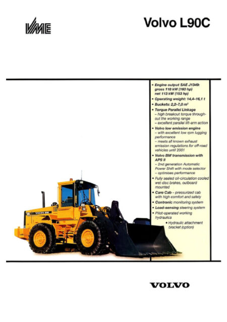
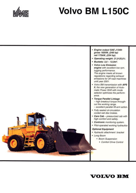
Volvo BM L120C Wheel Loader 2020 (Preview)
COVER
DESCRIPTIONS
(0) GENERAL
Description
Product Identification Plates
(1) STANDARD PARTS, SERVICE
After towing recovering
Charging batteries
Cleanliness when working on brake and hydraulic system
Electric welding
Emergency release of parking brake
Removing propeller shafts
Repairing hydraulic system
Towing Recovering
(2) ENGINE WITH MOUNTING AND EQUIPMENT
Description
(3) ELEC. SYSTEM; WARNING SYSTEM; INFORMATION SYSTEM; INSTRUMENTS
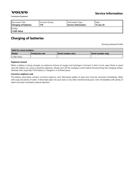
Charging batteries
Contronic Display Unit
Contronic System
Electrical distribution box
Functions which not are included in the Central warning
General description
Instruments and controls
Monitored functions
Operating with the ecu disconnected
Other electrical functions (controlled by the control unit)
Special instructions when working on the electrical system
Units connected to the control unit
(4) POWER TRANSMISSION
APS II (Automatic Power Shift with Mode Selector)
Description
Gear selector valve
Operating with the ecu disconnected
Symbol diagram HT131
Symbol diagram HT205
(5) BRAKE
Description, L90C
Description, L120C
Description
Function
(6) STEERING
Description (Applies to L90C)
Description (Applies to L120C)
Function, secondary steering, Fig. 28
Pump and pressure and flow compensators neutral position (Fig. 4)
Pump and pressure and flow compensators neutral position (Fig. 10)
Secondary steering system
Shift valve neutral position (Fig. 13)
Testing function
(7) FRAME; SPRINGS; DAMPING; AXLE SUSPENSION; WHEEL, TRACK UNIT
General description
(8) MACHINERY HOUSE; CAB; EXTERIOR TRIM PARTS ANYWHERE
AC safety
Air conditioning (ac)
Description
Electrical system, air conditioning, description of function
Refrigerant in air conditioning
Wiring diagram, climate control system and air conditioning, circuit 22 1 — 22 8
(9) HYDRAULIC SYSTEM, DIGGING, HANDLING, GRADING EQUIPM, MISC. EQUIP
Chock and anti-cavitation functions
Control valve functions
Description
Hydraulic oil pump
Pressure back-up for servo circuit, accumulator checking
Servo pressure, checking and adjusting (Machine with separate attachment locking)
Servo pressure, checking and adjusting (Machine without separate attachment locking)
Servo pressure, checking at spool in control valve
Servo valve, controls, adjusting
Servo valve, function
Diagrams
(3) ELEC. SYSTEM; WARNING SYSTEM; INFORMATION SYSTEM; INSTRUMENTS
Code key for diodes
Codes used in wiring diagrams
Explanations to wiring diagrams (lead and component markings)
List of circuits
Wiring diagram, cicuit 11 — 110
Wiring diagram, cicuit 21 — 210
Wiring diagram, circuit 31 – 310
Wiring diagram, circuit 41 – 410
Wiring diagram, circuit 51 – 510
Wiring diagram, circuit 61 – 610
Wiring diagram, circuit 71 – 79
Wiring diagram, circuit 81 – 810
Wiring diagram, circuit 91 – 97
Wiring diagram, circuit 101 – 108
Wiring diagram, circuit 111 – 117
Wiring diagram, circuit 121 – 1210
Wiring diagram, circuit 131 – 1310
Wiring diagram, circuit 141 – 1410
Wiring diagram, circuit 151 – 157
Wiring diagram, circuit 161 – 168
Wiring diagram, circuit 171 – 175
Wiring diagram, circuit 181 – 188
Wiring diagram, circuit 191 – 197
Wiring diagram, circuit 201 – 207
Wiring diagram, circuit 211 – 217
Wiring diagram, circuit 221 – 228
Wiring diagram, circuit 231 – 238
Wiring diagram, circuit 241 – 246
Wiring diagram, circuit 251 – 259
(9) HYDRAULIC SYSTEM;DIGGING HANDING GRANDING EQUIPM.; MISC. EQUIP
Hydraulic diagram, working hydraulics
Installation Instruction
3rd hydraulic function
Air conditioning
Attachment bracket with attachment locking, (Optimal)
Attachment lock
Attachment locking
Care Track
Electrical engine heater
Engine heater, 120 V (USA)
Hip Belt
INSTALLATION KIT FOR OPERATORS SEAT (2)
INSTALLATION KIT FOR OPERATORS SEAT
Kit for fitting the radio
Protective grille, headlamp
Rotating Beacon
Sun blind
Windscreen washer
Working light, front
Working light, rear
REPAIR
(0) GENERAL
Time Guide
(2) ENGINE WITH MOUNTING AND EQUIPMENT
Checking speed with frequency meter
Fuel system, air bleeding
Idling speed, checking and adjusting
Injection advance angle, checking and adjusting
(3) ELEC. SYSTEM; WARNING SYSTEM; INFORMATION SYSTEM; INSTRUMENTS
Headlights, adjustment
(4) POWER TRANSMISSION
Checking oil pressures, transmission
Differential lock, adjusting
(5) BRAKE
Adjusting break pedal angle
Air bleeding brake system
Brake discs, changing
Brake discs, checking wear
Checking function
Hydraulic diagram
Pressure in circuit, checking and adjusting
Retardation, checking function
Unloading pressure, checking and adjusting
(6) STEERING
Steering cylinder
Steering valve, L120C
Working pressure and stand-by pressure, checking and adjusting
(9) HYDRAULIC SYSTEM, DIGGING, HANDLING, GRADING EQUIPM, MISC. EQUIP
Back-up valve, opening pressure, checking
Checking and adjusting shock valve, piston end of lifting cylinder
Hydraulic oil pump, working pressure, checking and adjusting
Lifting Tilting cylinder (principle diagram)
Shock valve, tilting function, checking and adjusting
Safety
(1) STANDARD PARTS, SERVICE
A few simple rules for batteries
A few simple rules of safety
A few simple rules when inflating tyres
A few simple rules when servicing
Charging batteries
Danger in connection with polymer materials
Measures to prevent fire
Refrigerant in air-conditioning units
Safety concerns everybody!
Service position
Starting with booster batteries
Specifications
(0) GENERAL.
Air conditioning
Capacities
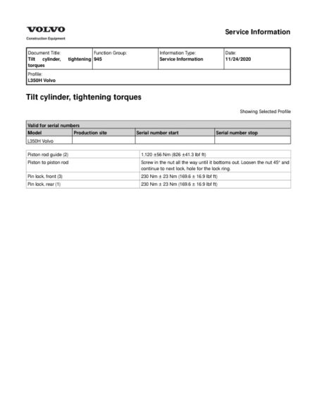
Volvo BM standard tightening torques
Weights, (approx.)
(2) ENGINE WITH MOUNTING AND EQUIPMENT
Specifications L90C
Specifications, L90C 2
Specifications, L90C 3
Specifications, L90C 4
Specifications, L90C 5
Specifications, L90C 6
Specifications, L90C 7
Specifications, L90C 8
Specifications, L90C 9
Specifications, L90C 10
Specifications, L90C
Specifications, L120C 2
Specifications, L120C 3
Specifications, L120C 4
Specifications, L120C 5
Specifications, L120C 6
Specifications, L120C 7
Specifications, L120C 8
Specifications, L120C 9
Specifications, L120C 10
Specifications, L120C 11
Specifications, L120C
(3) ELEC. SYSTEM; WARNING SYSTEM; INFORMATION SYSTEM; INSTRUMENTS
Specifications 2
Specifications 3
Specifications 4
Specifications, L90C 2
Specifications, L90C
Specifications, L120C 2
Specifications, L120C
Specifications
(4) POWER TRANSMISSION
Specifications, L90C 2
Specifications, L90C
Specifications, L120C 2
Specifications, L120C
(5) BRAKE
Specifications, L90C, L120C
Specifications, L90C
Specifications, L120C
(6) STEERING
Hydraulic diagram, L90C, basic machine
Hydraulic diagram, L120C, basic machine
Specifications, L90C
Specifications, L120C
(9) HYDRAULIC SYSTEM; DIGGING HANDLING GRADING EQUIPM; MISC. EQUIP
Specicifations, L90C, L120C
Specifications, Boom suspension system L90C
Specifications, Boom suspension system L120C
Specifications, L90C
Specifications, L120C

There are no reviews yet.