


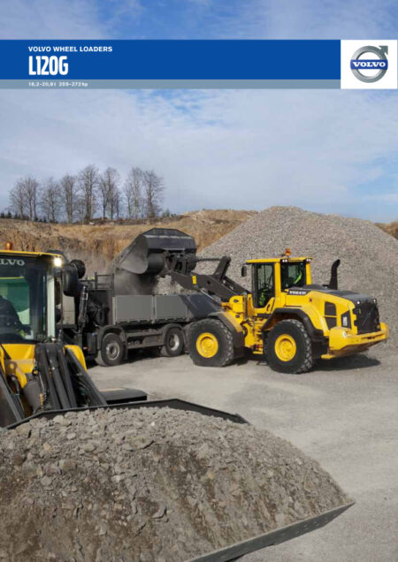
Volvo BM L180 CO Wheel Loader 2020 (Preview)
COVER
DESCRIPTIONS
(0) GENERAL
Description
Product Identification Plates L150
Product Identification Plates L180
(1) STANDARD PARTS, SERVICE
Charging batteries
Cleanliness when working on brake and hydraulic systems
Electric welding
Manual release of parking brake
Repairing hydraulic system
Towing
(2) ENGINE WITH MOUNTING AND EQUIPMENT
Bleeding fuel system
Checking function, engine
Description
Injection system, low-emission engine
Intercooler
Specifications L150
Specifications L180
Starting engine
Starting low-emission engine
Stop solenoid, fitting
Stop solenoid
(3) ELEC. SYSTEM; WARNING SYSTEM; INFORMATION SYSTEM; INSTRUMENTS
Charging of batteries
Contronic Display Unit
Contronic System
Description
Electrical distribution box in cab
Electrical distribution box
Emergency operation, electrical
Functions not included in the central warning
Instruments and controls
Monitored functions
Monitoring transmission filter
Other electrical functions
Special instructions when working on the electrical system
Units (functions) connected to the control unit
(4) POWER TRANSMISSION
APS (Automatic Power Shift)
Description
Differential carrier assembly EV85, L150 up to and incl. se. no. 1233
Differential carrier assembly, AWB40, (L150 w.e.fr. se. no. 1234 and L180)
Differential carrier assembly, Changing L150 w.e.fr. se. no. 1234 and L180 (AWB40)
Downshifting switch, engine braking
Dual control, gear shifting forward – reverse
Engine power reduction when changing travelling direction
Fitting rear axle
Gear selector valve Transmission
Gear selector valve
Gear shifting, signal to the ECU from the selector control
Hub reduction, Changing seal, One side L150 up to and incl. se. no. 1233 (with drive axles AH65 and 70)
Operating with ECU disconnected
Planetary gear, AH70N, (L150 up to and incl. se. no. 1233)
Planetary gear, AWB40, (L150 w.e.fr. se. no. 1234 up to and incl. 1595 and L180 up to and incl. se. no. 1327)
Planetary gear, AWB40,
Removing rear axle
Transmission HT210 HT220
Transmission, Checking oil pressure
Transmission, Fault tracing
Transmission, Removing and fitting
(5) BRAKE
Description (2)
Description
Function
Wiring diagram
(6) STEERING
Description (2)
Description (3)
Description
Hydraulic diagram, steering system, lever steering
Hydraulic diagram, steering system, secondary steering
Lever steering, adjusting steering speed
Reconditioning variable piston pump L180
Reconditioning variable piston pump, L150
Shift valve
Shock valves in valve block, checking
Steering lever, checking output voltage
Steering valve
Working pressure and stand-by pressure, checking and adjusting
(7) FRAME; SPRINGS; DAMPING; AXLE SUSPENSION; WHEEL, TRACK UNIT
Adjusting axial clearance, rear axle mounting
Changing bushing in axle mounting L150 w.e.fr. se. no. 1234 and L180
Description
Front rear axle bridge, L150 up to and incl. se. no. 1233
Front rear axle bridge, L150 w.e.fr. se. no. 1234 and L180
Measuring axial and radial clearance, rear axle mounting
Tightening torques
(8) MACHINERY HOUSE; CAB; EXTERIOR TRIM PARTS ANYWHERE
AC safety L150 up to and incl. ser. no. 1328
Air conditioning, performance test (R12 and R134a)
Description (2)
Description
Electrical system (2)
Electrical system
Refrigerants, R134a
Safety valve on receiver drier
(9) HYDRAULIC SYSTEM; DIGGING HANDLING GRADING EQUIPM; MISC. EQUIP
Attachment unlocking locking with Separate attachment locking
Boom kick-out and bucket positioner, adjusting
Boom kick-out, bucket positioner and floating position
Checking and adjusting shock valve, lifting cylinder piston end
Checking and adjusting shock valve, tilting function
Checking opening pressure, back-up valve
Control valve functions
Description
Detent function floating position and floating position
Detent function lifting boom kick-out (SW18)
Hydraulic diagram, L150 (2)
Hydraulic diagram, L150 basic machine
Hydraulic diagram, L150
Hydraulic diagram, L180 (2)
Hydraulic diagram, L180 basic machine
Hydraulic diagram, L180
Hydraulic pump
Lifting arm, changing bearings at lower bucket or attachment bracket pivoting points
Lifting cylinder (removed), changing bushings
Lifting cylinder, changing seals in machine
Lifting cylinder, changing
Lifting cylinder
Lifting frame
Separate attachment locking
Servo system
Shock and anti-cavitation functions
Tilting cylinder (removed), changing bearings
Tilting cylinder, changing seals in machine
Tilting cylinder, changing
Tilting cylinder
DIAGRAMS
(3) ELEC. SYSTEM; WARNING SYSTEM; INFORMATION SYSTEM; INSTRUMENTS
Code key for connectors (connected to the circuit board)
Code key for connectors (others)
Code key for diodes
Codes using in wiring diagrams
Explanations to wiring diagrams (Lead- and component marking)
List of Cicuits
Wiring diagram, circuit 1 1 — 1 10
Wiring diagram, circuit 2 1 — 2 10
Wiring diagram, circuit 3 1 — 3 10
Wiring diagram, circuit 4 1 — 4 10
Wiring diagram, circuit 5 1 — 5 10
Wiring diagram, circuit 6 1 — 6 10
Wiring diagram, circuit 7 1 — 7 9
Wiring diagram, circuit 8 1 — 8 10
Wiring diagram, circuit 9 1 — 9 7
Wiring diagram, circuit 10 1 — 10 8
Wiring diagram, circuit 11 1 — 11 7
Wiring diagram, circuit 12 1 — 12 9
Wiring diagram, circuit 13 1 — 13 10 (2)
Wiring diagram, circuit 13 1 — 13 10
Wiring diagram, circuit 14 1 — 14 7
Wiring diagram, circuit 15 1 — 15 5
Wiring diagram, circuit 16 1 — 16 8
Wiring diagram, circuit 17 1 — 17 7
Wiring diagram, circuit 18 1 — 18 7
Wiring diagram, circuit 19 1 — 19 7
Wiring diagram, circuit 20 1 — 20 7
Wiring diagram, circuit 20 1 — 20 10
Wiring diagram, circuit 21 1 — 21 10
Wiring diagram, circuit 22 1 — 22 9
INSTALLATION INSTRUCTIONS
CARE TRACK
REPAIR
(0) GENERAL
E-tools
Time Guide
(2) ENGINE WITH MOUNTING AND EQUIPMENT
Changing crankshaft front oil seal
Changing fuel tank
Checking and adjusting idling speed
Checking and adjusting injection timing
Checking stalling speed
Fitting engine
Oil sump gasket, changing including cleaning oil strainer
Removing engine
Speed, checking with frequency meter
(3) ELEC. SYSTEM; WARNING SYSTEM; INFORMATION SYSTEM; INSTRUMENTS
Headlamps, adjusting
(4) POWER TRANSMISSION
Adjusting differential lock
(5) BRAKE
Accumulator, Checking (Removed)
Bake discs, Checking wear L150 w.e.fr. ser. no. 1234 (with drive axles AWB40) and L180
Bleeding brake system
Brake discs, Changing L150 up to and incl. ser. no. 1233 (with drive axles AH65 and 70)
Brake discs, Changing L150 w.e.fr. ser. no. 1234 (with drive axles AWB40) and L180
Brake discs, Checking wear L150 up to and incl. ser. no. 1233 (with drive axles AH65 and 70)
Brake pedal, Adjusting pedal angle
Brake piston, Changing seals L150 w.e.fr. ser. no. 1234 (with drive axles AWB40) and L180
Brake system, Checking and adjusting pressure in circuit
Brake system, Checking and adjusting, Unloading pressure
Checking function, Brake system
Hydraulic diagram, brake system, (2)
Hydraulic diagram, brake system, (3)
Hydraulic diagram, brake system,
(7) FRAME; SPRINGS; DAMPING; AXLE SUSPENSION; WHEEL, TRACK UNIT
Frame joint, changing bearings and pins
(9) HYDRAULIC SYSTEM; DIGGING HANDLING GRADING EQUIPM; MISC. EQUIP
Accumulator, boom suspension system
Accumulator, changing seals
Accumulator, checking and adjusting
Changing or repairing hydraulic pumps
Checking closing pressure, pressure-reducing valves R1 and R2
Oil pump, (pump 2) checking and adjusting working pressure
Oil pump, checking and adjusting working pressure
Reconditioning hydraulic oil pump
Safety valve tb, checking opening pressure
Servo pressure, checking and adjusting
Servo pressure, checking at spool in control valve
Servo valve, adjusting controls
SAFETY
(1) STANDARD PARTS, SERVICE
A few simple rules for batteries
A few simple rules of safety
A few simple rules when inflating tyres
A few simple rules when servicing
Charging batteries
Danger in connection with polymer materials
Measures to preveent fire
Refrigerant in air-conditioning units
Safety concerns everybody!
Service position
Starting with booster batteries
SPECIFICATIONS
(0) GENERAL
Air conditioning (AC)
Capacities
Volvo BM standard tightening torques
Weights (approx.)
(2) ENGINE WITH MOUNTING AND EQUIPMENT
Specifications (2)
Specifications (3)
Specifications L150 (2)
Specifications L150 (3)
Specifications L150 (4)
Specifications L150 (5)
Specifications L150 (6)
Specifications L150
Specifications L180 (2)
Specifications L180 (3)
Specifications L180 (4)
Specifications L180 (5)
Specifications L180 (6)
Specifications L180
Specifications
(3) ELEC. SYSTEM; WARNING SYSTEM; INFORMATION SYSTEM; INSTRUMENTS
Specifications (2)
Specifications (3)
Specifications (4)
Specifications (5)
Specifications (6)
Specifications
(4) POWER TRANSMISSION
Specifiactions L180
Specifications L150 (2)
Specifications L150
Specifications L180
Tightening torques (2)
Tightening torques
(5) BRAKE
Specifications L150 (2)
Specifications L150
Specifications L180 (2)
Specifications L180
(6) STEERING
Hydraulic diagram, complete
Hydraulic diagram, steering system, basic machine
Specifications L150
Specifications L180
Tightening torques
(8) MACHINERY HOUSE; CAB; EXTERIOR TRIM PARTS ANYWHERE
Tightening torques
(9) HYDRAULIC SYSTEM; DIGGING HANDLING GRADING EQUIPM; MISC. EQUIP
Boom suspension system, boom suspension system for wheel loaders
Boom suspension system, checking function
Releasing the hydraulic oil pressure in the accumulators
Specifications L150
Specifications L180
Specifications, boom suspension system
Specifications, L150
Specifications, L180
Valve block, boom suspension system


There are no reviews yet.