AP26.00-D-2601A Manual transmission – oil change 25.02.2019.pdf
– AP26.00-D-2601A Manual transmission – oil change 25.02.2019
– Model 636 with transmission 716.65
– Model 638
– except code G40 (Automatic transmission)
– Model 639 with transmission 716.6
– except code MA0 (E-CELL 60 kW)
– Model 667 with transmission 711.11/13/61
– Model 668 with transmission 710.6, 712.21/613/621, 715.00/02/05
– Model 670 with transmission 710.6/84, 711.61, 712.21/613/621, 714.08/50, 715.00/02/05Model 690.6 with transmission 711.620
– Model 901, 902, 903, 904 with transmission 711.60/61
– Model 901, 902, 903, 904, 905 with transmission 711.62
– Modification notes
– Transmission in model 638
– Transmission 716 in model 636, 639
– N26.00-2319-01 S26.00-4500-01
– Transmission 711, 712, 715 (example)
– Transmission 710 (S5-42)
– N26.00-2268-01 N26.00-0286-01
AP26.00-G-2601E Manual transmission – oil change 14.7.10.pdf
– AP26.00-G-2601E Manual transmission – oil change 14.7.10
– TRANSMISSION 715.350 /351 /361 in MODEL 000.001
– TRANSMISSION 714.100 /120 /140 /143 /160 /161 in MODEL 000.001
– Shown on transmission 715.351
– 1 Oil filler plug
– Shown on transmission 714.140
– 1 Oil filler plug2 Oil drain screw3 Screw plug
– 1 Clean area around oil filler screw (1), oil drain Only change the oil when the transmission
– screw (2 and 6) and screw plug (3) on is at operating temperature.
– transmission housing
– 2 Remove oil filler screw (1)
AP26.00-G-2601OHA Manual transmission – oil change 20.12.2016.pdf
– AP26.00-G-2601OHA Manual transmission – oil change 20.12.2016
– Transmission 714.140/143 in model 000.001
– 1 Oil filler plug
– handling of transmission oil. Health risk and safety glasses.
– caused by swallowing transmission oil Do not pour transmission oil into beverage
– bottles.
– under transmission manufacturer.
– Clean
– Drain transmission oil
– 3 Remove oil filler screw (1)
– transmission fluid, unscrew drain screws (2) and completely drain automatic transmission
– fluid
– 5 Tighten cleaned drain screws (2) *BA26.40-N-1003-01H Oil drain screw to transmission housing
– Fill with transmission oil
AP26.00-G-2610E Manual transmission – check oil level correct 14.7.10.pdf
– AP26.00-G-2610E Manual transmission – check oil level, correct 14.7.10
– TRANSMISSION 715.350 /351 /361 in MODEL 000.001
– TRANSMISSION 714.100 /120 /140 /143 /160 /161 in MODEL 000.001
– Shown on transmission 715.351
– 1 Oil filler plug
– Shown on transmission 714.140
– 1 Clean area around oil filler screw (1) on Check oil level when transmission is cold.
– transmission housing
– 2 Remove oil filler screw (1)
– hole for the oil filler screw (1). Have a container at the ready to collect any discharged transmission oil. Clean oil filler screw (1). Observe Specifications for
– Operating Fluids:
AP26.00-G-2610OHA Manual transmission – check oil level correct 20.12.2016.pdf
– AP26.00-G-2610OHA Manual transmission – check oil level, correct 20.12.2016
– Transmission 714.140/143 in model 000.001
– 1 Oil filler plug
– handling of transmission oil. Health risk and safety glasses.
– caused by swallowing transmission oil Do not pour transmission oil into beverage
– bottles.
– under transmission manufacturer.
– Clean
– automatic transmission fluid and remove oil filler screw (1)
– 4 Check transmission oil level, if necessary
– refill up to lower edge of opening for oil filler Check transmission oil level only when
– screw (1) transmission is cold.
AP43.30-G-4301G Retarder – oil change 8.6.11.pdf
– MODEL 000.001 with TRANSMISSION 714.100 /120 /140 /143 /160 /161
– with Voith retarder R115E
AP43.30-G-4302OHA Perform oil change of hydrodynamic retarder 25.11.2016.pdf
– Model 000.001 with transmission 714.140/143
– Transmission with hydrodynamic retarder R115 E (integrated), Voith- 153.000188xx, H67.1500xx
– 1 Drain screw (hydrodynamic retarder)
AP43.30-G-4302OHB Perform oil change of hydrodynamic retarder 25.11.2016.pdf
– Model 000.001 with transmission 714.140/143
– Transmission with hydrodynamic retarder R115 E (integrated), Voith- 153.000452xx
– 1 Drain screw (hydrodynamic retarder)
– under transmission manufacturer.
– 4 Open maintenance flap covering See information from vehicle
AR25.20-G-0200B Remove and install clutch throwout lever 28.9.10.pdf
– MODEL 000.001 with TRANSMISSIONS 715.521 /560
– MODEL 000.001 with TRANSMISSION 714.100 /120 /140 /143 /160 /161
– 1 Screw
– 1 Remove transmission or engine See vehicle operator’s manual or repair
– instructions.
AR26.10-G-0001G Disassemble assemble transmission 27.2.12.pdf
– AR26.10-G-0001G Disassemble, assemble transmission 27.2.12
– TRANSMISSION 714.100 /120 /140 /143 /160 /161 in MODEL 000.001
– T26.10-0018-09
– Shown on transmission 714.140
– 1 Drive shaft bearing cap 13 Shift mechanism 18 Countershaft
– 5 Drive shaft 15 Sliding yoke (only transmission 19 Main shaft
– 714.14/16) 8 Countershaft bearing cover 20 Rear transmission housing
– 16 Shift forks 9 Countershaft shim 26 Rear transmission cover
– 17 Shift rails 11 Front transmission housing 35 Reverse gear wheel
– Disassemble
– 1 Drain transmission oil AP26.00-G-2601E
– 2 Remove transmission See vehicle operating/repair instructions.
– 3 Remove clutch housing AR26.30-G-0330G Only perform on transmission without
– integrated clutch housing.
– 4 Attach transmission to assembly device Universal assembly stand GS
– Adapter “GSA SKN” for transmission with integral clutch housing
– Adapter “GSA SKN 2” for transmission without integral clutch housing
AR26.10-G-0001OHA Disassemble assemble transmission 20.01.2017.pdf
– AR26.10-G-0001OHA Disassemble/assemble transmission 20.01.2017
– Transmission 714.140/143 in model 000.001
– T26.10-0018-09
– Shown on transmission without hydrodynamic retarder R115 (integrated), Voith
– 1 Drive shaft bearing cap 16 Shift forks
– 11 Front transmission housing 20 Rear transmission housing
– 13 Shift 26 Rear transmission cover
– 15 Sliding yoke 35 Reverse gearwheel
– 1 Drain transmission oil
– AP26.00-G-2601OHA
– 2 Remove the transmission See information provided by vehicle
– manufacturer or transmission manufacturer.
– 3 Detach clutch housing from front transmission Only on front transmission housing (11)
AR26.18-G-2000OHA Remove install gear shift cylinder 25.11.2016.pdf
– Transmission 714.140/143 in model 000.001
– Vehicle with electropneumatic power shift (EPS)
AR26.18-G-2100OHA Remove install gate shift cylinder 25.11.2016.pdf
– Transmission 714.140/143 in model 000.001
– Vehicle with electropneumatic power shift (EPS)
AR26.30-G-0310G Remove install rear transmission cover 2.3.12.pdf
– AR26.30-G-0310G Remove/install rear transmission cover 2.3.12
– TRANSMISSION 714.100 /120 /140 /143 /160 /161 in MODEL 000.001
– 1 Main shaft transmission cover
– 2 Countershaft transmission cover
– 3 Screw4 Screw
– 1 Drain transmission oil AP26.00-G-2601E Collect transmission oil in a suitable
– container if necessary so that it can be refilled into the transmission.
– 2 Remove output flange AR26.40-G-2475-03G
– main shaft transmission cover (1)
– 5 Detach main shaft transmission cover (1) from Installation: Install new O-ring. Coat
– transmission housing separating surface at oil return bore with
AR26.30-G-0310OHA Remove install rear transmission cover 20.01.2017.pdf
– AR26.30-G-0310OHA Remove/install rear transmission cover 20.01.2017
– Transmission 714.140/143 in model 000.001
– Transmission without hydrodynamic retarder R115 (integrated), Voith
– 1 Main shaft transmission cover
– 2 Countershaft transmission cover
– 3 Screw plug
– handling of transmission oil. Health risk and safety glasses.
– caused by swallowing transmission oil Do not pour transmission oil into beverage
– bottles.
– *BA26.50-N-1004-01P Stretch bolt, output flange to transmission
– main shaft
– transmission oil in a suitable receptacle
– 3 Detach speed sensor (4) from main shaft *BA26.19-N-1003-01F Speedometer sensor to rear transmission
– transmission cover (1) cover
– 4 Detach main shaft transmission cover (1) Installation: Replace O-ring.
– from transmission housing
AR26.30-G-0315G Disassembling and assembling rear transmission cover 14.7.10.pdf
– AR26.30-G-0315G Disassembling and assembling rear transmission cover 14.7.10
– TRANSMISSION 714.100 /120 /140 /143 /160 /161 in MODEL 000.001
– Transmission without Voith retarder R115E
– 1 Radial shaft sealing ring
– 3 Main shaft transmission cover
– T26.30-0015-01
– 1 Remove main shaft transmission cover (3) AR26.30-G-0310G
– 2 Measure and note the installation depth of the
AR26.30-G-0315OHA Disassembling and assembling rear transmission cover 28.11.2016.pdf
– AR26.30-G-0315OHA Disassembling and assembling rear transmission cover 28.11.2016
– Transmission 714.140/143 in model 000.001
– Transmission without hydrodynamic retarder R115 (integrated), Voith
– 1 Radial shaft sealing ring
– 3 Rear transmission cover
– T26.30-0015-01
– 1 Remove rear transmission cover (3) AR26.30-G-0310OHA
– 2 Remove O-ring (2)
– transmission cover (3) from the inside
– outwards
AR26.30-G-0330G Remove install clutch housing 14.7.10.pdf
– TRANSMISSION 714.100 /120 /140 /143 /160 /161 in MODEL 000.001
– 1 Clutch release lever
– 3 Screw4 Front transmission housing
– T26.30-0014-02
– 1 Remove transmission or engine See vehicle operating/repair instructions.
– 2 Remove clutch throwout lever (1) AR25.20-G-0200B
– (2) from front transmission housing (4) torques depending on the material of the
– clutch housing (2).
AR26.30-G-0330OHA Remove install clutch housing 25.11.2016.pdf
– Transmission 714.140/143 in model 000.001
– 1 Release lever
– 3 Screw4 Front transmission housing
– T26.30-0014-02
– 1 Remove the transmission See information provided by vehicle
– manufacturer or transmission manufacturer.
– 2 Remove release lever (1) See the information from the transmission
– manufacturer.
– transmission housing (4)
– Clean
AR26.30-G-1000-01G Determining shim for drive shaft bearing cover.pdf
– Number Designation Transmission
– 714.100/120/140/143/160/161
– BA26.40-N-1005-01H Bolt, strip clamp to transmission housing Nm 10 10
– 000 589 59 63 00 001 589 53 21 00 001 589 75 21 00 343 589 00 40 00
AR26.30-G-1000-01OHA Determining shim for drive shaft bearing cover.pdf
– Transmission 714.140/143 in model 000.001
– Test values for cover
– Number Designation Transmission
– 714.140/143
– BA26.40-N-1005-01H Screw/bolt, strip clamp to transmission housing Nm 10
– 001 589 53 21 00 000 589 59 63 00 343 589 00 40 00
AR26.30-G-1000-02G Determining shim for countershaft bearing.pdf
– Number Designation Transmission
– 714.100/120/140/143/160/161
– BA26.40-N-1005-01H Bolt, strip clamp to transmission housing Nm 10 10
– 000 589 59 63 00 001 589 53 21 00 001 589 75 21 00 343 589 00 40 00
AR26.30-G-1000-02OHA Determining shim for countershaft bearing.pdf
– Transmission 714.140/143 in model 000.001
– Test values for cover
– Number Designation Transmission
– 714.140/143
– BA26.40-N-1005-01H Screw/bolt, strip clamp to transmission housing Nm 10
– 001 589 53 21 00 000 589 59 63 00 343 589 00 40 00
AR26.30-G-1010G Remove install drive shaft and countershaft bearing covers 27.2.12.pdf
– TRANSMISSION 714.100 /120 /140 /143 /160 /161 in MODEL 000.001
– Shown on transmission 714.120 without integrated clutch housing
– 1 Drive shaft bearing cap
– 1 Remove transmission See vehicle operating/repair instructions.
– 2 Remove clutch housing AR26.30-G-0330G Only on transmission without integrated
– clutch housing.
– 3 Attach transmission to assembly device Universal assembly stand GS
– Adapter “GSA SKN” for transmission with
– integral clutch housing
– Adapter “GSA SKN 2” for transmission without integral clutch housing
– GS universal assembly stand and adapter, see:gotis://A_25/35/49_06.0
– 4 Turn the transmission so that the drive shaft
– points upwards.
– front transmission housing and remove together with shims
– 6 Detach drive shaft bearing cap (1) from front After removing bolts: Loosen drive shaft
– transmission housing and remove together bearing cap (1) from front transmission
– with shims housing by applying light blows with a plastic
AR26.30-G-1010OHA Remove install drive shaft and countershaft bearing covers 20.01.2017.pdf
– Transmission 714.140/143 in model 000.001
– 1 Drive shaft bearing cap
– 1 Remove the transmission See information provided by vehicle
– manufacturer or transmission manufacturer.
– 2 Detach clutch housing from transmission Only on transmission without integrated clutch
– housing
– 3 Attach transmission to assembly device The drive shaft must point upwards.
– 4 Detach countershaft bearing cap (2) from front
– transmission housing and remove together with shims
– 5 Unscrew bolts around circumference of drive
– transmission housing by tapping gently with a plastic mallet, and remove together with shims
– Clean
AR26.30-G-1030OHA Disassembling and assembling drive shaft bearing cover 25.11.2016.pdf
– Transmission 714.140/143 in model 000.001
– 1 Drive shaft bearing cap
AR26.30-G-6519OHA Disassembling and assembling inner bearing cover 28.11.2016.pdf
– Transmission 714.140/143 in model 000.001
– Transmission with “control cable” gearshift
– 1 Needle roller bearing
AR26.30-G-6522OHA Disassemble assemble reverse gear end stop bearing cap 28.11.2016.pdf
– Transmission 714.140/143 in model 000.001
– Transmission with “control cable” gearshift
– 1 Bearing cap
AR26.40-G-2471G Disassemble assemble front section of transmission housing 14.7.10.pdf
– AR26.40-G-2471G Disassemble/assemble front section of transmission housing 14.7.10
– TRANSMISSION 714.100 /120 /140 /143 /160 /161 in MODEL 000.001
– 1 Outer race of tapered roller bearing
– 1 Remove main shaft and countershaft Transmission 714.10/12 AR26.50-G-0001GA
– Transmission 714.14/16 AR26.50-G-0001GB
– 2 Remove drive shaft. AR26.50-G-4743G
AR26.40-G-2474OHA Disassemble assemble front transmission housing 25.11.2016.pdf
– AR26.40-G-2474OHA Disassemble/assemble front transmission housing 25.11.2016
– Transmission 714.140/143 in model 000.001
– 1 Countershaft tapered roller bearing outer race
AR26.40-G-2475-03G Remove install output flange.pdf
– Number Designation Transmission Transmission
– 714.100/120/140/ 714.100/120/140
– BA26.50-N-1004-01I Stretch bolt, output flange to transmission main Nm 450 -shaft
– Repair materials
AR26.40-G-2475-03OHA Remove install output flange.pdf
– handling of transmission oil. Health risk and safety glasses.
– caused by swallowing transmission oil Do not pour transmission oil into beverage
– bottles.
– Transmission 714.140/143 in model 000.001
– Gear set, shafts
– Number Designation Transmission
– 714.140/143 in model 000.001
– BA26.50-N-1004-01P Stretch bolt, output flange to transmission main shaft Nm 450
– 717 589 00 31 00 035 589 01 33 00
AR26.40-G-2475G Remove install rear section of transmission housing 28.9.10.pdf
– AR26.40-G-2475G Remove/install rear section of transmission housing 28.9.10
– TRANSMISSION 714.100 /120 /140 /143 /160 /161 in MODEL 000.001
– 1 Backup lamp switch
– 2 Front transmission housing
– 3 Bearing bolt4 Rear transmission housing
– 5 Holding lugs
– 1 Remove transmission See vehicle operator’s manual or repair
– instructions.
– 2 Detach clutch housing from transmission Only on transmission without integrated clutch AR26.30-G-0330G
– housing.
– 3 Attach transmission to assembly device Universal assembly stand GS
– Adapter “GSA SKN” for transmission with integral clutch housing
– Adapter “GSA SKN 2” for transmission
– without integral clutch housing
– 4 Turn the transmission so that the output
– flange points upwards
– 5.1 Detach retarder from transmission with Voith retarderR115E AR43.30-G-0002G
– 5.2 Remove rear transmission cover without Voith retarderR115E AR26.30-G-0310G
AR26.40-G-2477OHA Remove install rear transmission housing 20.01.2017.pdf
– AR26.40-G-2477OHA Remove/install rear transmission housing 20.01.2017
– Transmission 714.140/143 in model 000.001
– 1 Backup lamp switch
– 2 Front transmission housing
– 3 Bearing pin4 Rear transmission housing
– T26.40-0005-02
– 4 Rear transmission housing
– 5 Holding lugs
– 1 Remove the transmission See information from vehicle
– manufacturer.
– 2 Attach transmission to assembly device
– 3 Detach clutch housing from transmission Only on transmission without integrated clutch
– housing.
AR26.40-G-2478OHA Disassemble assemble rear transmission housing 20.01.2017.pdf
– AR26.40-G-2478OHA Disassemble/assemble rear transmission housing 20.01.2017
– Transmission 714.140/143 in model 000.001
– 1 Outer race
AR26.45-G-0071OHA Remove install oil pump 20.01.2017.pdf
– Transmission 714.140/143 in model 000.001
– Transmission with hydrodynamic retarder R115 E (integrated), Voith
– 1 Transmission
– 5 Outer oil pump housing
– 1 Remove hydrodynamic retarder Transmission 714.140/143 in model AR43.30-G-0064OHA
– 000.001Transmission with hydrodynamic
– retarder R115 E (integrated), Voith- 153.000188xx, H67.1500xx
– Transmission 714.140/143 in model AR43.30-G-0064OHB
– 000.001Transmission with hydrodynamic retarder R115 E (integrated), Voith-
– 153.000452xx
– transmission housing pump housing (5).
– 3 Detach ring gear (7) and impeller (8) in
AR26.45-G-0071OHB Remove install oil pump 20.01.2017.pdf
– Transmission 714.140/143 in model 000.001
– Transmission without hydrodynamic retarder R115 E (integrated), Voith
– Shown with non-integrated outer oil pump
– 1 Rear transmission cover, countershaft
– 2 Seal
– 1 Remove rear countershaft transmission cover AR26.30-G-0310OHA
– (1)
– integrated in the rear countershaft transmission cover (1).
– Observe installation position of outer oil
– transmission housing
– 6 Remove shim (7) and guide pin (8) from rear
AR26.50-G-0001OHA Remove install main shaft and countershaft 20.01.2017.pdf
– Transmission 714.140/143 in model 000.001
– 1 Puller
– 1 Remove the transmission See information provided by vehicle
– manufacturer or transmission manufacturer.
– 2 Attach transmission to assembly device
– 3 Remove rear transmission housing AR26.40-G-2477OHA
– 4 Pull out oil guide tube (3) Installation: Check the oil guide pipe (3)
AR26.50-G-0420G Disassemble and assemble main shaft 14.7.10.pdf
– TRANSMISSION 714.100 /120 /140 /143 /160 /161 in MODEL 000.001
– G26.50-3220-09
– 2 Tapered roller bearing (with transmission 714.10/12) 19 Thrust spring
– 3 Synchronizer ring 11.2 6th gear wheel 20 Retaining ring4 Synchronizer cone (with transmission 714.14/16) 21 Synchronizer body
– 5 Thrust spring 12 Needle roller bearing 22 Sliding sleeve
AR26.50-G-0420OHA Disassemble and assemble main shaft 20.01.2017.pdf
– Transmission 714.140/143 in model 000.001
– T26.50-0029-09
AR26.50-G-0460OHA Remove install reverse gear wheel 20.01.2017.pdf
– Transmission 714.140/143 in model 000.001
– 1 Jack
– 1 Remove rear transmission housing AR26.40-G-2477OHA
– 2 Pull bushing (1) off needle bearing (2)
AR26.50-G-2000G Remove install transmission output flange 14.7.10.pdf
– AR26.50-G-2000G Remove/install transmission output flange 14.7.10
– TRANSMISSION 714.100 /120 /140 /143 /160 /161 in MODEL 000.001
– Shown on version with Voith retarder R115E
AR26.50-G-2000OHA Remove install transmission output flange 20.01.2017.pdf
– AR26.50-G-2000OHA Remove/install transmission output flange 20.01.2017
– Transmission 714.140/143 in model 000.001
– 1 Stretch bolt
– manufacturer or transmission manufacturer.
– Risk of injury Wear protective gloves, protective clothing Danger ! to skin and eyes due to AS00.40-Z-0001-01A
– handling of transmission oil. Health risk and safety glasses.
– caused by swallowing transmission oil Do not pour transmission oil into beverage
– bottles.
AR26.50-G-2002-01G Remove install reverse idler shaft with reverse.pdf
– Number Designation Transmission Transmission
– 714.100/120/140/ 714.100/120/140
– BA26.50-N-1003-01I Bolt, reverse gear shaft retaining plate to Nm 58 58transmission housing
– 343 589 00 33 01 714 589 21 63 00 714 589 00 61 00
– The reverse gear can only be removed if the rear transmission housing is removed. The
– reverse gear must be inserted into the recess before installation of the rear transmission
– housing.
– Shown on transmission 714.120 with Voith retarder R115E
– T26.50-0022-01
AR26.50-G-2002-01OHA Remove install reverse idler shaft with reverse.pdf
– Transmission 714.140/143 in model 000.001
– Gear set, shafts
– Number Designation Transmission
– 714.140/143 in model 000.001
– BA26.50-N-1003-01P Bolt, reverse gear shaft retaining plate to transmission housing Nm 58
– 343 589 00 33 01 714 589 00 61 00 714 589 21 63 00
AR26.50-G-4743G Remove install drive shaft 14.7.10.pdf
– TRANSMISSION 714.100 /120 /140 /143 /160 /161 in MODEL 000.001
– Shown without integrated clutch housing
– 2 Front transmission housing
– T26.50-0017-01
– 1 Detach clutch housing from transmission Only on transmission without integrated clutch AR26.30-G-0330G
– housing.
– 2 Attach transmission to assembly device Universal assembly stand GS
– Adapter “GSA SKN” for transmission with integral clutch housing
– Adapter “GSA SKN 2” for transmission without integral clutch housing
– GS universal assembly stand and adapter, see:gotis://A_25/35/49_06.0
AR26.50-G-4743OHA Remove install drive shaft 20.01.2017.pdf
– Transmission 714.140/143 in model 000.001
– Shown on transmission without integrated clutch housing
– 1 Drive shaft
– 2 Front transmission housing
– T26.50-0017-01
– 1 Detach clutch housing from transmission Only on transmission without integrated clutch
– housing
– 2 Attach transmission to assembly device
– 3 Remove rear transmission housing AR26.40-G-2477OHA
AR26.50-G-4744OHA Dismantle assemble drive shaft. 20.01.2017.pdf
– Transmission 714.140/143 in model 000.001
– 1 Drive shaft with gearwheel
AR26.50-G-4775G Disassemble assemble countershaft 14.7.10.pdf
– TRANSMISSION 714.100 /120 /140 /143 /160 /161 in MODEL 000.001
– 1 Tapered roller bearing
– (with transmission 714.10/12)
– 4.2 6th gear countershaft gear
– (with transmission 714.14/16)
– 5 3rd and 4th gear countershaft gear
– 1 Remove countershaft (6) Transmission 714.10/12 AR26.50-G-0001GA
– Transmission 714.14/16 AR26.50-G-0001GB
– 2 Detach tapered roller bearings (1 and 7) from Use aluminum protective jaws in order to
AR26.50-G-4775OHA Disassemble assemble countershaft 20.01.2017.pdf
– Transmission 714.140/143 in model 000.001
– 1 Countershaft
AR26.50-W-4744HB Dismantle assemble drive shaft. 07.07.2016.pdf
– Transmission 715.371 in model 963, 964
– with code G2E (Transmission G 281-12/14.93-1.0)
– Transmission 715.381 in model 963, 964
– with code G2F (Transmission G 330-12/11.63-0.77)
– Modification notes
– 1 Disassemble transmission AR26.10-W-0005HB
– 2 Remove retaining ring (11)
AR26.55-G-0003OHA Remove install pressure regulating valve 20.01.2017.pdf
– Transmission 714.140/143 in model 000.001
– Transmission with hydrodynamic retarder R115 E (integrated), Voith
– 1 Transmission
– 2 Valve element
– handling of transmission oil. Health risk and safety glasses.
– caused by swallowing transmission oil Do not pour transmission oil into beverage
– bottles.
AR26.55-G-0003OHB Remove install pressure regulating valve 20.01.2017.pdf
– Transmission 714.140/143 in model 000.001
– Transmission without hydrodynamic retarder R115 E (integrated), Voith
– 1 Spring (long)
– transmission oil cooling)
– 6 Valve actuator (on vehicles with
– 7 Valve element (on vehicles with
– 8 Seals
– 16 Seal
– 17 Rear transmission cover, countershaft
– 18 Spacer (on vehicles without
– 19 Overpressure valve (on vehicles with G26.55-3129-05
– 20 Overpressure valve (on vehicles
– without transmission oil cooling)
– Shown on vehicle with transmission oil cooling
– 7 Valve element
AR26.55-G-3000-01G Determine shim for oil pump.pdf
– Test values for transmission oil cooling, oil pump
– Number Designation Transmission
– 714.100/120/140/143/160/161
– On transmission without countershaft transmission cover.
– W26.55-1023-01
– 1.2 Mount oil pump housing (1) and inner oil pump housing (2) on to countershaft transmission
– cover (3) and measure height (B) using a depth gauge.
– On transmission with countershaft transmission cover (3).
– If a seal is installed (4), this must be mounted on the countershaft transmission cover (3) before measurement.
AR26.55-G-3000-01OHA Determine shim for oil pump.pdf
– Transmission 714.140/143 in model 000.001
– Check values for oil pump
– Number Designation Transmission
– 714.140/143 in
– On transmission without 1.1
– countershaft transmission cover (3).Mount oil pump housing (1) on
– inner oil pump housing (2) and
– 1.2 On transmission with
– countershaft transmission cover (3).
– Mount oil pump housing (1) and
AR26.55-G-3000GA Remove install oil pump and pressure relief valve 14.7.10.pdf
– TRANSMISSION 714.100 /120 /140 /143 /160 /161 in MODEL 000.001
– without Voith retarder R115E
– transmission oil cooling)
– 6 Valve actuator (on vehicles with
– 7 Valve element (on vehicles with
– 8 Spring pin (on vehicles with
– 9 Sealing ring
– 10 Parts on vehicles with transmission
– oil cooling
– 12 Parts on vehicles without
– transmission oil cooling
– G26.55-3105-05
– Shown on transmission 714.120 with transmission oil cooling
– 7 Valve element
AR26.55-G-3000GB Remove install oil pump and pressure relief valve 14.7.10.pdf
– TRANSMISSION 714.100 /120 /140 /143 /160 /161 in MODEL 000.001
– with Voith retarder R115E
– 1 Transmission
– 2 Valve element
AR26.56-G-1000OHA Remove install oil strainer 22.01.2017.pdf
– Transmission 714.140/143 in model 000.001
– 1 Spring
– 1 Drain transmission oil
– AP26.00-G-2601OHA
AR26.60-G-0001-03OHA Adjusting shift finger.pdf
– Transmission 714.140/143 in model 000.001
– Transmission with electropneumatic power shift (EPS)
– 714 589 02 21 00
AR26.60-G-0001-03OHB Adjusting shift finger.pdf
– Transmission 714.140/143 in model 000.001
– Transmission with “control cable” gearshift
– 715 589 01 21 00
AR26.60-G-0001GB Remove and install gearshift system 28.9.10.pdf
– TRANSMISSION 714.100 /120 /140 /143 /160 /161 in MODEL 000.001
– with combined gate and gear shift
– vehicle frame without removing the transmission if the gap
– between the bearing cap (2) and vehicle
– frame is over 35 cm. If there is less space available, the transmission must be removed before the shift mechanism is removed.
– See vehicle operator’s manual or repair
AR26.60-G-0001GC Remove and install gearshift system 28.9.10.pdf
– TRANSMISSION 714.100 /120 /140 /143 /160 /161 in MODEL 000.001
– with separate gearshift gate and gear
– vehicle frame without removing the transmission if the gap
– between the bearing cap (5) and vehicle
– available, the transmission must be removed before the shift mechanism is removed.
– See vehicle operator’s manual or repair
– 5 Remove reverse gear catch bolt (2) Only with transmission 714.14/16
– 6 Remove bolts (6)
AR26.60-G-0001OHA Remove and install gearshift system 22.01.2017.pdf
– Transmission 714.140/143 in model 000.001
– Transmission with “control cable” gearshift
– 1 Shift
– 1 Remove the transmission See information from vehicle
– manufacturer.
– 2 Remove starter lockout switch (2) *BA26.19-N-1006-01F Starter interlock switch to transmission
– housing
– 4 Unscrew guide (5) from front transmission *BA26.60-N-1004-01S Pilot stud to transmission housing
– transmission housing and pull out
– Notes on self-locking nuts and bolts AH00.00-N-0001-01A
AR26.60-G-0001OHB Remove and install gearshift system 28.06.2017.pdf
– Transmission 714.140/143 in model 000.001
– Transmission with electropneumatic power shift (EPS)
– 1 Gear shift cylinder
– 8 Front transmission housing
– 9 Compressed-air line10 Bracket
– 1 Remove the transmission See information from vehicle
– manufacturer.
AR26.60-G-0010OHA Remove install shift forks and shift rails 22.01.2017.pdf
– Transmission 714.140/143 in model 000.001
– 1 Fuse
AR26.60-G-0011GB Disassembling and assembling transverse gearshift tube 14.7.10.pdf
– TRANSMISSION 714.100 /120 /140 /143 /160 /161 in MODEL 000.001
– with combined gate and gear shift
AR26.60-G-0011GC Disassembling and assembling transverse gearshift tube 14.7.10.pdf
– TRANSMISSION 714.100 /120 /140 /143 /160 /161 in MODEL 000.001
– with separate gate and gear shift
AR26.60-G-0016OHA Disassemble assemble shift guide 22.01.2017.pdf
– Transmission 714.140/143 in model 000.001
– Transmission with “control cable” gearshift
– 1 Outer bearing cover
AR26.60-G-0050GA Remove install right side shift mechanism 28.9.10.pdf
– TRANSMISSION 714.100 /120 /140 /143 /160 /161 in MODEL 000.001
– with integral shift
AR26.60-G-0051GA Remove install left side shift mechanism 28.9.10.pdf
– TRANSMISSION 714.100 /120 /140 /143 /160 /161 in MODEL 000.001
– with integral shift
AR26.60-G-0630OHA Remove install shift module 22.01.2017.pdf
– Transmission 714.140/143 in model 000.001
– 1 Shift cables
AR26.60-G-6515OHA Disassemble assemble gearshift system 22.01.2017.pdf
– Transmission 714.140/143 in model 000.001
– Transmission with “control cable” gearshift
– 1 Retaining ring
AR26.60-G-6515OHB Disassemble assemble gearshift system 22.01.2017.pdf
– Transmission 714.140/143 in model 000.001
– Transmission with electropneumatic power shift (EPS)
– T26.60-0001-09
AR26.60-G-6600OHA Remove install shift lever 22.01.2017.pdf
– Transmission 714.140/143 in model 000.001
– 1 Boot
AR26.60-G-6626OHA Remove install shift cables 22.01.2017.pdf
– Transmission 714.140/143 in model 000.001
– Transmission with “control cable” gearshift
– 1 Shift cables
– 3 Expose maintenance flap of transmission and See information from vehicle
– detach manufacturer.
AR43.30-G-0002-02OHA Determine thickness of drive shaft shim.pdf
– Model 000.001 with transmission 714.140/143
– Transmission with hydrodynamic retarder R115 E (integrated), Voith- 153.000188xx, H67.1500xx
– Check values for retarder/hydrodynamic retarder, hydraulic
– transmission 714.140/143Transmission with hydrodynamic
– retarder
– otherwise the measurement results may be incorrect. This can result in damage to the hydrodynamic retarder or to the transmission.
– Commercially available devices/tools
AR43.30-G-0002-02OHB Determine thickness of drive shaft shim.pdf
– Model 000.001 with transmission 714.140/143
– Transmission with hydrodynamic retarder R115 E (integrated), Voith- 153.000452xx
– Check values for retarder/hydrodynamic retarder, hydraulic
– transmission 714.140/143Transmission with hydrodynamic
– retarder
– because the bearing play must be set to within a few hundredths of a millimeter.An incorrect setting of the bearing play may result in damage to the hydrodynamic retarder or to the transmission.
– 2 Measure and note down dimension “A”.G43.30-3102-01
AR43.30-G-0002G Remove install retarder 8.6.11.pdf
– MODEL 000.001 with TRANSMISSION 714.100 /120 /140 /143 /160 /161
– with Voith retarder R115E
– 1 Coolant connection 7 Shim 11 Transmission
– 3 Screw 8 Sealing surface 12 Tapered roller bearing
– 1 Drain oil from transmission AP26.00-G-2601E
– 2 Drain oil from retarder AP43.30-G-4301G
– 3 Remove transmission (11) See vehicle operator’s manual or repair
– instructions.
– 4 Detach clutch housing from transmission (11) Only on transmission (11) without integral AR26.30-G-0330G
– clutch housing.
AR43.30-G-0064OHA Remove install hydrodynamic retarder 22.01.2017.pdf
– Model 000.001 with transmission 714.140/143
– Transmission with hydrodynamic retarder R115 E (integrated), Voith- 153.000188xx, H67.1500xx
– G43.30-3133-09
– 4 Bolts 11 Transmission
– 5 O-rings 12 Angular roller bearing
– 1 Remove transmission (11) See information from vehicle
– manufacturer.
– 3 Detach clutch housing from transmission (11) On transmission (11) without integrated clutch
– housing.
AR43.30-G-0064OHB Remove install hydrodynamic retarder 22.01.2017.pdf
– Model 000.001 with transmission 714.140/143
– Transmission with hydrodynamic retarder R115 E (integrated), Voith- 153.000452xx
– 1 Coolant connection
– 10 Hydrodynamic retarder11 Transmission
– 12 Angular roller bearing
– 1 Remove transmission (11) See information from vehicle
– manufacturer.
– 3 Detach clutch housing from transmission (11) On transmission (11) without integrated clutch
– housing.
– 4 Attach transmission (11) to assembly device
– 5 Remove output flange from transmission (11) AR26.50-G-2000OHA
– 6 Detach both coolant connections (1) from


Service manual Mercedes 714 Transmission
14,99 $
Format: PDF
Type: Workshop/Service/Repair Manuals
Size: 9,4 Mb
80 Documents
Attention! By purchasing this item, you are gaining access to a dynamic catalog. Please note that your access will be valid for 30 days only. During this time, you can download all the files available in the catalog.
-
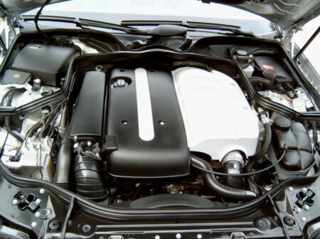 Service manual Mercedes-Benz OM646 Engine
9,99 $
ADD TO CART
Service manual Mercedes-Benz OM646 Engine
9,99 $
ADD TO CART -
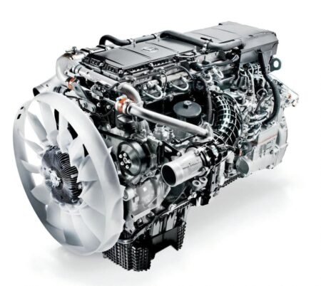 Service manual Mercedes-Benz OM473.9 Engine | Up to 2020 incl.
14,99 $
ADD TO CART
Service manual Mercedes-Benz OM473.9 Engine | Up to 2020 incl.
14,99 $
ADD TO CART -
 Service manual Mercedes-Benz W166 Models | Up to 2020 incl.
14,99 $
ADD TO CART
Service manual Mercedes-Benz W166 Models | Up to 2020 incl.
14,99 $
ADD TO CART -
 Service manual Mercedes-Benz M139 Engine | Up to 2020 incl.
14,99 $
ADD TO CART
Service manual Mercedes-Benz M139 Engine | Up to 2020 incl.
14,99 $
ADD TO CART -
 Service manual Mercedes 722.9, 722.6, 724.2 Automatic Transmission | 2015-2018
6,99 $
ADD TO CART
Service manual Mercedes 722.9, 722.6, 724.2 Automatic Transmission | 2015-2018
6,99 $
ADD TO CART -
 Service manual Mercedes-Benz OM471 Engine | Up to 2020 incl.
14,99 $
ADD TO CART
Service manual Mercedes-Benz OM471 Engine | Up to 2020 incl.
14,99 $
ADD TO CART
There are no reviews yet.